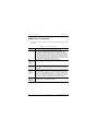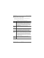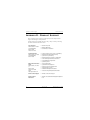
1
USER MANUAL
HiGain
DOUBLER
HDU-409
L
STATUS
HDU-409 Lists 1, 2, and 3 Doubler
Product Catalog: HDU-409-L1,
HDU-409-L2, HDU-409-L3
CLEI: T1R6AE0C, T1R6AEDC,
T1R6X50E
H0077-A
LTPH-UM-1234-01
Revision History of This Manual
To order copies of this manual, use document catalog number
LTPH-UM-1234-01.
Issue
Release Date
Revisions Made
01
April 29, 1998
Initial release of 150-409-100-01.
02
June 24, 1998
Modified front panel and cover. Changed deployment
rules. (150-409-100-02)
03
July 14, 1998
Corrected CLEI Code. (150-409-100-03)
04
December 18, 1998
Corrected CLEI Code; new LED indication for margins.
(150-409-100-04)
05
December 13, 1999
Added PG-Flex Fault applications and expanded the
thermal deployment rules. (150-409-100-05)
01
April 30, 2003
Rebranded PairGain document 150-409-100-05 to new
catalog number and updated to include List 3.
Copyright
April 30, 2003
© 2003 ADC DSL Systems, Inc. All rights reserved.
Trademark Information
ADC is a registered trademark of ADC Telecommunications, Inc. HiGain and
PG-Flex are registered trademarks of ADC DSL Systems, Inc. No right, license, or
interest to such trademarks is granted hereunder, and you agree that no such right,
license, or interest shall be asserted by you with respect to such trademark.
Other product names mentioned in this document are used for identification purposes
only and may be trademarks or registered trademarks of their respective companies.
Disclaimer of Liability
Information contained in this document is company private to ADC DSL Systems, Inc.,
and shall not be modified, used, copied, reproduced or disclosed in whole or in part
without the written consent of ADC.
Contents herein are current as of the date of publication. ADC reserves the right to
change the contents without prior notice. In no event shall ADC be liable for any
damages resulting from loss of data, loss of use, or loss of profits, and ADC further
disclaims any and all liability for indirect, incidental, special, consequential or other
similar damages. This disclaimer of liability applies to all products, publications and
services during and after the warranty period.
ii
April 30, 2003
HDU-409 Lists 1, 2, and 3
LTPH-UM-1234-01
Using This Manual
USING THIS MANUAL
The following conventions are used in this manual:
•
Monospace type indicates screen text.
•
Keys you press are indicated by small icons such as Y or ENTER . Key
combinations to be pressed simultaneously are indicated with a plus sign
as follows: CTRL + ESC .
•
Items you select are in bold.
The following types of messages, identified by icons, may be included in text:
Notes provide information about special circumstances.
General cautions indicate the possibility of personal injury,
product failure, or equipment damage if instructions are
ignored or not completely followed.
An Electrostatic Discharge (ESD) caution indicates that a
device or assembly is susceptible to damage from electrostatic
discharge.
An electrical shock caution indicates the presence of a
dangerous level of electrical power and the potential for
serious personal injury or equipment damage.
A laser caution indicates the potential for permanent eye
damage or blindness due to direct exposure to laser beams.
For a list of abbreviations used in this document, refer to “Appendix E Glossary” on page 34.
HDU-409 Lists 1, 2, and 3
April 30, 2003
iii
Unpack and Inspect Your Shipment
LTPH-UM-1234-01
UNPACK AND INSPECT YOUR SHIPMENT
Upon receipt of the equipment:
iv
•
Unpack each container and inspect the contents for signs of damage. If
the equipment has been damaged in transit, immediately report the extent
of damage to the transportation company and to ADC DSL Systems, Inc.
Order replacement equipment, if necessary.
•
Check the packing list to ensure complete and accurate shipment of each
listed item. If the shipment is short or irregular, contact ADC DSL
Systems, Inc. as described in “Appendix D - Product Support” on
page 32. If you must store the equipment for a prolonged period, store the
equipment in its original container.
April 30, 2003
HDU-409 Lists 1, 2, and 3
LTPH-UM-1234-01
Table of Contents
TABLE OF CONTENTS
Overview _______________________________________________ 1
Features ________________________________________________ 2
Product Description ______________________________________ 3
Applications ____________________________________________ 6
PG-Flex Deployment _____________________________________ 7
Generic Information______________________________________ 9
Doubler Enclosure Capacities with Full Solar Load................ 9
Alternative Doubler Enclosure Capacities............................. 16
Mixing HiGain Doublers ....................................................... 18
Micro Doubler Capacity Deployment Rules.......................... 18
Installation ____________________________________________ 20
Loopback Operation in HiGain Systems ____________________ 22
Appendix A - Functional Description_______________________ 25
Appendix B - Specifications_______________________________ 27
Appendix C - Ground Faults______________________________ 29
Ground Fault Detection.......................................................... 29
HiGain Fault Isolation............................................................ 30
PG-Flex Fault Isolation.......................................................... 31
Appendix D - Product Support ____________________________ 32
Appendix E - Glossary ___________________________________ 34
Certification and Warranty__________________Inside Back Cover
HDU-409 Lists 1, 2, and 3
April 30, 2003
v
List of Figures
LTPH-UM-1234-01
LIST OF FIGURES
1. HDU-409 Front Panel ...........................................................................3
2. Typical HDU Installation with PG-Flex ...............................................7
3. Two Doubler HDU Installation with PG-Flex ......................................8
4. AT&T 819 Enclosure, Slot Locations 1 through 14 ...........................17
5. Installing the HDU-409 in an Enclosure .............................................20
6. HiGain Loopbacks...............................................................................24
7. Doubler Block Diagram ......................................................................25
LIST OF TABLES
1. Front Panel Components and Labels ......................................................4
2. Front Panel Status Indicator LED...........................................................5
3. HDU-409 Circuit Ranges........................................................................6
4. HDU-409 Indoor Enclosure Capacities ................................................11
5. Capacities with Full Solar Load, 239 T1 Repeaters .............................12
6. Capacities with Full Solar Load, LD-1 Repeaters ................................15
7. SPLB Generic Command Set ...............................................................23
8. HDSL Signal Cable Loss......................................................................26
9. Fault Isolation Guide ............................................................................30
10. Fault Isolation Guide for PG-Flex ........................................................31
vi
April 30, 2003
HDU-409 Lists 1, 2, and 3
LTPH-UM-1234-01
Overview
OVERVIEW
The ADC® HiGain® HDU-409 Lists 1, 2, and 3 are low-power doubler units
that extend the range of a HiGain repeaterless T1 transmission system. The
doubler units are installed between any doubler-compatible HiGain Line Unit
(HLU) and a HiGain Doubler Unit (HDU) or HiGain Remote Unit (HRU).
Each doubler allows 1.544 Mbps transmission over an additional Carrier
Serving Area (CSA) range.
Each CSA with one doubler encompasses approximately 24,000 feet (7.3 km)
using 24 American Wire Gauge (AWG) or 18,000 feet (5.5 km) using
26 AWG loops. Two doublers can triple the CSA range up to 36,000 feet
(11 km) using 24 AWG or up to 27,000 feet (8.2 km) using 26 AWG loops.
Three doublers extend the 24 AWG range up to 48,000 feet (14.6 km) and
four doublers (with a locally-powered HRU) extend the range up to
60,000 feet (18.3 km). The HDU-409 Lists 1, 2, and 3 are identical except
that:
•
The List 1 is only compatible with the HiGain product line.
•
Lists 2 and 3 are compatible with HiGain and PG-Flex® product lines.
Refer to “PG-Flex Deployment” on page 7 for more information regarding
the PG-Flex doubler applications.
HDU-409 Lists 1, 2, and 3
April 30, 2003
1
Features
LTPH-UM-1234-01
FEATURES
2
•
The unit occupies one standard 239 T1 mechanics slot.
•
Powered by any doubler-compatible HiGain or PG-Flex (List 2 or List 3
only) Central Office (CO) line unit.
•
Front-panel status display Light Emitting Diode (LED).
•
Lightning and power-cross protection on both sides of the High-bit-rate
Digital Subscriber Line (HDSL) interface.
•
Extremely low power dissipation.
•
Extremely low latency.
•
Can be used in four-span line-powered circuits (three doublers and one
remote) or five-span locally-powered circuits (four doublers and one
remote).
•
Compatible with PG-Flex List 3x line units in configurations with up to
three spans.
•
Complies with the applicable requirements of Network Equipment
Building System (NEBS) Generic Equipment requirements of GR 1089
CORE and GR 63 CORE compliance.
•
Minimal wander and jitter.
April 30, 2003
HDU-409 Lists 1, 2, and 3
LTPH-UM-1234-01
Product Description
PRODUCT DESCRIPTION
The open-framed cover reduces thermal stress and improves reliability,
allowing air to freely circulate over all components. The open cover also
permits the doubler to be easily distinguished from the 239 T1 repeater.
Figure 1 on page 3 shows the front panel of the HDU-409 and
Table 1 on page 4 describes the doubler unit components and labels.
Configuration
number label
(located on top)
HiGain
DOUBLER
HDU-409
List number
L
Status LED
STATUS
CLEI/ECI bar
code label
Extraction
handle
H0078-A
Figure 1.
HDU-409 Lists 1, 2, and 3
HDU-409 Front Panel
April 30, 2003
3
Product Description
LTPH-UM-1234-01
Table 1.
Front Panel Components and Labels
Name
Function
Status LED
Indicates operational status of doubler
(see Table 2 on page 5).
Contains human-readable Common Language Equipment
Identifier (CLEI) code number and Equipment Catalog Item
(ECI) bar code number.
For some products the configuration number may contain
either a five- or six-digit warranty configuration number or a
stand-alone two- or three-digit configuration number as
follows:
Digit 1 - Last digit of shipment year.
CLEI/ECI Bar
Code Label
Configuration
number
Digits 2 and 3 - Shipment month.
Digits 4, 5, and 6 - Configuration number.
The configuration number identifies the version of the product.
New configuration numbers usually accompany changes in
the last two characters of the CLEI code.
The configuration number can also be found on a small bar
label that also contains the Julian date code. The configuration
number appears as either a stand-alone CFG xx number or as
a 15-character number comprised of the part number and a
3-character extension. For example, the number
150-2404-15-x03 is comprised of the part number and an x03
configuration number. This gummed label may be attached to
the PC board or to the front panel.
The front panel of the HDU-409 contains a tri-color LED. The LED color and
activity provides information on system functionality. Table 4 provides a list
of all alarm indications in priority order.
4
April 30, 2003
HDU-409 Lists 1, 2, and 3
LTPH-UM-1234-01
Product Description
Table 2.
Front Panel Status Indicator LED
LED
Description
Flashing Red about
once per second
Indicates an HDSL Cyclic Redundancy Check (CRC) error has
occurred between the HDU-409 and the upstream module.
Flashing Red rapidly
Indicates an HDSL CRC error has occurred between the
HDU-409 and the downstream module.
Flashing Yellow about
once per second
Indicates a Network Doubler Unit (NDU) loopback is in effect in
the HDU-409 towards the network. This tests the integrity of the
upstream span.
Flashing Yellow
rapidly
Indicates a Customer Doubler Unit (CDU) loopback is in effect in
the HDU-409 towards the customer. This tests the integrity of the
downstream span.
Flashing Green about
once per second
Indicates synchronization is being attempted between the
HDU-409 and the upstream (network) module.
Flashing Green rapidly Indicates synchronization is being attempted between the
HDU-409 and the downstream (customer) module.
Steady Yellow
Indicates the HDSL margin is less than the margin threshold
provisioned for the circuit.
Steady Green
Indicates HDSL frame synchronization has been achieved
between the HDU-409 and both the upstream and downstream
modules.
HDU-409 Lists 1, 2, and 3
April 30, 2003
5
Applications
LTPH-UM-1234-01
APPLICATIONS
HiGain doublers operate with any number of other T1, Plain Old Telephone
System (POTS), Digital Data Service (DDS), or other HiGain systems
sharing the same cable binder group.
The HDU-409 can be used in two- to five-span circuits, depending on the
models of the HLU and HRU being used with the doubler units and the power
option chosen for the HRU. The number of doublers is equal to one less than
the number of spans as shown in Figure 6 on page 24.
Table 3 lists the maximum number of HDU-409 doubler units that can be
deployed according to which HLU and HRUs are used.
Each span can take up to 30 seconds to acquire HDSL
synchronization. The total time to acquire end-to-end
synchronization increases with the number of spans.
Table 3. HDU-409 Circuit Ranges
Maximum Number of HDU-409 Doublers Per Circuit
HLU Model
HLU-388 List 2x,
HLU-319 List 2x,
HLU-231 List 3D,
HLU-231 List 6D,
HLU-232 List 1D
HLU-231 List 7x,
HLU-431 List 1D
HLU-231 List 8D,
HLU-319 List 5D,
HLU-388 List 5D
HLU-231 List 8/List 8E,
HLU-319 List 5/List 5E,
HLU-388 List 5/List 5E
(a)
Line-Powered Remote
Locally-Powered Remote
I-CPE ON
I-CPE ON
I-CPE OFF
1
2
2
3
(b)
I-CPE OFF
2
2
2
4
(c)
(a) HRU-411 applications with Current-Customer Premises Equipment (I-CPE) ON are
limited to single HDU-409 doubler circuits. The HRU-412 is limited to applications with
one and two doublers only.
(b) Requires HRU-402 or HRU-411.
(c) Requires HRU-402 List 1 or List 3.
6
April 30, 2003
HDU-409 Lists 1, 2, and 3
LTPH-UM-1234-01
PG-Flex Deployment
PG-FLEX DEPLOYMENT
Figure 2 shows a typical HDU-409 List 2 or List 3 installation for the
PG-Flex subscriber carrier system. For each doubler installed between the
PG-Flex Central Office Terminal (COT) and Remote Terminal (RT), two
auxiliary power pairs are required between the COT and RT. A maximum of
two doublers may be installed in a PG-Flex system.
Auxiliary Power Pairs
Span 1
PG-Flex
COT
HDU-409
Doubler
Span 2
HDSL
HDSL
9,000' 26 AWG
12,000' 24 AWG
9,000' 26 AWG
12,000' 24 AWG
PG-Flex
RT
9,000' 26 AWG or 12,000' 24 AWG (without Doubler)
H0079-A
Figure 2.
HDU-409 Lists 1, 2, and 3
Typical HDU Installation with PG-Flex
April 30, 2003
7
PG-Flex Deployment
LTPH-UM-1234-01
With two doublers, four sets of auxiliary power pairs must be installed
between COT and the RT. These auxiliary power pairs must be the same wire
gauge (or larger) as the pairs used for HDSL and power.
Auxiliary Power Pairs
PG-Flex
COT
Span 1
HDSL
Doubler 1
HDU-409-L2
HDU-409-L3
Span 2
HDSL
Doubler 2
HDU-409 L2
HDU-409-L3
Span 3
HDSL
PG-Flex
RT
H0075-A
Figure 3. Two Doubler HDU Installation with PG-Flex
PG-Flex systems do not support doubler loopbacks.
The PG-Flex system can operate with a number of other systems, sharing the
same cable binder group, such as:
•
T1 (1.544 Mbps capability)
•
POTS
•
DDS
•
Other PG-Flex systems
With doublers, PG-Flex CO line units produce ±125V to ±130V on the HDSL
and auxiliary power pairs. At least ±75V is required at the RT for ringer
voltage and POTS loop current to meet specification.
Refer to the PG-Flex COT shelf, RT enclosure, and line unit practices for
additional information on PG-Flex powering and auxiliary power pair
requirements (see “Documentation” on page iii).
8
April 30, 2003
HDU-409 Lists 1, 2, and 3
LTPH-UM-1234-01
Generic Information
GENERIC INFORMATION
This section provides generic information for both the HiGain and PG-Flex
applications.
DOUBLER ENCLOSURE CAPACITIES WITH FULL
SOLAR LOAD
The physical location of the doublers is driven by the following three
deployment rules:
1
Place the enclosures at the electrical limits (35 dB) of each span. This
places the first doubler at the 35 dB location and the second at 70 dB and
so on. This allows the maximum circuit range to be realized.
Caution must be observed when pushing doubler spans to
their 35 dB maximum range. Refer to ADC’s Technical
Advisory #TA-015 on HiGain operating ranges and general
deployment guidelines.
2
If Rule 1 is not applicable, try to make all spans the same electrical length
(same 196 kHz loss). This minimizes the maximum span loss and assures
maximum operating margin, resulting in optimal transmission
performance on the HDSL cable pairs. If specific application constraints
preclude using rule 2 or, if two different circuit layout choices have the
same maximum span loss, then use Rule 3.
HDU-409 Lists 1, 2, and 3
April 30, 2003
9
Generic Information
3
LTPH-UM-1234-01
This rule minimizes power consumption and dissipation from the HLU
providing doubler power. It requires the spans closer to the HLU to be as
short as possible and the spans farther from the HLU to be as long as
possible. This choice minimizes the I2R loss in the cable pairs and
reduces the thermal stress on the HLU.
Only those HRUs that have a local powering option can be
used in local HRU-powered applications.
The HDU-409 can be housed in a variety of outdoor enclosures manufactured
by ADC and a variety of other vendors. The number of doublers used in any
of the enclosures depends on the maximum outside ambient temperature. The
doubler capacities for several of these standard enclosures are listed in
Table 4, Table 5, and Table 6 starting on page 11. The capacities listed in
Table 5 and Table 6 are based on a maximum outside temperature of +115°F
(+46.1°C). Consult ADC for the latest deployment rules when using the
enclosures at ambient temperatures above 115 °F or when using enclosures
not listed.
These requirements comply with Bellcore standards, which
require HDSL equipment placed in outdoor cabinets to
operate in an outside ambient temperature of -40°F (-40°C)
with no solar load and +115°F (+46.1°C) with a maximum solar
load and maximum power dissipation.
Full solar load is equal to maximum sunlight exposure as
defined in Bellcore’s Technical Advisory TR-TSY-000057.
The capacities listed for the indoor enclosures in Table 4 on page 11 assume
no solar load. The capacities listed for the outdoor enclosures in Table 5 and
Table 6 on page 15 assume a full solar load as described above. The
“Recommended Slot Assignment for Maximum Capacity” column assigns
slots according to the following thermal stress reduction rules:
10
April 30, 2003
HDU-409 Lists 1, 2, and 3
LTPH-UM-1234-01
1
Generic Information
Always leave at least one empty slot between adjacent doublers. The
adjacency rule only applies to the left and right sides of the doubler. The
top of one unit can be adjacent to the bottom of another, but should be
avoided.
Rule 1 does not apply to the HRE-819, the Keptel RF 819, and
all enclosures listed in Table 5 on page 12 with Universal Card
Cage enclosures. These products have the required slot
separations built into their design.
2
Allow as much room as possible between doublers on all four sides.
Table 4.
HDU-409 Indoor Enclosure Capacities
Vendor
Description
Model No.
HDU-409
Doubler
Capacity
239 T1
Repeater
Capacity
CHARLES
Indoor wall mount
CiAC2300
7
7
CiAC2002
2
2
4400-09
18
18
SPC
Indoor rack/wall mount
HDU-409 Lists 1, 2, and 3
April 30, 2003
11
Generic Information
Table 5.
LTPH-UM-1234-01
Capacities with Full Solar Load, 239 T1 Repeaters
Vendor
Description
Model No.
AT&T
Outdoor dual
chamber
pole/wall
mount
819
14
25
1, 3, 5, 7, 8, 10,
12, 14, 15, 17,
19, 21, 23, 25
(See Figure 4)
Outdoor 841
cabinet
27A, B, C or D
shelf
13 per
shelf/
52 total
25 per
shelf/
100 total
All odd slots
Outdoor
cabinet
809
6
12
(a)
Outdoor
canister,
pole/wall
mount
621204
6
12
(a)
621205
11
25
All even or odd
slots from 1 to
12, plus 14,17,
19, 22 and 25
621206
19
50
All even or odd
slots from 1 to
12, plus 14,17,
19, 22, 25, 28,
31, 34, 35, 38,
41, 44, 48
CIAC4306
3
6
(a)
CIAC3300
2
3
1, 3
CIAC5312
5
12
(a)
CIAC5325
7
25
1, 3, 5, 7, 9, 11,
13, 15, 17, 22
24
CIAC5350
9
50
All odd slots
from 1-33
CIAC6321
2
2
All slots
3011
3
6
(a)
3021
3
5
1, 3, 5
ALCATEL
(Available
from
Charles
Ind.)
CHARLES
SIERRA
SUNRISE
12
Outdoor
canister,
pole/wall
mount
Outdoor
canister,
pole/wall
mount
April 30, 2003
239 T1
Repeater
Capacity
Recommended
Slot
Assignment for
Maximum
Capacity
HDU-409
Doubler
Capacity
HDU-409 Lists 1, 2, and 3
LTPH-UM-1234-01
Table 5.
Generic Information
Capacities with Full Solar Load, 239 T1 Repeaters (Continued)
Vendor
Description
Model No.
ABACON
Outdoor dual
chamber
pole/wall
mount
HDSL 16
14
16
All slots but
1 and 16
SPC
Outdoor
canister,
pole/wall
mount
7130-08FP
4
8
1, 3, 6, 8 or 2, 4,
5, 7
7130-12FP
6
12
(a)
7130-25FP
10
25
All odd slots
from 1-19
7130-0656P-TA
7130-0656PTB2
6
6
All slots
7130-V856PTQA
7130-V856PTQB
7130-08P-UNIVHORZ-TQB2
8
8
7030-12P-UNIVVERT-TQA
7030-12P-UNIVHORZ-TQA
7030-12P-UNIVVERT-TQB2
7030-12P-UNIVHORZ-TQB2
12
12
7130-1656-QA
12
16
Outdoor
canister,
pole/wall
mount with
universal
card cage
HDU-409 Lists 1, 2, and 3
April 30, 2003
239 T1
Repeater
Capacity
Recommended
Slot
Assignment for
Maximum
Capacity
HDU-409
Doubler
Capacity
Slots 1-12
13
Generic Information
Table 5.
LTPH-UM-1234-01
Capacities with Full Solar Load, 239 T1 Repeaters (Continued)
HDU-409
Doubler
Capacity
239 T1
Repeater
Capacity
Recommended
Slot
Assignment for
Maximum
Capacity
Vendor
Description
Model No.
SPC
Dual dome
outdoor
canister wall
mount with
universal
card cage
7030-24P-UNIVHORZ-TQA
7030-24P-UNIVHORZ-TQB2
24
24
All slots
7030-32P-UNIVHORZ-TQA
24
32
Any 12 in each
chamber
HRE-458
10
10
All slots
HRE-504
4
4
HRE-506
6
6
HRE-500
1
1
ADC
14
Outdoor
canister,
pole/wall
mount with
universal
card cage
HRE-602
2
2
Outdoor dual
chamber,
pole/wall
mount
HRE-819
12
12
Dual dome
outdoor
canister wall
mount with
universal
card cage
HRE-524
24
24
April 30, 2003
HDU-409 Lists 1, 2, and 3
LTPH-UM-1234-01
Table 5.
Generic Information
Capacities with Full Solar Load, 239 T1 Repeaters (Continued)
239 T1
Repeater
Capacity
Recommended
Slot
Assignment for
Maximum
Capacity
Vendor
Description
Model No.
HDU-409
Doubler
Capacity
KEPTEL
Outdoor
single
chamber
RF 809
6
12
(a)
Outdoor dual
chamber
RF 819
12
12
All slots
Outdoor
single
chamber
RF 820
8
8
(a) All even or all odd-numbered slots.
Table 6.
Capacities with Full Solar Load, LD-1 Repeaters
HDU-409
Doubler
Capacity
LD-1
Repeater
Capacity
Vendor
Description
Model No.
NORTEL
LD1
Outdoor
canister,
pole/wall
mount
QCD14 (A & B) 4
6
QCD15 (A & B) 6
QCD10 A
12
QCD7 A
10
QCD16 (A & B)
QCD8 (A & B)
25
QCD9 (A & B) 20
QCD17 (A & B)
50
Recommended
Slot Assignment
for maximum
Capacity
2 per row,
non-adjacent,
staggered
(non-overlapping)
Thermal constraints must be observed to ensure reliable
service for worst-case conditions.
HDU-409 Lists 1, 2, and 3
April 30, 2003
15
Generic Information
LTPH-UM-1234-01
ALTERNATIVE DOUBLER ENCLOSURE
CAPACITIES
Reduce the doubler capacity by one for every two doublers that do not have
an empty slot between them. If the application allows seven doublers, but two
are directly adjacent to each other, then the total capacity must be reduced to
six.
Standard T1 or LD1 repeaters can be installed in the same enclosure with
doubler units. If this method is used, the maximum number of doublers that
can occupy the same case with the standard repeaters must be reduced by one
for every four T1 or LD1 repeaters (or fractions thereof) installed.
Rule one on page 11, in the section titled, “Doubler Enclosure
Capacities with Full Solar Load” on page 9, does not apply if
the adjacent slot is occupied by a T1 or LD1 repeater;
however, slots adjacent to doublers should be left vacant if
possible.
16
April 30, 2003
HDU-409 Lists 1, 2, and 3
LTPH-UM-1234-01
Generic Information
The AT&T 819 enclosure has two, individual isolated chambers as shown in
Figure 4. Slots 1 through 14 are in one chamber. The other chamber contains
slots 15 through 25, along with the Pressure (PRES), Filter (FIL), Capacitor
(CAP), and COIL slots.
.
Top
8
D5
9
10
D6
11
12
D7
13
14
D8
20
21
D12
22
23
D13
24
1
D1
2
3
D2
4
5
D3
6
7
D4
15
D9
16
17
D10
18
19
D11
Chamber 1
25
D14
P
R
E
S
F
I
L
Chamber 2
Bottom
Figure 4.
C
O
I
L
C
A
P
H0080-A
AT&T 819 Enclosure, Slot Locations 1 through 14
The AT&T 819 can house up to 14 HDU-409 doublers in the slots designated
as D1 through D14 as shown in Figure 4.
Because the length of the HDU-409 extends beyond the depth
that older AT&T 819 T1 repeater apparatus covers can
accommodate, the cover must be replaced by a deeper cover.
HDU-409 Lists 1, 2, and 3
April 30, 2003
17
Generic Information
LTPH-UM-1234-01
MIXING HIGAIN DOUBLERS
The HiGain HDU-439 mini doubler can also be installed along with the
HDU-409 micro doubler in the same enclosure. Assign a thermal weight of
1.5 HDU-409 for every HDU-439 and round down to the nearest whole
number. This results in one of the following thermal relationships:
a) 1.5 (HDU-409) = 1 (HDU-439)
b) 1 (HDU-409) = 2/3 (HDU-439)
For example, if an AT&T 819 case has only 10 HDU-409 doublers leaving
room for four more HDU-409 doublers, the number of HDU-439 doublers
that can be allotted to these 4 slots is determined by using (b) as follows:
4 (HDU-409) = (4) (2/3) (HDU-439)
4 (HDU-409) = 2.66 (HDU-439) = 2 (HDU-439)
Similarly the number of HDU-439 doublers that can be allotted to 6 empty
HDU-409 slots is:
6 (HDU-409) = (6) (2/3) (HDU-439) = 3 (HDU-439)
When assigning slot locations, make sure there is an empty
slot between any two adjacent doublers (HDU-409 and
HDU-439).
MICRO DOUBLER CAPACITY DEPLOYMENT
RULES
The deployment rules for micro doubler capacity are summarized below:
18
1
Use Table 4 on page 11 for indoor enclosures.
2
Use Table 5 and Table 6 on page 15 for outdoor enclosures with full
solar load for ambient temperatures up to 115°F maximum.
3
The capacities shown in Table 5 can be increased to all odd or even slots
(where applicable) for non-solar load (shaded or manhole applications).
The non-adjacency constraint still applies for these increased capacity
applications. The capacity of the ABACON HDSL 16 enclosure can be
increased to 16 for non-solar load applications.
April 30, 2003
HDU-409 Lists 1, 2, and 3
LTPH-UM-1234-01
Generic Information
4
For non-solar applications in an environment up to 95°F maximum, the
capacity for an SPC, 32-slot 7030-32P enclosure can be increased to all
32 slots.
5
Decrease capacities in Table 5 and Table 6 on page 15 by five percent
(round up to the nearest whole number) for every 5°F (2.8°C) increase,
or fraction thereof, in ambient temperatures above 115°F (46°C). Always
assign the empty slots to the highest (uppermost) positions.
6
Increase the capacities by five percent (round down to the nearest whole
number) for every full +5°F (2.8°C) reduction in ambient temperature,
below 115°F (46°C). The non-adjancency constraint still applies for
these increased capacity applications.
7
Decrease any outdoor capacity by one for every four T1 or LD1
repeaters, or fraction thereof, that are installed with the doublers.
8
For all outdoor applications, decrease the capacity by one for every two
adjacent doublers that are not separated by at least one empty slot.
HDU-409 Lists 1, 2, and 3
April 30, 2003
19
Installation
LTPH-UM-1234-01
INSTALLATION
To install the HDU-409 in an enclosure, perform the following steps and refer
to the enclosure installation manual for information about cabling, proper
connections, grounding, and line and local power (see “Documentation” on
page iii).
This product incorporates static sensitive components.
Proper electrostatic discharge procedures must be followed.
Enclosure
H0081-A
STA
TU
S
HDU
Figure 5. Installing the HDU-409 in an Enclosure
20
April 30, 2003
HDU-409 Lists 1, 2, and 3
LTPH-UM-1234-01
Installation
1
To install the doubler unit, slide the doubler unit into the card guides for
the desired slot (see Figure 5 on page 20).
2
Next, push the unit into the enclosure until it is seated in the card-edge
connector. The unit snaps into place, indicating that it is properly seated.
Once the HDU-409 is installed in the enclosure, the front panel Status LED
flashes green to indicate power is applied from an upstream line unit. When
the loops on both sides of the HDU synchronize, the LED is steady green.
Refer to Table 2 on page 5 for more details on LED operations.
HDU-409 Lists 1, 2, and 3
April 30, 2003
21
Loopback Operation in HiGain Systems
LTPH-UM-1234-01
LOOPBACK OPERATION IN HIGAIN
SYSTEMS
Doubler loopbacks work only with HiGain systems. PG-Flex
does not support doubler loopbacks.
When equipped with the HDU-409 a HiGain system can execute the types of
loopbacks listed in Table 7.
The loopbacks can be initiated from any of the following:
22
•
The HLU craft port
•
The HLU front-panel buttons
•
A family of Special Loopback (SPLB) in-band commands initiated at the
T1 input port at either the HLU or HRU
•
The HRU craft port, if remote provisioning is enabled from the HLU
April 30, 2003
HDU-409 Lists 1, 2, and 3
LTPH-UM-1234-01
Loopback Operation in HiGain Systems
The SPLB generic command set for four-doubler loopbacks is listed in
Table 7. The commands are specific combinations of either 6 or 7 bits that
continuously repeat. All NDUx loopbacks are towards the network. All
CDUx loopbacks are towards the customer. Figure 6 on page 24 is a diagram
of the various HiGain loopbacks.
Table 7.
SPLB Generic Command Set
Command Set
Loopback
NDU1
1 1 0 0 0 0 (2-in-6)
NDU2
1 1 1 0 0 0 (3-in-6)
NDU3
1010001
NDU4
1010010
CDU1
1 1 1 1 0 0 (4-in-6)
CDU2
1 1 1 1 1 0 (5-in-6)
CDU3
1011001
CDU4
1011010
HDU-409 Lists 1, 2, and 3
April 30, 2003
23
Loopback Operation in HiGain Systems
LTPH-UM-1234-01
Loopbacks Toward Network
TLOS
HRU-412
LOGIC
HRU-412
HDSL SPAN
HLU
All ones
HRU
SMJK*
HDSL SPAN
HLU
11000
HRU-412
2-in-5
HRU-412
All ones
HRU
NREM*
NREM
HDSL SPAN
HLU
1110000
HRU-412
3 in 7
3-in-7
HRU-412
All ones
DSX-1
SPAN
HLU4
1NDU4
UDC
1NDU1
UDC
1NDU2
UDC
1NDU3
UDC
2-in-6
3-in-6
6 ni 4
6 ni 4
6 ni 4
SPAN 2 111000 SPAN 3 1010001 SPAN 4 1010010 SPAN 5
SPAN 1 110000
001111
001111
001111
90HDU
4-UDH
90HDU
4-UDH
90HDU
4-UDH
90HDU
4-UDH
NLOC
1111000
HLU
CLOC
HRU-412
Loopbacks Toward Customer
CREM
6-in-7
HLU
All ones
HRU-412
5 IN 7 All ones
HRU
HDSL SPAN
4-in-7
HLU
All ones
HRU
CI-Customer Interface
HRU-412
HRU
HDSL SPAN
1111110
HRU
HLU
CLOC
All ones
HDSL SPAN
HLU
5-in-7
5 IN 7
1111100 HRU-412
HRU-412
HRU
All ones
HLU
SPAN 1
CDU1
4-in-6
SPAN 2
111100
HDU
CDU2
CDU3
CDU4
5-in-6
SPAN 3 1011001 SPAN 4 1011010 SPAN 5
111110
HDU
HDU
HDU
HRU
* Set the SAIS option to ENA to send AIS (indicated by an all ones pattern) to the CI during SmartJack loopback, NREM, and TLOS.
Use the 3-in-5 code to loop down.
H0082-A
Figure 6.
HiGain Loopbacks
For more information about other doubler loopback commands, see the
appropriate HLU user documentation.
24
April 30, 2003
HDU-409 Lists 1, 2, and 3
LTPH-UM-1234-01
Appendix A - Functional Description
APPENDIX A - FUNCTIONAL
DESCRIPTION
HiGain uses the ADC Two-Binary, One-Quaternary (2B1Q) HDSL
transceiver system to establish two full-duplex 784 kbps data channels
between the HLU, HDU, and HRU units. Each HDU-409 increases the
maximum range by approximately 12,000 feet (3.7 km) using 24 AWG or
9,000 feet (2.75 km) using 26 AWG per doubler. See Table 2 on page 3 for
deployment rules.
A block diagram of the HDU-409 with pinouts is shown in Figure 7 on
page 25. The doubler unit power supply uses the HDSL simplified line
voltage to produce +5 Vdc and +3 Vdc required by the HDU-409 electronics.
The power feed is passed on to the HDSL output pair to power a second
doubler or a remote unit.
The typical power dissipation of the doubler unit is 3W.
Tip
6
HDSL 1 IN
Ring
5
CO
4 Tip
Loop 1
3 Ring
Power
Supply
80 to 200 V
and
+
GFD
HDSL 1
OUT
475 K
+5 V HDSL
IN
+3 V XCVRS
HDSL
OUT
XCVRS
Field
Output
Span
Voltage Status
Control
10
1
Frame
Ground
Microprocessor
Tip
9
HDSL 2 IN
Ring
8
Loop 2
12 Tip
HDSL 2 OUT
11 Ring
H0083-A
Figure 7.
HDU-409 Lists 1, 2, and 3
Doubler Block Diagram
April 30, 2003
25
Appendix A - Functional Description
LTPH-UM-1234-01
Table 8 on page 26 provides a guide for the loss that occurs when using
various cable gauges at 196 kHz and 135Ω. It applies to the HDSL cable pairs
between the COT and the HDU, and between the HDU and the RT.
To achieve optimum performance, make the electrical length (196 kHz loss)
of all HDU spans as close to equal as possible. This results in the highest
operating loop margins. If it is not possible to make all spans equal, choose
span lengths that reduce the total power consumption of the CPT that powers
the HDU. Do this by minimizing the length of Span 1 and Span 2. Use Table 8
on page 26 when you calculate the electrical length of each span.
The HDU-409 has a range of up to 35 dB loss at 196 kHz on each of the four
HDSL loops. A list of HDSL signal cable losses for various cable gauges at
196 kHz and 135Ω is provided in Table 8. The table is applicable to HDSL
cable pairs running between the HLU and the HDU-409 and between the
HDU-409 and another HDU or HRU.
Table 8.
HDSL Signal Cable Loss
Cable Gauge
Ω per kFt
(0.3048 km)
Loss @ 196 kHz
(dB per kFt) (a)
26 AWG/0.4 mm
83.3
3.880
24 AWG/0.51 mm
51.9
2.841
22 AWG/0.61 mm
32.4
2.177
19 AWG/0.91 mm
16.1
1.535
(a) Add 3 dB for each bridged tap and 1 dB for each cable gauge change.
26
April 30, 2003
HDU-409 Lists 1, 2, and 3
LTPH-UM-1234-01
Appendix B - Specifications
APPENDIX B - SPECIFICATIONS
Appendix A lists the specifications for the HDU-409.
HDSL
Line Code
784 kbps, 2B1Q full duplex
Output
+13 dBm
Line Impedance
135Ω
Resistive Signature
Input/Output
5Ω (typical)
Start-up Time
(per span)
15 seconds (typical), 30 seconds (maximum)
Line Clock Rate
Power Dissipation
Maximum
Provisioning Loss
Wander and Jitter
Internal Stratum 4 clock
Latency
Mounting
Electrical Protection
80 µs (maximum either direction)
HDU-409 Lists 1, 2, and 3
3.0W (nominal)
35 dB @ 196 kHz, 135Ω
Nominal - The absence of an HDSL framer from the
HDU-409 reduces the Doubler Unit effect on a
circuit’s overall wander and jitter to second order
insignificance when compared to the wander and jitter
of other circuit modules.
Single 239 T1 Mechanics slot
Secondary surge and power cross protection on all
HDSL ports
April 30, 2003
27
Appendix B - Specifications
LTPH-UM-1234-01
Environmental
Operating
Temperature
-40°F (-40°C) to +149°F (+65°C)
Operating Humidity 5% to 95%
(non-condensing)
Operating
Temperature in
Outside Enclosures
Complies with Section 10.2.1.3 of
TA-NWT-001210
Operating Elevation 200 feet (61m) below sea level to 13,000 feet (4 km)
above sea level
Dimensions
HDU-409 (Single 239 T1 Mechanics)
Height
2.6 inch (6.6 cm)
Width
0.75 inch (1.9 cm)
Depth
6.5 inch (16.5 cm)
Weight
0.8 lbs (0.36 kg)
The HDU-409 Lists 1, 2, and 3 are compatible with the following ADC
outdoor enclosures:
28
•
HRE-500, single-slot unit
•
HRE-458, 10-slot unit
•
HRE-819, 12-slot unit
•
HRE-504, four-slot unit
•
HRE-506, six-slot unit
•
HRE-602, two-slot unit
•
HRE-524, 24-slot unit
April 30, 2003
HDU-409 Lists 1, 2, and 3
LTPH-UM-1234-01
Appendix C - Ground Faults
APPENDIX C - GROUND FAULTS
GROUND FAULT DETECTION
The HDU-409 has Ground Fault Detection (GFD) circuits as described in
R7-1, Section 7.2.1 of GR-1089 CORE, Issue 1, Revision 1, December, 1996.
When used with HiGain line units, ground faults occurring at any point along
any span are immediately detected. Ground fault conditions shut the HiGain
circuit down. The line unit periodically tries to apply power to the first span
to determine whether the fault condition is still present. As long as the
condition exists, the power cycling and ground fault protection continues. To
discontinue the ground fault protection, locate and repair the fault in the
cable.
Circuits containing both the HDU-409 and older doublers without a GFD
circuit also support this new ground fault detecting feature, provided the
doubler nearest the HLU is an HDU-409.
To operate properly, the ground fault circuit requires that the
doubler enclosure ground plane be securely connected to
earth ground. Failure to do so can cause false triggering of the
GFD circuit.
HDU-409 Lists 1, 2, and 3
April 30, 2003
29
Appendix C - Ground Faults
LTPH-UM-1234-01
HIGAIN FAULT ISOLATION
Solutions for common problems that may occur with the HDU-409 are listed
in Table 9.
Table 9.
Fault Isolation Guide
Problem
Solution
LED does
not light
1 Verify that the HLU is installed and operational in the CO.
2 Verify proper cabling between the doubler enclosure and the CO.
3 Measure 100 to 200 Vdc between pins 5 or 6 and 8 or 9. This voltage
peaks every 15 to 30 seconds as the HLU cycles between self test and
line power. If less than 100 Vdc is present, check the cabling or the HLU.
Only the line units mentioned in the “Applications” section can be used
to power doublers (see Table 3 on page 6). Other HLU models may not
provide reliable operation and should not be used.
LED
continues to
flash green
once a
second
Synchronization is being attempted with the upstream unit.
HDU-409
loses power
The HLU at the CO is not present. Measure the resistance of the HDSL input
loop. Resistance should be normal loop resistance plus the 25Ω signature
of the HLU.
HDSL line
power only
appears in
very short
bursts
A grounded pair is being detected by either the HLU or HDU-409 in Span 1.
This causes the unit’s GFD circuit to trigger which forces the HDSL line
voltage off immediately after it cycles on. Remove the HLU and HDU-409
and check for cable ground faults in Span 1. The doubler’s GFD circuit can
easily be checked by grounding any of the loop connectors to the doubler.
This forces the circuit down immediately. If the circuit stays up, either the
GFD circuit is defective or the HDU-409 is not properly grounded.
HDU-409
shuts off
after Span 1
comes up
A grounded pair is being detected by the HDU-409 in Span 2. Remove
HDU-409 and check for ground fault in Span 2.
30
April 30, 2003
HDU-409 Lists 1, 2, and 3
LTPH-UM-1234-01
Appendix C - Ground Faults
PG-FLEX FAULT ISOLATION
Solutions for common problems that may occur with the HDU-409 in
PG-Flex applications are listed in Table 10.
Table 10.
Fault Isolation Guide for PG-Flex
Problem
Solution
LED does
not light
1 Verify that the PG-Flex COLU is installed and operational in the CO.
2 Verify proper cabling between the doubler enclosure and the CO.
3 Measure 150 Vdc between pins 5 or 6 and/or 9 of the HDU. This voltage
peaks every two minutes during the HDSL startup cycle. If less than 100
Vdc is present, check the cabling between the doubler enclosure and
PG-Flex COT shelf. Refer to the COLU practice and verify the COLU is
operating properly.
LED
continues to
flash green
once a
second
Synchronization is being attempted with the upstream unit.
HDU-409
loses power
1 The COLU at the CO is not present or is not operating properly.
2 Check the cabling between the doubler housing and the PG-Flex COT
shelf. Measure the resistance of the HDSL input loop. Resistance should
be normal loop resistance plus the 25Ω signature of the COLU.
HDSL line
power only
appears in
very short
bursts
With PG-Flex the GFD is in the COT line unit. Tip or ring ground faults
between the COT and the doubler causes the power to turn on for a few
seconds every two minutes. With the HDU-409 doubler, a ground fault after
the doubler on Loop 2 has the same affect. On Loop 1, however, the DC
power does not shut off because of a ground fault. When there is a ground
fault on Loop 1, the doubler limits its output voltage to approximately -40V.
Pair 2 maintains the normal 130V. This is enough voltage to power the
doubler, but not the RT. Typically the HDSL Loop 1, after the doubler, will
drop the resync periodically. Note that if the pairs are reversed, the polarity
of the voltages are reversed.
Remove the line units and doublers and check for cable faults.
HDU-409
shuts off
after Span 1
comes up
A grounded pair is being detected by the HDU-409 in Span 2. Remove
HDU-409 and check for ground fault in Span 2.
HDU-409 Lists 1, 2, and 3
April 30, 2003
31
Appendix D - Product Support
LTPH-UM-1234-01
APPENDIX D - PRODUCT SUPPORT
ADC Customer Service Group provides expert pre-sales and post-sales
support and training for all its products.
Technical support is available 24 hours a day, 7 days a week by contacting
the ADC Technical Assistance Center.
Sales Assistance
800.366.3891 ext. 73000
(USA and Canada)
952.917.3000
Fax: 952.917.3237
• Quotation Proposals
Systems Integration
800.366.3891, ext. 73000
(USA and Canada)
952.917.3000
• Complete Solutions (from concept to installation)
• Ordering and Delivery
• General Product Information
• Network Design and Integration Testing
• System Turn-Up and Testing
• Network Monitoring (upstream or downstream)
• Power Monitoring and Remote Surveillance
• Service/Maintenance Agreements
• Systems Operation
32
ADC Technical Assistance
Center
800.366.3891, ext. 73223
or
952.917.3223
Fax: 952.917.3244
Email:
[email protected]
• Technical Information
Online Technical Support
• www.adc.com/technicalsupport
Online Technical
Publications
• www.adc.com/documentationlibrary/technicalpublica
tions
• System/Network Configuration
• Product Specification and Application
• Training (product-specific)
• Installation and Operation Assistance
• Troubleshooting and Repair/Field Assistance
April 30, 2003
HDU-409 Lists 1, 2, and 3
LTPH-UM-1234-01
Appendix D - Product Support
Product Return Department • ADC Return Material Authorization (RMA) number
and instructions must be obtained before returning
800.366.3891, ext. 73748
products.
or
952.917.3748
Fax: 952.917.3237
Email:
repair&[email protected]
All telephone numbers with an 800 prefix are toll-free in the USA and Canada.
HDU-409 Lists 1, 2, and 3
April 30, 2003
33
Appendix E - Glossary
LTPH-UM-1234-01
APPENDIX E - GLOSSARY
2B1Q
Two-Binary, One-Quaternary. Line coding used for HDSL.
AIS
Alarm Indicator Signal
AWG
American Wire Gauge. The standard used to describe wire size. The diameter
of the wire increases as the gauge decreases. 26 gauge is 0.188 inches
(4 mm) in diameter, 24 gauge is 0.241 inches (51 mm), and so on.
BBS
Bulletin Board System
Bridged Tap
A pair of wires connected in parallel across a single line to form a “T”
configuration.
Cable Binder
A group of 25 pairs of wires.
Group
CAP
Capacitor
CDU
HDU to Customer loopback
CO
Central Office
COLU
Central Office Line Unit
COT
Central Office Terminal
CRC
Cyclic Redundancy Check
CSA
Carrier Serving Area/Customer Service Area
DDS
Digital Data Service
FIL
Filter
GFD
Ground Fault Detection
HCDS
High Capacity Digital Service
HDSL
High-bit-rate Digital Subscriber Line
HDU
HiGain Doubler Unit
HLU
HiGain Line Unit
34
April 30, 2003
HDU-409 Lists 1, 2, and 3
LTPH-UM-1234-01
Appendix E - Glossary
HRE
HiGain Remote Enclosure
HRU
HiGain Remote Unit
KBPS
Kilo (thousand) Bits Per Second
Loop
A length of twisted-pair copper wire connecting the local unit of an HDSL
circuit to the remote unit.
MBPS
Mega (million) Bits Per Second
NDU
HDU to Network Loopback
NEBS
Network Equipment Building System
POTS
Plain Old Telephone Service
PRES
Pressure
RMA
Return Material Authorization
RT
Remote Terminal
SAIS
SmartJack AIS
SPLB
Special Loopback
HDU-409 Lists 1, 2, and 3
April 30, 2003
35
Appendix E - Glossary
36
LTPH-UM-1234-01
April 30, 2003
HDU-409 Lists 1, 2, and 3
CERTIFICATION AND WARRANTY
FCC CLASS A COMPLIANCE
This equipment has been tested and found to comply with the limits for a Class A digital device,
pursuant to Part 15 of the FCC Rules. These limits are designed to provide reasonable protection
against harmful interference when the equipment is operated in a commercial environment. This
equipment generates, uses, and can radiate radio frequency energy and, if not installed and used
in accordance with the instruction manual, may cause harmful interference to radio
communications. Operation of this equipment in a residential area is likely to cause harmful
interference in which case the user will be required to correct the interference at his own expense.
LIMITED WARRANTY
Product warranty is determined by your service agreement. Contact your sales representative or
Customer Service for details.
MODIFICATIONS
Any changes or modifications made to this device that are not expressly approved by ADC DSL
Systems, Inc. voids the user's warranty.
All wiring external to the products should follow the provisions of the current edition of the
National Electrical Code.
SAFETY STANDARDS COMPLIANCE
This equipment has been tested and verified to comply with the applicable sections of the
following safety standards:
•
GR 63-CORE - Network Equipment-Building System (NEBS) Requirements
•
GR 1089-CORE - Electromagnetic Compatibility and Electrical Safety
For technical assistance, refer to “Appendix D - Product Support” on page 32.
ADC DSL Systems, Inc.
14402 Franklin Avenue
Tustin, CA 92780-7013
Tel:
714.832.9922
Fax: 714.832.9924
Technical Assistance
Tel:
800.366.3891 x73223
Tel:
952.917.3223
Fax: 952.917.3244
DOCUMENT: LTPH-UM-1234-01
´,^L¶4Q¨
1262444