1
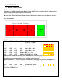
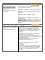
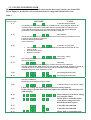
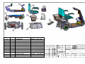
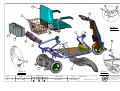
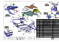
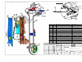
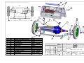
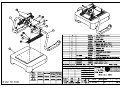
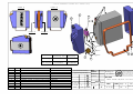
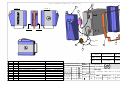
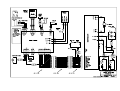
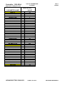
MAINTENANCE INSTRUCTION FOR Superlight SL-3
1.1
General instruction
WARNINGS
1. During maintenance operation on SL-3
Mechanical systems - (i.e., motor and wheel) disconnect the connectors from the batteries to avoid
casual operation.
2. During each electrical test, lift the one rear wheel by
means of block and avoid touching moving parts.
3. All technical operations for the SL-3 should be done only
by trained and authorized technician.
The following are instructions for the technician receiving the SL-3 for normal service or for
repair.
1. During the SL-3 service, the vehicle should be parked on a level
surface, with the key switch disengaged.
2. Prior to the beginning of work, check the vehicle for initial troubleshooting.
3. When the SL-3 is entering for repair, troubleshooting the vehicle using in chapter 1.3 .
4. When the SL-3 is entering for general check or preventive maintenance, review this
maintenance instruction for supporting information.
1.2 List of specific tools
a. Standard technician tool box (wrenches, screw drivers, hexagon socket
screws key set, etc.).
b. Multimeter (Voltmeter) and Amphometer.
c. Steel band for wires inserting
d. Terminals extractor
N0 load test and driving test
This test is very much recommended when there is a suspicion of Transaxle-Power-Unit parts
faults , or when irregular noises are coming from the Power-Unit . Also when there are
complains about too short travel distance, or battery faults.
For these Tests Connect a DC current meter on the Battery Red Positive (+) Power wire. It is
recommended to use an induction current meter (So that no physical connection is needed) .
Make sure the meter wires are far away from any moving parts. The meter Range needed is up
to 40 Amperes .
For No load test use appropriate wood blocks lift the one or two rear wheels of the SL-3 up, so
that they are free to turn without touching the floor . Squeeze the speed lever to maximum and
run the breeze for 1-2 minutes before measuring . Than measure the current consumption
should be between 2.5A to 3A .
For Drive test load drive the SL-3 at full speed on level surface with a user weight of 70-80 Kg
(154-176 lbs) . Than measure the current consumption should be between 6A to 7A .
1
1.3 Mechanical troubleshooting
You have attached full set of drawings include full instruction how to assemble and order
every part of the SL-3
(every drawing will be open by touch as PDF file)
More drawings can be find in the CD
SL-3 assembly for service
- FTSL999
Frame assembly
- ASSL003
Tiller assembly
- ASSL005
Gear-motor-e.m.b assy.
- ASSL021 + ASSL001
Speed control assembly
- ASSL011
Seat fold assembly
- ASSL030
Battery right 18A assembly
- ASSL015
Battery Left 18A assembly
- ASSL016
Elec. house assembly
- ASSL008
Cover electronic assy.
- ASSL014
Speed control assy.
- ASSL011
Front wheel assy.
- ASSL007
Rear wheel pneumatic assy. - ASSL018
Cover power unit assy.
- ASSL017
This paragraph discusses the SL-3 mechanical troubleshooting and repair procedures
No. Symptom
Probable Cause
Remedy
1
- Excessive wear of the
rear wheel or broken.
- Replace the rear wheel
ASSL021 refer to drawing
2
3
4
5
6
7
Excessive
tolerance of the
rear wheel.
When squeezing
Operating Lever
(either left or right)
and releasing it,
the Lever does not
return to the
neutral position.
Excessive noise
from the gear.
- The Lever (internal)
- Spring is broken or
displaced.
- Replace broken spring or
damaged assembly, refer to
ASSL011 drawing.
The adjustment of poten.
Is out of order
Adjust the potentiometer
- Broken gear, excessive
wear of gear wheel and
bearing damage.
Main harness damaged
- Replace motor, gear or e.m.b
refer to drawing ASSL021
and drawing ASSL001
No power
Replace the main harness
Refer to drawing ASSL003
The connectors on the tiller Replace the connector see
or on the battery damage
drawings ASSL005 ASSL015
ASSL017
Head light doesn't Light bulb
Open the rear motor cove
operate
Replace the bulb, see drawing
ASSL014
The tiller is too free The adjustment of the shaft Adjust the bearing nut
or too stiff
bearing not good
See drawing ASSL006
Battery
Replace battery See drawing
ASSL015 + ASSL016 (for 18A)
ASSL024 + ASSL025 (for 26A)
2
1.4 Electrical troubleshooting
CONTENTS
1. PANEL DISPLAY
1.1 Battery Gauge Display
1.2 Status LED indicator
2. HEADLIGHT
3. HORN
4. LOW / HIGH SPEED CONTROL
5. CHARGING
6. PARKING BRAKE ASSEMBLY
7. THE MOTOR HARNESS
8. THE THROTTLE POTENTIOMETER
9. OPERATIONAL TESTS
9.1.Performing operational test using the handheld programmer
10. DIAGNOSTICS
10.1 Diagnosing and troubleshooting using programmer diagnostics mode
11. PROGRAMMING
12. REPLACEABLE PARTS LIST
13. ATTACHMENT : a. parameters listing
b. Electric diagram SL-3.
c. Control and display boards.
3
1. PANEL DISPLAY
1.1 Battery Gauge Display
The Panel Display comprises an accurate Battery Gauge Display and a Status indicator.
When the key switch is turned on the Battery Gauge displays the remaining capacity of the batteries
and the Status led provides diagnostics information.
1.1 Battery Gauge Display
By using four led bars the Battery Gauge Display indicates how much charge is left in the scooter’s
batteries.
Fig1. Panel Display
Table 1
LED 4 LED 3
LED 2
LED1
ON
ON
ON
ON
Battery Remaining
Capacity % (BRC)
80%< BRC <100%
OFF
ON
ON
ON
60%< BRC < 80%
OFF
OFF
ON
ON
40%< BRC < 60%
OFF
OFF
OFF
ON
20%<BRC < 40%
OFF
OFF
OFF
Flashes BRC% < 20%
OFF
OFF
OFF
Flashes POWER SAVE MODE
If the throttle remains in neutral beyond 20 minutes the controller powers down.
The led 1 flashes and the Status led is turned off. (parameter “Sleep Dly” is 20)
Normal operation resumes when the key switch is turn off-turn on.
If the flash not stop – charge the battery for 10 minutes, or change the parameter Sleep Dly to “o”
The new model (serial no. after 01800) the parameter “Sleep Dly” is adjust to “o”
OFF
OFF
OFF
OFF
CHARGING MODE
During charging the Battery Gauge Display and the Status indicator go off.
The drive is inhibited too.
4
FAULTS TROUBLESHOOTING
OFF
OFF
OFF
Flashes
After charging the Battery gauge
display still indicates low battery
capacity by flashing the last led.
The Status indicator is steadily
turned on.
One of the following faults may cause
this problem:
FAULT
1.Open wire fault –replace the cable that connect the
controller with the Front board
2. Inaccurate gauge meter operation- replace the controller
3. Inaccurate battery gauge display operation - replace the
Front Board
4. Incorrect charging – replace the charger
5. The batteries were charged not through the scooter
charging circuitry.
Connect the batteries to the scooter electrical hardness and
plug in the charger.
Wait at least 10 minutes. Unplug the charger and turn on
the key switch if necessary. You should see the full capacity
indication.
OFF
OFF
OFF
OFF
The Key Switch is turned on but the
electric system on the scooter seems to
be “dead”.
The Status led indicator is off.
FAULT
1.Check if the batteries are connected and the circuit
breakers were reset. If the circuit breaker is defective the
voltage will not pass through to the front end of the
scooter. Take a voltage reading at each individual battery.
2.Check if the power cord is plugged into the tiller
receptacle.
3.Check the power harnesses that run along the chassis.
Unplug the front to rear power cord.
Take a volt reading across the two outside pins on the
power plug that must connect to the tiller. You should read
the total battery voltage.
4.Check the connections between Front board and
Charging board adapter (T1, T2, T3).
5.Check the connections at B+ and B- Controller’s
terminals
6. F1 tripped.
Replace the Front board or check and replace the fuse F1.
7. Check the key switch and the battery voltage path the
battery voltage. The battery voltage that is sent to the
Front board is returned back to Front board and
controller.
5
1.2 STATUS LED INDICATOR
The diagnostics information can be obtained observing the fault codes issued by the Status LED.
First it displays a fast flash for 10 seconds then flashes a 2-digit fault identification code.
Table 2
A
B
LED CODE
TWO DIGITS CODE
C
FAULT
(1, 1)
Controller thermal cutback
Overheating can occur if the controller is overloaded or the electromagnetic brake is not
releasing properly. The main current limit decreases steadily until it is reduced to zero.
At the reduced performance level the vehicle must be parked. Full current limit and
performance return automatically after the controller cools down.
Throttle fault
(1, 2)
The throttle potentiometer is connected at the Front board by blue, green and brown wires
1.check for open and short circuits pins
2.defective throttle potentiometer
3.loose connection
(1,3)
1.
2.
3.
(1, 4)
Controller or wiring fault
The cable connecting the Controller with the Front board has interrupt the wire
between 18-18
Defective Front board
Defective Controller
Low battery voltage
The voltage batteries decreases at 17V limit and less than this limit.
The drive is allowed.
HPD fault
(3, 1)
Improper sequence of throttle and the Key Switch or throttle out of calibration.
The high –pedal-disable (HPD) feature prevents controller outputs if the controller is turned on
when the throttle is not in neutral. After 10 seconds of a continuous HPD fault driving is
inhibited until power to the controller is cycled
(3,2)
Electromagnetic brake fault
(3, 4)
Electromagnetic brake fault
Check for a short circuit between wires of the brake coil or for open wires.
The drive is inhibited.
Replace the electromagnetic brake assembly.
Controller failure or low battery voltage
(3,3)
Check the voltage across the batteries (the total voltage battery)
If the voltage is greater than 21V then replace the controller otherwise proceed
with charging.
(4, 4)
(4,2)
Short in motor or in motor wiring
or Controller failure
Motor fault or controller fault
or the motor voltage does not
match the throttle request
(2, 1)
Controller internal fault
(2, 2)
Controller internal fault
(4, 1)
Motor fault or Controller fault
6
2. HEADLIGHT
During charging the Headlight is not operable.
The headlight doesn’t operate
Check and replace if necessary the headlight beam
lamp
Check the fuse F2
The fuse F2 is mounted on the Front board
Take a volt reading from each side of the fuse to
GND. As GND connection use T3. If either of the
readings is zero volts replace the Rear board.
If one of readings equals the voltage battery and the
second indicates zero volts replace the fuse F2.
F2 is specified as:
Slow Blow type fuse 1A / 250V
P/N:218.001 or P/N: 215.001
LITTELFUSE
Check the connections between the Light switch and
the Front board
Replace the Light switch.
Check wire-to-wire connection between the Headlight
assembly and the Front board.
The lights can be operated during charging
Front Board faulty
3. HORN
Horn does not operate when the
pushbutton is depressed
Horn doesn’t operate when driving
reverse direction
Horn does not operate when the
brake is manually released
Horn does not beep on fault
condition
Check for reverse wiring connection
Check the push button connection
Push button faulty
Connect the jumper between header’s terminal 2 and 3. The
JP1 header is mounted on the Front board.
Check and repair when necessary the micro-switch wires
continuity
When manually release the brake check if the micro-switch
will close its contacts. If not replace the brake assembly.
Replace the Front board.
Check the horn connections and reverse if necessary.
Replace the horn.
Move the jumper between terminals 2 and 3 of the header JP1.
Use the handheld programmer and change the value of
parameter “FAULT BEEP” from OFF to ON.
7
4. LOW / HIGH SPEED CONTROL
The switch selects the driving mode (maximum speed limited at 60% or no limit)
High speed mode = the switch’s contacts are closed and the lamp illuminates
Low speed mode = The switch’s contacts are opened and the lamp is turned off.
The scooter does not travel at full speed and
the battery condition is good
Turning the switch into Fast position blows
the fuse F1 located on the Front board
The switch is working in reverse way
Indifferent how the switch is set the lamp
glows continuously
1.Check connections of the switch with the Front
board. The connections must fit the following table:
Switch 1A
Black
Six circuits plug pin- 6
Switch 1
White
Six circuits plug pin-5
Switch 1B
Red
Six circuits plug pin-4
2.Check cable that connect the Controller with the
Front board; check the continuity of wire that runs
between 8-8 each connector.
4. Replace the Front board
5. Replace the Controller
Red wire is reversed with White wire
Red wire is reversed with Black wire
Black wire is reversed with White wire
5. CHARGING
Indifferent which position is selected for Key Switch the system automatically will detect if the
charger outlet is plugged into the vehicle’s charging socket and the panel display is shut off.
The drive and lights functions are not allowed.
The charging current is routed via the controller, scooter’s power cord, the sixteen wires cable,
Front board and the Charging board adapter. The charging circuit is protected by a manually
resettable 4Amp circuit breaker. The charging average time may be about 10 hours.
AC power is plugged in and the charger DC
outlet is connected to the scooter’s socket but the
charger’s display flashes informing the battery
side is not connected
1.Check circuit breaker status. Take a volt
reading from one of the metal tabs on the bottom
of the circuit breaker to the most negative
battery terminal (GND). If either of the readings
is different than the total battery voltage reset or
replace the fuse.
2.Check the connections between Charging
Adapter board and Front board
T1
T2
T3
RED
BLUE
BLACK
T1
T2
T3
3.Charging socket damaged.
Replace the Charging Adapter board
8
4.Faulty charger
After full charging the Battery Gauge Display
indicates battery capacity different than 100%
If the battery gauge reading seems to fall more
quickly than usual or the travel distance between
two consecutive charging decreases more quickly
than usual proceed as follows:
5.Check the batteries connections and status of
each circuit breaker included in the battery pack
.
1.Incorrect charging. The charger was left
connected less time than necessary. The user
must wait the green indication of the charger’s
display
2. Charger is not operating properly
3. The batteries were charged in other place not
mounted to the vehicle
4. Defective controller
5. Defective Front board
6. Defective Display module
1. Replace batteries
2. Replace charger
3.Potential mechanical problem.
Check the gear –motor and the electromagnetic
brake
6. PARKING BRAKE ASSEMBLY
A micro-switch is attached to the parking brake so that when the brake is manually released the
system is inhibited and will not drive
How is tested the electric continuity of
Switch off the power.
the brake coil?
Unplug the 4-pin connector with two black and two
white wires from the header J3 located on Front
board.
Turn your meter to ohms or resistance scale.
Take a resistance reading from black to black.
A reading of approximately 65 ohms should appear.
How to check if the micro-switch is
While motor cap knob set in normal position take a
working properly?
resistance reading from white to white wire. The
micro-switch should be open. Turn clockwise the
motor cap knob. The micro-switch is closed and the
meter reads 0 ohms.
How is tested the brake voltage output?
Turn on the scooter. Ensure the brake assembly
connector is plugged into J3 header located on the
Front board. Take a volt reading across the brake
coil by pushing the red probe into the terminal 1 of
the connector J3 and black probe into the terminal 2
of the same connector.
The voltage brake should jump to the total battery
voltage as soon as the throttle is depressed in either
direction. The brake assembly is always locked until
voltage is applied to it. When voltage is applied to the
brake coil a magnetic field is generated.
The magnetic field pulls away a plate that locks
the brake into place and allows the motor to spin
freely. You must be able to hear the parking brake
operate within a few seconds.
9
No drive and the Status indicator flashes
(3, 2) code
1.Check if brake connector is plugged into J3 header.
Switch power off and perform the brake coil
continuity test. If the reading does not appear
correctly check for open or shorted wires. If they are
good replace the brake assembly.
2.Switch the power on and perform the voltage brake
output test. If the reading does not appear correctly
one of the following parts could be faulty:
- Cable that connects the controller with the
Front board
- Controller
- Front board
Excessive heat on the brake body
The brake assembly is mechanically damaged.
Replace the brake assembly
Perform the micro-switch test If the micro-switch
operates properly replace in the follwing order: Front
board, cable between Front and Controller board and
final the Controller.
When turn the cap motor knob to
release brake the horn doesn’t sound
and the driving is not inhibited
7. THE MOTOR HARNESS
How to check the controller output?
Measure the voltage between controller’s
terminals M1 and M2.
When is selected Forward direction M1 will be
more positive than M2 and the voltage read is
approximately 1.5V less than the total battery
voltage. With the throttle bar fully depressed in
Reverse you should see a negative reading of
about 60% of the total battery voltage.
How to connect the gear-motor?
Connect Yellow cable to M2 controller’s
controller terminal and Brown cable to M1
The controller output appears to be normal but Disconnect the yellow and brown cable from
the performances are lowered or the motor
the controller side. Turn your meter to an ohm
doesn’t run any more.
or resistance scale. Place the red probe of your
meter on the yellow wire’s terminal and the
black probe on the brown wire’s terminal.
Take the resistance reading across the motor.
A reading between 0.3ohm and 2-4ohm should
appear. If the reading is higher than 4 ohm
replace the brushes. DC brush wear is the
result of mechanical friction and electrical
corrosion.
If the reading indicates an open circuit
armature try first replacing the brushes. If
nothing happen replace the motor.
The driving speed forward direction is less
than the speed in reverse direction
Check and correct the connections at M1 and
M2 or wiring to motor. This problem occurs if
the cables yellow and brown are reverse
connected.
10
8. THROTTLE POTENTIOMETER
The throttle controls both the speed and the direction of the scooter. Pushing the throttle in one
direction the scooter moves forward and pushing in the other the scooter moves reverse
Usually Forward is on the right hand
and Reverse on the left hand. How can
we reverse them without loosing
performances?
Is the potentiometer correct
calibrated?
The throttle potentiometer is connected to Front board
by one six –pin connector plugged into J4 header
located on front board.
Reverse Blue and Brown wires. In this case depressing
the throttle with the left hand will select forward and
the reverse direction will be selected using the right
hand. Change the label of the for front and back !!
Turn the power off.
Unplug the connector inserted in the header J4 located
on the front board.
Without depressing the throttle take the following
resistance readings:
- 1. Blue and Green
- 2. Green and Brown
- 3. Blue and Brown
The value of the potentiometer resistance may
range between 4.8Kohm and 5.2Kohm.
1
You should see 2400 – 2600 ohm
2
You should see 2400 –2600 ohm
3
You should see 4800 –5400 ohm
If the issues 1 and 2 have as result almost the same
values then the potentiometer may be correctly
centered within the controller’s neutral dead-band.
If a voltage reading is preferred turn the power on
and connect a voltmeter. Take three successive
readings. The red probe is pushed first into
terminal 2 of the J4 (Green wire) then into
terminal 1 (blue wire) and finally into terminal 3
(brown wire).
The black probe is pushed into terminal 4 of the
same connector J4 (GND).
Without depressing the throttle the following
readings should appears:
Terminals Value
1 and 4
2 and 4
3 and 4
The Status led indicator indicates
throttle fault
About 4.5V
About 2.5V+/100mV
About 0.4V
Front board
header
J4
J4
J4
Perform throttle potentiometer test as describe above.
The goal of the test is to find out wires that are short11
While depressing the throttle to
maximum with Forward Full speed
selected the controller output voltage is
less then 100%( total battery voltage
less 1.5V)
circuit, loose connections, no calibrated or damaged
potentiometer. If they are good carry out test of the
cable that connects controller with front board.
Otherwise replace the Front board or replace the
Controller.
Ensure the switch Low /High SPEED is working
correctly.
The controller should be reprogrammed.
The value of the parameter THRTL GAIN should be
increased in order to fit the electric span of the throttle
potentiometer with the controller.
9. OPERATIONAL TESTS
9.1. PERFORMING OPERATIONAL TESTS USING THE HAND-HELD
PROGRAMMER.
The programmer is a menu-driven device powered by the host controller via a 4-pin connector
located on the controller. The handheld programmer allows programming, testing, and
diagnosing the controller.
A
Connect the hand-held programmer
B
Turn the key switch on. The programmer should power up with an initial display. It
displays the controller’s model number, date of manufacture and software release.
Notice the software release number. The last one is 06.
C
Put the programmer in TEST mode by pressing the <TEST> key.
The LED at the corner of the key lights up.
Four lines of the menu are displayed at a time.
Scroll down within the menu until the desired item is positioned on the four lines
window.
12
D
E
F
G
H
HEATSINK C
value
THROTTLE %
SPD LIMIT POT
value
100
BATT VOLTAGE
value
BDI
value
MODE INPUT A
ON
OFF
REVERSE INPUT
INHIBIT IN
OFF
OFF ON
EM BRAKE DRV
ON
OFF
MAIN CONT
ON
OFF
Value means controller internal temperature. If
displayed value exceeds 92-Celsius degrees the
controller will enter the thermal protection.
Value means percent of applied throttle.
Constant value 100.
Faulty system or controller if different than 100.
The actual total battery voltage when throttle is
applied
Value means percent of battery remaining capacity.
Full charged battery means 100%
The reading could be ON or OFF depending of
Low /High SPEED switch
Constant value OFF; not used in application
The reading could be On or OFF.
When reading is ON the drive is inhibited
The reading could be On or OFF. With throttle
applied the value is ON. When releasing the throttle
the value is changed to OFF
Displays the status of the main relay located in the
controller. With throttle applied the status should be on.
If it remains off the controller has detected a fault and
the driving is inhibited
Constant value
OFF; not used in application
400
MOTOR R
OFF
PUSH ENABLE IN
Before tests enter the Programming mode and change the parameter THRTL
AUTOCAL from OFF to ON.
Other alternative is putting the vehicle’s front wheel in freewheeling mode.
LOW /HIGH SPEED SW
Turn the switch into Low Speed position. The switch’s lamp is off. The LCD shows
MODE INPUT A OFF. Turn the switch into High Speed position. The switch’s lamp
glows. The LCD shows MODE INPUT A ON.
INHIBIT TEST
Plug in the charger’s DC outlet into the charging socket. Panel display turns off.
The handheld programmer LCD shows that INPUT IN was changed from OFF to ON.
Take out the charger’s plug and turn the motor cap knob to release the parking brake.
The horn warns continuously and the LCD shows INPUT IN ON. The panel display
works normally indicating the battery remaining capacity and controller status.
Throttle mechanical and electrical span test
Squeeze the throttle (operation lever) in either direction. You should notice:
9 the motor turns forward or reverse direction
corresponding which way you operate the throttle.
9 the motor should run proportionately faster with
increasing throttle.
9 the handheld programmer’s LCD shows:
MAIN CONT ON
EM BRAKE DRV ON
THROTTLE % increasing and decreasing value shown
9 ensure that at maximum lever’s mechanical travel the reading is 100%
Battery voltage reading
While throttle is applied the handheld programmer’s LCD shows the total voltage
battery.
13
10. DIAGNOSTICS
5.1 Diagnosing and troubleshooting using programmer diagnostics mode
Connect the programmer. Turn the key switch on. Press the DIAGNOSTICS key.
The display should indicate NO FAULTS FOUND. If there is a problem the Status indicator will
flash a diagnostic code and the programmer will display a diagnostic message.
List of messages:
You should read the explanations included in the paragraph 1.2 too.
PROGRAMMER DISPLAY
THERMAL CUTBACK
THROTTLE FAULT 1
SPD LIMIT POT FAULT
LOW BATTERY VOLTAGE
MAIN OFF FAULT
MAIN ON FAULT
MAIN CONT WELDED
MAIN ON FAULT
PROC / WIRING FAULT
PRECHARGE FAULT
HW FAILSAFE
EEPROM FAULT
NO KNOWN FAULTS
POWER SECTION FAULT
HPD
EXPLANATION
Cut back due to over-temperature
Throttle input voltage out of range
Loose connection
Front board faulty
Controller faulty
Battery voltage too low
Main controller driver fault
Main controller driver fault
Main controller driver fault
Main controller driver fault
HPD fault is present more than 10s
The fault caused by misadjusted
potentiometer, broken throttle
potentiometer or broken throttle
mechanism
Controller failure or low battery
voltage
Motor voltage fault
EEPROM Fault-controller faulty
Status Led code
(1,1)
(1, 2)
(1, 3)
Check controller and motor power
connection
The HPD feature prevents
controller output if the vehicle is
powered when the throttle is not in
neutral. If the controller latches
cycle the key switch for resuming.
(4, 4)
(1, 4)
(2,1)
(2,4)
(2, 2)
(2, 4)
(3,1)
(3, 3)
(4, 2)
(4, 3)
(3, 4)
EXAMPLE 1
Symptom: the scooter appears to run only in reduced speed range.
The handheld programmer set in Diagnostic mode indicates NO KNOWN FAULTS.
Put the programmer in TEST mode and scroll down to observe the line MODE INPUT A.
Turn the switch LOW / HIGH switch into LOW position.
You should see MODE INPUT A OFF. Turn the switch into HIGH position. You should see
MODE INPUT A ON. If the reading does not appear correctly proceed by:
- Checking the cable that interfaces Front board with the Controller.
- Checking the switch connection with Front board
- Checking and replacing the switch
If the reading is correct then replace the controller.
14
EXAMPLE 2
Symptom: After charging the battery gauge display indicates less than 20% remaining capacity by
flashing the LED 1.
Powered up the scooter. Connect the handheld programmer and select DIGNOSIS mode
The handheld programmer displays NO KNOWN FAULTS.
Select TEST mode.
Scroll down to observe the line BDI value. If the value is 100%:
9 Check and replace the cable that interfaces the controller with the front board
9 Replace Front board
9 Replace the cable that connect Front board with Display board
9 Replace Display board
If the handheld programmer shows BDI 0% you should check the charging electric circuitry
(wiring, charging board adapter board, charging fuse, power cabling and battery connections).
After performing this test connect the charger and powered it up.
When Green led charger’s indicator is turned on state take a reading of the total battery voltage.
If the value shown is greater than 26V during at least 10 minutes and BDI value remains 0% you
have to replace the controller. If you observe BDI value updates from 0 to 100 percent turn off
the scooter. Wait for 3 to 5 minutes and turn it on and read BDI value again. If BDI line shows
0% the controller is defective. If the BDI shows 100% the problem resides in incorrect charging
or defective charger.
11. PROGRAMMING
In PROGRAM mode, accessed by pressing the PROGRAM key all the adjustable parameters
are displayed four at a time along with their present settings.
You can drive with the handheld programmer connected. For safety reasons accessing some
critical parameters will cause the controller to trip. This is intentional and the controller can be
simply reset by switching off and on again.
Resetting parameters to non-compatible values could result in an unsafe set-up of the vehicle and
for the user. The recommended values are included in the listings release
Contact our company if you need any advice in programming.
12. REPLACEABLE PARTS LIST:
Controller
- PC00121 or PC00099
Front Board
- PC00100
Charger board
- PC00106
Display board
- PC00103
F1 SMT fuse slow blow 2.5A – FU00010
F2 slow blow fuse 1.25A
– FU00005
15
I:\RD\SL-3\DRAWINGS SL3(PART,ASSY.,WIRING)\assy\
1
10
2
3 4
7 8
9
11
5
6
12
1
USER MANUAL ENG. SL-3
PRSL001
11
1
CHARGER 2A
FT00232 + supply cable
10
1
SEAT SL-2 BLACK ASSY.
ASSL030 (See page 7)
9
1
REAR BASKET SL-3 ASSY.
ASSL028
8 (option)
1
BATTERY LEFT 24H AS.
ASSL025
7 (option)
1
BATTERY RIGHT 24H AS.
ASSL024
6
1
POWER UNIT SL-3
ASSL021
5
1
BATTERY COVER SL-3 ASSY.
ASSL020
4
1
BATTERY LEFT 18H SL-3 AS.
ASSL016
(See page 9)
d
3
1
BATTERY RIGHT 18H SL-3 AS.
ASSL015
(See page 8)
c
Do not scale from drawing.
(See page 6)
Approved only with stamp
e
2
1
TILLER SL-3 ASSY.
ASSL005
(see page 5)
1
1
FRAME SL-3 ASSY.
ASSL003
(See page 4)
ITEM.
QTY.
NAME
PART/NO
DRAW/NO
b
15-7-04
x
a
Date.
Conf.
Update.
Draw.
Checked:
Production:
Confirme:
Michael
AFIKIM ELECTRIC MOBILIZERS
Drawing no.
KIBUTZ AFIKIM 15148 ISRAEL
TEL:972-4-6754814 FAX:972-4-6751456
E-mail: [email protected]
Website: www.afiscooters.com
FTSL999a
Part name:
SUPPERLIGHT SL-3 ASSY.
Tolerance.
Linear
Angular
0.3
1
Date
15-7-04
Scale
Page:
1
Of:
9
Cat. No.
FTSL001
I:\RD\SL-3\DRAWINGS SL3(PART,ASSY.,WIRING)\assy\
10
1n
1p
1e
2
9
B
DETAIL A
SCALE 1 : 2
1
A
8
7
4
1k
C
3
10d
6
5
DETAIL B
SCALE 1 : 4
Page:
Of:
2
9
DETAIL C
SCALE 1 : 4
DATE
Scale
26-7-04
X
tolerance
holes dia. linear angular
0.3
0.1
1
Drawing no.
FTSL999a
Cat. No.
FTSL001
Part name:
SUPERLIGHT SL-3
AFIKIM ELECTRIC MOBILIZERS
KIBUTZ AFIKIM 15148 ISRAEL
TEL:972-4-6754814 FAX:972-4-6751456
E-mail: [email protected]
Website: www.afiscooters.com
I:\RD\SL-3\DRAWINGS SL3(PART,ASSY.,WIRING)\assy\
REAR-SUPPLY SL-3
ASSL015
+
-
ASSL016
red
AS00653
BATT.12V18AH
P/N 2000520
+
-
SW00017
AS00746
AS00620
BATT.12V18AH
P/N 2000520
FRONT-TILLER SL-3
red
yellow (2)
1a
brown (1)
FU00017
1
1b
1b
black
PC00106
red
AS00619
red
AS00652
1
red (4)
brown (3)
green (2)
AC00087
black
AS00654
1a
1
black (6)
white (5)
FU00017
ACSL027
SW00016
1
3
PC00103
blue (1)
ASSL022
red - AS00639
white/org
2
4
2
ASSL027
1
blue - AS00641
black - AS00640
3
4
white
green
3
AS00645
red (4)
black (3)
yellow (2)
brown (1)
red
black
AS00638
FU00014
ELSL001
AS00639
red
black
white
purple
PC00121
yellow
brown
Of:
9
DATE
26-7-04
Scale
8
4
green
X
0.3
0.1
1
1
321
5
black
purple
white
PC00100
ASSL004
tolerance
holes dia. linear angular
4
AS00637
white/org.
ASSL026
3
2
3
1
red
blue
white
Page:
4
red
green
MOSL001
AS00616
Drawing no.
FTSL999a
ASSL009
Cat. No.
FTSL001
Part name:
SUPERLIGHT SL-3
AFIKIM ELECTRIC MOBILIZERS
KIBUTZ AFIKIM 15148 ISRAEL
TEL:972-4-6754814 FAX:972-4-6751456
E-mail: [email protected]
Website: www.afiscooters.com
I:\RD\SL-3\DRAWINGS SL3(PART,ASSY.,WIRING)\assy\
3
5
1
DETAIL I
SCALE 1 : 3
15
18
2
12
10
11
13
16
6
17
22
DETAIL K
SCALE 1 : 3.5
15
14
18
23
7
16
17
I
K
8
M
L
DETAIL L
SCALE 1 : 3
19
8
19
J
18
8
Page: 4
Of:
9
DATE
Scale
6-5-04
X
DETAIL J
SCALE 1 : 3
4
tolerance
holes dia. linear angular
0.3
0.1
1
20
23
22
21
20
19
18
17
16
15
14
13
12
11
10
9
8
7
6
5
4
3
2
1
NO.
Drawing no.
Cat. No.
FTSL999a
ASSL003
DETAIL M
SCALE 1 : 3
19
9
8
0.40m
9
1
1
5
4
1
1
1
1
1
1
1
1
9
5
1
1
1
2
1
1
1
QTY.
strap 70x25(x4) , 50x25(x2)
RIVET 5/12
MAIN HARNESS SL-3 (see page 3)
FRAME SL-3
CLAMP MAIN HARNESS SL-3
PLASTIC PIN D=4.7
SCREW HEX. M8X50 GALV.
WASHER M8
NUT HEX.NYLON M8 GALV.
SEAT BASE ADAPTOR SL2
SCREW M6X45
CLIP PLASTIC BAT. COVER
NUT HEX.NYLON M6 GALV.
CLIP PLASTIC BUSHING
WASHER GALV. M5
RIVET 4/12 BLACK ANODIZE
PLASTIC FLOOR SL3
MUD GURD
CARPET
SCREW CAP M6*8+GALV.
SPRING LIMITER SUPERL.
COVER PLAST STEERING SPRING
SPRING LOCK STEER PIN
NAME
Part name:
FRAME SL-3 ASSY.
AC00132
SC00250
ASSL004
MPSL001
HW00120
HW00092
9010398
WA00057
9010311
MP00588
9010177
IP00033
9010181
IPSL004
WA00002
9010352
VPSL003
VP00106
HWSL001
SC00042
MP00442
IP00043
SP00004
PART/NO
18
ASSL004*
MPSL001*
MP00588*
SC11014*
VPSL003*
VP00106*
MP00442*
IP00043*
SC11013*
DRAW/NO
AFIKIM ELECTRIC MOBILIZERS
KIBUTZ AFIKIM 15148 ISRAEL
TEL:972-4-6754814 FAX:972-4-6751456
E-mail: [email protected]
Website: www.afiscooters.com
I:\RD\SL-3\DRAWINGS SL3(PART,ASSY.,WIRING)\assy\
WHITE
BLACK
C (1 : 3)
8
6
9
RED
WHITE
9
C
BLACK
12
7
3
5
11 10
13
4
13
1
15
14
13
12
11
10
9
8
7
6
5
4
3
2
1
ITEM
15
14
14
2
1
8
2
2
1
1
1
1
1
1
1
1
1
1
1
QTY.
Do not scale from drawing.
Approved only with stamp
e
SCREW R/H PHILIP M4*10
SCREW PAN PHL.TAP.4.2*9.5
SCREW PHILIPS M4X12
GRIP F/HANDLE RUBBER MATR
CONEC. 4P CVILUX
CONEC. 6P CVILUX
LIGHT SW.CON. SL2 ASSY.
COVER SP.CO. SL-3 ASSY.
COVER BO.SP. SL-3 ASSY.
SPEED CON. SL-3 ASSY.
COVER ELECT. SL-3 ASSY.
ELECTRIC SYST. SL-3
ELECTRIC HOUSE SL-3
FRONT WHEEL SL-3 ASSY.
TILLER FRAME ASSY. SL-3
NAME
Draw.
Checked:
Production:
Confirme:
Michael
b
18-3-04
x
a
Date.
Conf.
Update.
AS00619*
ASSL013*
ASSL012*
ASSL011*
ASSL014*
ASSL010*
ASSL008*
ASSL007*
ASSL006*
DRAW/NO
AFIKIM ELECTRIC MOBILIZERS
Drawing no.
KIBUTZ AFIKIM 15148 ISRAEL
TEL:972-4-6754814 FAX:972-4-6751456
E-mail: [email protected]
Website: www.afiscooters.com
FTSL999a
Part name:
d
c
SC00173
SC00085
SC00056
VP00026
CO00083
CO00080
AS00619
ASSL013
ASSL012
ASSL011
ASSL014
ASSL010
ASSL008
ASSL007
ASSL006
PART/NO
TILLER SL-3 ASSY.
Tolerance.
Linear
Angular
0.1
1
Date
18-3-04
Scale
Page: 5
Of:
9
Cat. No.
ASSL005
2
13
I:\RD\SL-3\DRAWINGS SL3(PART,ASSY.,WIRING)\assy\
356
14
22
256
9
22
545
3
10
11
12
1
5
15
6
8
15
14
13
12
11
10
9
8
7
6
5
4
3
2
1
ITEM
2
2
1
1
1
1
1
1
2
2
2
1
2
1
1
QTY.
SCREW HEX.M8x1x20 (FINE THREAD)
SCREW ELL .CUP+WASH .M6*50 GALV.
HANDLE F/COVER SL -3
HEX.LOCKNUT M5
SCREW HEX.M5*16 GALV.
PLATE 2 HOLES SL -3
PLATE 1 HOLE SL-3
SPIRAL PIN 5*35
SCREW SHAFT R\ /R/H ALLEN 8*30+M6
CUP F/SUPERLIGHT WHEEL
METAL CLAMP PO .UN.SL3
CLAMP RELEASE SL -3 ASEA
REAR WHEEL SL -3 ASSY .
COVER F /POWER UNIT SL -3 ASS .
POWER UNIT SL 3
PART NAME
SC00249
SC00242
MPSL012 MPSL012*
9010317
9010315
MPSL014 MPSL014*
MPSL015 MPSL015*
SC00233
SC00224
IPSL005
MPSL010
MPSL 010
ASSL 019
ASSL 019*
ASSL 018
ASSL 018*
ASSL 017
ASSL 017
ASSL 001 ASSL 001*
Catalog no . Drawing No .
4
7
Do not scale from drawing.
Approved only with stamp
e
Draw.
Checked:
Production:
Confirme:
Michael
FTSL999a
c
20-4-04
b
8-3-04
x
a
Date.
Conf.
Update.
KIBUTZ AFIKIM 15148 ISRAEL
TEL:972-4-6754814 FAX:972-4-6751456
E-mail: [email protected]
Website: www.afiscooters.com
Part name:
d
6-6-04
AFIKIM ELECTRIC MOBILIZERS
Drawing no.
POWER UNIT SL-3 ASSY.
Tolerance.
Linear
Angular
0.1
1
Date
8-3-04
Scale
Page: 6
Cat. No.
Of:
ASSL021
9
I:\RD\SL-3\DRAWINGS SL3(PART,ASSY.,WIRING)\assy\
VIEW A
8
7
VIEW B
PORTALAC
6
3
R
4
(-)
VIEW B
VIEW A
5
(+)
R
BLACK
RED
Name
Catalog No. Battery
18A Right ASSL015
2000520
21A Right
10
9
8
7
6
5
4
3
2
1
ITEM
1
1
1
1
1
1
1
1
1
1
QTY.
HEX DOMEND NUT M5
SCREW ALLEN R/H M5*12 GLVA.
COVER F/BAT.REAR 15A
BATTERY 12V, 18/21AH
BAT.COVER LEFT SL2
BAND F/BATTERY SL-3
RUBBER COVER F/FUSE AUTO/ZING
FUSE 30A (ZE-700-30A) +CAP
CONNECT.42179 3P FEMA.
BATT.WIRE SL2 ASSY
NAME
ASSL031
9010444
9010396
2000676
See Table
MP00595
MPSL011
HW00082
FU00017
CO00065
AS00655
PART/NO
10 9
RED
2
1
AC000151
Do not scale from drawing.
2000676*
MP00595*
MPSL011*
Approved only with stamp
e
5-7-04
DRAW/NO
Michael
03-05-04
b
8-3-04
x
a
Date.
Conf.
Update.
AFIKIM ELECTRIC MOBILIZERS
Drawing no.
KIBUTZ AFIKIM 15148 ISRAEL
TEL:972-4-6754814 FAX:972-4-6751456
E-mail: [email protected]
Website: www.afiscooters.com
FTSL999a
Part name:
d
c
CO00065*
Draw.
Checked:
Production:
Confirme:
BATT.RIGHT 18/21A SL-3 ASSY.
Tolerance.
Linear
Angular
0.1
1
Date
8-3-04
Scale
Page: 8
Of:
9
Cat. No.
See Table
I:\RD\SL-3\DRAWINGS SL3(PART,ASSY.,WIRING)\assy\
8
7
6
VIEW A
VIEW B
PORTALAC
3
(+)
L
VIEW B
VIEW A
(-)
RED
RED
2
BLACK
L
10
5
9
1
Name
Catalog No. Battery
18A Left ASSL016
2000520
10
9
8
7
6
5
4
3
2
1
ITEM
1
1
1
1
1
1
1
1
1
1
QTY.
HEX DOMEND NUT M5
9010444
SCREW ALLEN R/H M5*12 GLVA. 9010396
COVER F/BAT.REAR 15A
2000676
BATTERY 12V,18/21AH
See Table
BAT.COVER LEFT SL2
MP00595
BAND F/BATTERY SL-3
MPSL011
RUBBER COVER F/FUSE AUTO/ZING HW00082
FUSE 30A (ZE-700-30A) + CAP FU00017
CONNECT.42179 3P FEMA.
CO00065
BATT.WIRE SL2 ASSY
AS00655
NAME
PART/NO
21A Left
2000676*
MP00595*
MPSL011*
CO00065*
DRAW/NO
Do not scale from drawing.
Approved only with stamp
e
5-7-04
24-06-04
3-05-04
Draw.
Checked:
Production:
Confirme:
Michael
b
8-3-04
x
a
Date.
Conf.
Update.
AC000151
AFIKIM ELECTRIC MOBILIZERS
Drawing no.
KIBUTZ AFIKIM 15148 ISRAEL
TEL:972-4-6754814 FAX:972-4-6751456
E-mail: [email protected]
Website: www.afiscooters.com
FTSL999a
Part name:
d
c
ASSL032
BATTERY LEFT 18A SL-3 ASSY.
Tolerance.
Linear
Angular
0.1
1
Date
8-3-04
Scale
Page: 9
Of:
9
Cat. No.
See Table
LIST OF PARAMETERS
For Afikim
Controller: 1210-2204
Application: Caddy, SL2, SL3
REV 1
12/05/04
Caddy. SL2, SL3
PARAMETER NAME
VALUE
Beeper Sloid
MAIN C/L
MOTOR R
IR COMP COEFF
KEY OFF DECEL
TREMOR COMP
ACCEL MAX SPEED
ACCEL MIN SPEED
DECEL MAX SPEED
DECEL MIN SPEED
E STOP
REV ACCEL MAX
REV ACCEL MIN
REV DECEL MAX
REV DECEL MIN
M1 MAX SPD
M2 MAX SPD
M1 MIN SPD
M2 MIN SPD
M1 REV MAX SPD
M2 REV MAX SPD
REV MIN SPD
GEAR SOFTEN
SOFT START
RAMP SHAPE
BDI FULL VLTS
BDI EMPTY VLTS
BDI RESET TIME
BDI RESET
SLEEP DLY
BRAKE DLY
CREEP SPD
THRTL TYPE
THRTL DEADBAND
THRTL GAIN
THRTL AUTOCAL
SPD SCALER
HIGH PEDAL DIS
FAULT BEEP
SEAT LIFT
BRAKE FLTS
SL BRAKE FLTS
USL
PUSH SPD
OFF
45
100
50
1.2
2
2.6
2.2
0.8
1.2
2
1.2
1
1
1
60
100
30
60
40
50
30
50
40
50
24.6
20.0
10
25.6
0
0.4
6
0
15
1.6
OFF
27
ON
OFF
OFF
ON
OFF
OFF
32
AFIKIM ELECTRIC VEHICLES
CADDY, SL2, SL3
SOFTWARE RELEASE H