1
Vehicle Network Toolbox™
User's Guide
R2015a
How to Contact MathWorks
Latest news:
www.mathworks.com
Sales and services:
www.mathworks.com/sales_and_services
User community:
www.mathworks.com/matlabcentral
Technical support:
www.mathworks.com/support/contact_us
Phone:
508-647-7000
The MathWorks, Inc.
3 Apple Hill Drive
Natick, MA 01760-2098
Vehicle Network Toolbox™ User's Guide
© COPYRIGHT 2009–2015 by The MathWorks, Inc.
The software described in this document is furnished under a license agreement. The software may be used
or copied only under the terms of the license agreement. No part of this manual may be photocopied or
reproduced in any form without prior written consent from The MathWorks, Inc.
FEDERAL ACQUISITION: This provision applies to all acquisitions of the Program and Documentation
by, for, or through the federal government of the United States. By accepting delivery of the Program
or Documentation, the government hereby agrees that this software or documentation qualifies as
commercial computer software or commercial computer software documentation as such terms are used
or defined in FAR 12.212, DFARS Part 227.72, and DFARS 252.227-7014. Accordingly, the terms and
conditions of this Agreement and only those rights specified in this Agreement, shall pertain to and
govern the use, modification, reproduction, release, performance, display, and disclosure of the Program
and Documentation by the federal government (or other entity acquiring for or through the federal
government) and shall supersede any conflicting contractual terms or conditions. If this License fails
to meet the government's needs or is inconsistent in any respect with federal procurement law, the
government agrees to return the Program and Documentation, unused, to The MathWorks, Inc.
Trademarks
MATLAB and Simulink are registered trademarks of The MathWorks, Inc. See
www.mathworks.com/trademarks for a list of additional trademarks. Other product or brand
names may be trademarks or registered trademarks of their respective holders.
Patents
MathWorks products are protected by one or more U.S. patents. Please see
www.mathworks.com/patents for more information.
Revision History
March 2009
September 2009
March 2010
September 2010
April 2011
September 2011
March 2012
September 2012
March 2013
September 2013
March 2014
October 2014
March 2015
Online only
Online only
Online only
Online only
Online only
Online only
Online only
Online only
Online only
Online only
Online only
Online only
Online only
New for Version 1.0 (Release 2009a)
Revised for Version 1.1 (Release 2009b)
Revised for Version 1.2 (Release 2010a)
Revised for Version 1.3 (Release 2010b)
Revised for Version 1.4 (Release 2011a)
Revised for Version 1.5 (Release 2011b)
Revised for Version 1.6 (Release 2012a)
Revised for Version 1.7 (Release 2012b)
Revised for Version 2.0 (Release 2013a)
Revised for Version 2.1 (Release 2013b)
Revised for Version 2.2 (Release 2014a)
Revised for Version 2.3 (Release 2014b)
Revised for Version 2.4 (Release 2015a)
Contents
1
Getting Started
Vehicle Network Toolbox Product Description . . . . . . . . . . .
Key Features . . . . . . . . . . . . . . . . . . . . . . . . . . . . . . . . . . . . .
1-2
1-2
Product Capabilities . . . . . . . . . . . . . . . . . . . . . . . . . . . . . . . . .
Vehicle Network Toolbox Characteristics . . . . . . . . . . . . . . .
Interaction Between the Toolbox and Its Components . . . . . .
Expected Background . . . . . . . . . . . . . . . . . . . . . . . . . . . . . .
Related Products . . . . . . . . . . . . . . . . . . . . . . . . . . . . . . . . . .
1-3
1-3
1-4
1-6
1-6
Install Required Components . . . . . . . . . . . . . . . . . . . . . . . . .
Required Components . . . . . . . . . . . . . . . . . . . . . . . . . . . . . .
Install Devices and Drivers . . . . . . . . . . . . . . . . . . . . . . . . . .
Install the Toolbox . . . . . . . . . . . . . . . . . . . . . . . . . . . . . . .
Supported Hardware . . . . . . . . . . . . . . . . . . . . . . . . . . . . . .
1-7
1-7
1-7
1-10
1-10
Vehicle Network Communication in MATLAB . . . . . . . . . . .
Transmit Workflow . . . . . . . . . . . . . . . . . . . . . . . . . . . . . . .
Receive Workflow . . . . . . . . . . . . . . . . . . . . . . . . . . . . . . . .
1-13
1-14
1-15
Vehicle Network Communication Examples . . . . . . . . . . . .
Prerequisites . . . . . . . . . . . . . . . . . . . . . . . . . . . . . . . . . . . .
Discover Installed Hardware . . . . . . . . . . . . . . . . . . . . . . . .
Create a CAN Channel . . . . . . . . . . . . . . . . . . . . . . . . . . . .
Configure Properties . . . . . . . . . . . . . . . . . . . . . . . . . . . . . .
Start the Channel . . . . . . . . . . . . . . . . . . . . . . . . . . . . . . . .
Create a Message . . . . . . . . . . . . . . . . . . . . . . . . . . . . . . . .
Pack a Message . . . . . . . . . . . . . . . . . . . . . . . . . . . . . . . . . .
Transmit a Message . . . . . . . . . . . . . . . . . . . . . . . . . . . . . .
Receive a Message . . . . . . . . . . . . . . . . . . . . . . . . . . . . . . . .
Unpack a Message . . . . . . . . . . . . . . . . . . . . . . . . . . . . . . .
Save a CAN Channel . . . . . . . . . . . . . . . . . . . . . . . . . . . . .
Load a Saved Channel . . . . . . . . . . . . . . . . . . . . . . . . . . . .
1-16
1-16
1-17
1-17
1-18
1-19
1-19
1-20
1-21
1-22
1-23
1-24
1-24
v
2
3
4
Filter Messages . . . . . . . . . . . . . . . . . . . . . . . . . . . . . . . . . .
Multiplex Signals . . . . . . . . . . . . . . . . . . . . . . . . . . . . . . . .
Configure Silent Mode . . . . . . . . . . . . . . . . . . . . . . . . . . . . .
Disconnect Channels and Clean Up . . . . . . . . . . . . . . . . . .
1-24
1-25
1-28
1-28
Access the Toolbox . . . . . . . . . . . . . . . . . . . . . . . . . . . . . . . . .
Explore the Toolbox . . . . . . . . . . . . . . . . . . . . . . . . . . . . . .
Get Help . . . . . . . . . . . . . . . . . . . . . . . . . . . . . . . . . . . . . . .
View Examples . . . . . . . . . . . . . . . . . . . . . . . . . . . . . . . . . .
1-31
1-31
1-31
1-31
Hardware Support Package Installation
Vector CAN Device Support . . . . . . . . . . . . . . . . . . . . . . . . . . .
2-2
National Instruments NI-CAN Device Support . . . . . . . . . . .
2-5
National Instruments NI-XNET Device Support . . . . . . . . . .
2-8
Kvaser CAN Device Support . . . . . . . . . . . . . . . . . . . . . . . . .
2-11
PEAK-System CAN Device Support . . . . . . . . . . . . . . . . . . . .
2-13
CAN Communication Workflows
CAN Transmit Workflow . . . . . . . . . . . . . . . . . . . . . . . . . . . . . .
3-2
CAN Receive Workflow . . . . . . . . . . . . . . . . . . . . . . . . . . . . . . .
3-5
Using a CAN Database
Vector CAN Database Support . . . . . . . . . . . . . . . . . . . . . . . . .
vi
Contents
4-2
Load .dbc Files and Create Messages . . . . . . . . . . . . . . . . . . .
Load the CAN Database . . . . . . . . . . . . . . . . . . . . . . . . . . . .
Create a CAN Message . . . . . . . . . . . . . . . . . . . . . . . . . . . . .
Access Signals in the Constructed CAN Message . . . . . . . . .
Add a Database to a CAN Channel . . . . . . . . . . . . . . . . . . . .
Update Database Information . . . . . . . . . . . . . . . . . . . . . . . .
Create and Process Messages Using Database Definitions . . .
Other Uses of the CAN Database . . . . . . . . . . . . . . . . . . . . . .
View Message Information in a CAN Database . . . . . . . . . .
View Signal Information in a CAN Message . . . . . . . . . . . .
Attach a CAN Database to Existing Messages . . . . . . . . . . .
5
6
4-3
4-3
4-3
4-4
4-4
4-5
4-5
4-15
4-15
4-16
4-16
Monitoring Vehicle CAN Bus
Vehicle CAN Bus Monitor . . . . . . . . . . . . . . . . . . . . . . . . . . . . .
About the Vehicle CAN Bus Monitor . . . . . . . . . . . . . . . . . . .
Opening the Vehicle CAN Bus Monitor . . . . . . . . . . . . . . . . .
Vehicle CAN Bus Monitor Fields . . . . . . . . . . . . . . . . . . . . . .
5-2
5-2
5-2
5-2
Using the Vehicle CAN Bus Monitor . . . . . . . . . . . . . . . . . . . .
View Messages on a Channel . . . . . . . . . . . . . . . . . . . . . . . .
Configure the Channel Bus Speed . . . . . . . . . . . . . . . . . . . . .
Filter CAN Messages in Vehicle CAN Bus Monitor . . . . . . . .
Attach a Database . . . . . . . . . . . . . . . . . . . . . . . . . . . . . . . . .
Change the Message Count . . . . . . . . . . . . . . . . . . . . . . . . .
Change the Number Format . . . . . . . . . . . . . . . . . . . . . . . .
View Unique Messages . . . . . . . . . . . . . . . . . . . . . . . . . . . .
Save the Message Log File . . . . . . . . . . . . . . . . . . . . . . . . .
5-8
5-8
5-8
5-9
5-9
5-11
5-11
5-11
5-12
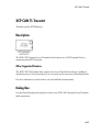
XCP Communication Workflows
XCP Database and Communication Workflow . . . . . . . . . . . .
6-2
vii
7
8
9
A2L File
A2L File Support . . . . . . . . . . . . . . . . . . . . . . . . . . . . . . . . . . . .
7-2
Access an A2L File . . . . . . . . . . . . . . . . . . . . . . . . . . . . . . . . . .
7-3
Access Event Information . . . . . . . . . . . . . . . . . . . . . . . . . . . . .
7-4
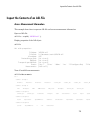
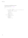
Inspect the Contents of an A2L File . . . . . . . . . . . . . . . . . . . .
Access Measurement Information . . . . . . . . . . . . . . . . . . . . .
7-5
7-5
Universal Measurement & Calibration Protocol
(XCP)
XCP Interface . . . . . . . . . . . . . . . . . . . . . . . . . . . . . . . . . . . . . . .
8-2
XCP Hardware Connection . . . . . . . . . . . . . . . . . . . . . . . . . . .
Create XCP Channel Using CAN Device . . . . . . . . . . . . . . . .
Configure the Channel to Unlock the Slave . . . . . . . . . . . . . .
8-3
8-5
8-6
Read a Single Value . . . . . . . . . . . . . . . . . . . . . . . . . . . . . . . . .
8-7
Write a Single Value . . . . . . . . . . . . . . . . . . . . . . . . . . . . . . . . .
8-8
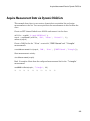
Acquire Measurement Data via Dynamic DAQ Lists . . . . . . .
8-9
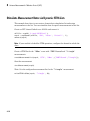
Stimulate Measurement Data via Dynamic STIM Lists . . . .
8-10
CAN Communications in Simulink
Vehicle Network Toolbox Simulink Blocks . . . . . . . . . . . . . .
viii
Contents
9-2
10
CAN Communication in Simulink . . . . . . . . . . . . . . . . . . . . . .
Message Transmission Workflow . . . . . . . . . . . . . . . . . . . . . .
Message Reception Workflow . . . . . . . . . . . . . . . . . . . . . . . .
9-3
9-4
9-6
Open the Vehicle Network Toolbox Block Library . . . . . . . .
Using the MATLAB Command Window . . . . . . . . . . . . . . . .
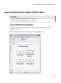
Using the Simulink Library Browser . . . . . . . . . . . . . . . . . .
9-8
9-8
9-9
Build CAN Communication Simulink Models . . . . . . . . . . .
Build a Message Transmit Model . . . . . . . . . . . . . . . . . . . .
Build a Message Receive Model . . . . . . . . . . . . . . . . . . . . . .
Save and Run the Model . . . . . . . . . . . . . . . . . . . . . . . . . . .
9-11
9-11
9-15
9-23
Create Custom Blocks . . . . . . . . . . . . . . . . . . . . . . . . . . . . . . .
9-27
Hardware Limitations
Hardware Limitations By Vendor . . . . . . . . . . . . . . . . . . . . .
Vector Hardware . . . . . . . . . . . . . . . . . . . . . . . . . . . . . . . . .
11
10-2
10-2
XCP Communications in Simulink
Vehicle Network Toolbox XCP Simulink Blocks . . . . . . . . .
11-2
Open the Vehicle Network Toolbox XCP Block Library . . .
Using the MATLAB Command Window . . . . . . . . . . . . . . .
Using the Simulink Library Browser . . . . . . . . . . . . . . . . .
11-3
11-3
11-4
XCP Data Acquisition over CAN . . . . . . . . . . . . . . . . . . . . . .
11-5
ix
12
13
14
x
Contents
Functions — Alphabetical List
Properties — Alphabetical List
Block Reference
1
Getting Started
• “Vehicle Network Toolbox Product Description” on page 1-2
• “Product Capabilities” on page 1-3
• “Install Required Components” on page 1-7
• “Vehicle Network Communication in MATLAB” on page 1-13
• “Vehicle Network Communication Examples” on page 1-16
• “Access the Toolbox” on page 1-31
1
Getting Started
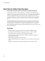
Vehicle Network Toolbox Product Description
Communicate with in-vehicle networks and access ECUs using CAN and XCP protocols
Vehicle Network Toolbox provides connectivity to CAN devices from MATLAB® and
Simulink® using industry-standard CAN database files. The toolbox provides MATLAB
functions and Simulink blocks to send, receive, encode, and decode CAN and XCP
messages, enabling you to exchange messages between a CAN bus and your programs
and models. You also can connect to an ECU via XCP on CAN using A2L description
files.
From MATLAB or Simulink, you can monitor, filter, and analyze live CAN bus data
or log and record CAN messages for later analysis and replay. You also can simulate
message traffic on a virtual CAN bus or connect Simulink models to a live network or
ECU. Vehicle Network Toolbox supports CAN interface devices from Vector, Kvaser, and
National Instruments®.
Key Features
• MATLAB functions for transmitting and receiving CAN and XCP messages
• Simulink CAN and XCP blocks for connecting a model to a CAN bus or ECU
• Vector CAN database (.dbc) file and A2L description file support
• Signal packing and unpacking functions and blocks for simplified encoding and
decoding of CAN messages
• Message filtering, logging, and replay functions
• Vehicle CAN Bus Monitor app to configure devices and visualize live CAN network
traffic
• Support for Vector, Kvaser, and National Instruments CAN interface devices
1-2
Product Capabilities
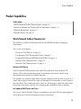
Product Capabilities
In this section...
“Vehicle Network Toolbox Characteristics” on page 1-3
“Interaction Between the Toolbox and Its Components” on page 1-4
“Expected Background ” on page 1-6
“Related Products” on page 1-6
Vehicle Network Toolbox Characteristics
The toolbox is a collection of functions built on the MATLAB technical computing
environment.
You can use the toolbox to:
• “Connect to CAN Devices” on page 1-3
• “Use Supported CAN Devices and Drivers” on page 1-3
• “Communicate Between MATLAB and CAN Bus” on page 1-4
• “Simulate CAN Communication” on page 1-4
• “Visualize CAN Communication” on page 1-4
Connect to CAN Devices
Vehicle Network Toolbox provides host-side CAN connectivity using defined CAN
devices. CAN is the predominant protocol in automotive electronics by which many
distributed control systems in a vehicle function.
For example, in a common design when you press a button to lock the doors in your car, a
control unit in the door reads that input and transmits lock commands to control units in
the other doors. These commands exist as data in CAN messages, which the control units
in the other doors receive and act on by triggering their individual locks in response.
Use Supported CAN Devices and Drivers
You can use Vehicle Network Toolbox to communicate over the CAN bus using supported
Vector, Kvaser, or National Instruments devices and drivers.
1-3
1
Getting Started
See “Supported Hardware” on page 1-10 for more information.
Communicate Between MATLAB and CAN Bus
Using a set of well-defined functions, you can transfer messages between the MATLAB
workspace and a CAN bus using a CAN device. You can run test applications that can log
and record CAN messages for you to process and analyze. You can also replay recorded
sequences of messages.
Simulate CAN Communication
With Vehicle Network Toolbox block library and other blocks from the Simulink library,
you can create sophisticated models to connect to a live network and to simulate message
traffic on a CAN bus.
Visualize CAN Communication
Using Vehicle CAN Bus Monitor, a simple graphical user interface, you can monitor
message traffic on a selected device and channel. You can then analyze these messages.
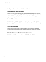
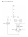
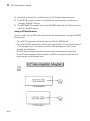
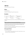
Interaction Between the Toolbox and Its Components
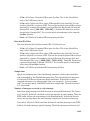
Vehicle Network Toolbox is a conduit between MATLAB and the CAN bus.
1-4
Product Capabilities
In this illustration:
• Six CAN modules are attached to a CAN bus.
• One module, which is a CAN device, is attached to the Vehicle Network Toolbox, built
on the MATLAB technical computing environment.
Using Vehicle Network Toolbox from MATLAB, you can configure a channel on the CAN
device to:
• Transmit messages to the CAN bus.
• Receive messages from the CAN bus.
• Trigger a callback function to run when the channel receives a message.
1-5
1
Getting Started
• Attach the database to the configured CAN channel to interpret received CAN
messages.
• Use the CAN database to construct messages to transmit.
• Log and record messages and analyze them in MATLAB.
• Replay live recorded sequence of messages in MATLAB.
• Build Simulink models to connect to a CAN bus and to simulate message traffic.
• “Monitor Vehicle CAN Bus” with the CAN Tool.
Vehicle Network Toolbox is a comprehensive solution for CAN connectivity in MATLAB
and Simulink. Refer to the Functions and Simulink Blocks for more information.
Expected Background
This document assumes that you are familiar with these products:
• MATLAB — To write scripts and functions, and to use functions with the commandline interface.
• Simulink — To create simple models to connect to a CAN bus or to simulate those
models.
• Vector CANdb — To understand CAN databases and message and signal definitions.
Related Products
MathWorks provides several products that are relevant to the kinds of tasks you can
perform with Vehicle Network Toolbox software and that extend the capabilities of
MATLAB. For information about these related products, see the toolbox product page on
the MathWorks Web site.
1-6
Install Required Components
Install Required Components
In this section...
“Required Components” on page 1-7
“Install Devices and Drivers” on page 1-7
“Install the Toolbox” on page 1-10
“Supported Hardware” on page 1-10
Required Components
To communicate on CAN networks from the MATLAB workspace and using Simulink
models, install these components:
• Current MATLAB version
• Current Vehicle Network Toolbox software
• Hardware, drivers, and driver libraries for your devices
Note: To use the Vehicle Network Toolbox block library, install the current Simulink
version.
Install Devices and Drivers
• “Vector Hardware Devices and Drivers” on page 1-7
• “Kvaser Hardware Devices and Drivers” on page 1-8
• “National Instruments Devices and Drivers” on page 1-8
• “PEAK-System Devices and Drivers” on page 1-9
Vector Hardware Devices and Drivers
You need the latest version of the driver for your device to use with Windows® XP,
Windows Vista™, or Windows 7.
The documentation from Vector provides installation instructions for hardware devices
such as CANcaseXL, CANboardXL, and CANcardXL, drivers, and support libraries.
1-7
1
Getting Started
These drivers are available for download from the Vector Web site at:
http://vector.com/vi_downloadcenter_en.html
Drivers for 32-bit and 64-bit Windows are available in separate packages. Download and
install the latest version and select the appropriate check box during installation for the
hardware you want to use. Virtual channels are also installed with the hardware drivers.
XL Driver Library
Download and install the latest version of the XL Driver Library from the Vector Web
site. A single package contains the driver library for 32-bit and 64-bit Windows. After
installing the library:
• If you have a 32-bit system, copy the file vxlapi.dll from the installation folder to
the windows root\system32 folder.
• If you have a 64-bit system, copy the file vxlapi64.dll from the installation folder
to the windows root\system32 folder.
• If you have a 64-bit system and need to run the 32-bit version of Vehicle Network
Toolbox software, copy the file vxlapi.dll from the installation folder to the
windows root\syswow64 folder.
Kvaser Hardware Devices and Drivers
You need the latest version of the driver for your device to use with Windows XP,
Windows Vista, or Windows 7. Refer to your Kvaser device documentation for hardware
installation instructions.
Drivers for your Kvaser devices are available on the Kvaser Web site at:
http://www.kvaser.com/support/downloads/.
Drivers for 32-bit and 64-bit Windows are available in the same package. Virtual
channels are also installed with the hardware drivers.
National Instruments Devices and Drivers
You need the latest version of the driver for your device to use with Windows XP,
Windows Vista, or Windows 7. Refer to your National Instruments device documentation
for hardware installation instructions.
1-8
Install Required Components
If you are using an NI-CAN device, install the NI-CAN programming library from the
National Instruments Web site. This installs both the drivers and the driver libraries.
If you are using an NI-XNET device, install the latest NI-XNET drivers from the
National Instruments Web site. This installs both the drivers and the driver libraries.
Drivers for 32-bit and 64-bit Windows are available in the same package. Virtual
channels for NI-CAN devices are also installed with the hardware drivers.
Notes You can use National Instruments on a 32-bit system or on 32-bit MATLAB
installed on a 64-bit system.
If you are using National Instruments CompactDAQ devices, you might need to install
additional drivers. Check your device documentation for more information.
Tip To use NI-CAN and NI-XNET on the same system together, assign unique names to
the device channels in NI-MAX before you create channels in the toolbox.
PEAK-System Devices and Drivers
You can use PCAN-USB, PCAN-USB PRO, PCAN-ExpressCard, PCAN-PCI, and PCANPCI Express devices with Vehicle Network Toolbox. You need to download the latest
drivers for your device from the PEAK-System Downloads page.
If your driver installation requires the Microsoft® .NET Framework, the installer will
prompt you and automatically download and install the necessary components.
Driver Library
A single package contains the driver and interface library for 32-bit and 64-bit Windows.
After installing the library:
• If you have a 32-bit system, copy the file PCANBasic.dll from the download folder \
\Disk\PCAN-Basic API\Win32 location to the windows root\system32 folder.
• If you have a 64-bit system, copy the file PCANBasic.dll from the download folder \
\Disk\PCAN-Basic API\Win64 location to the windows root\system32 folder.
• If you have a 64-bit system and need to run the 32-bit version of Vehicle Network
Toolbox software, copy the file PCANBasic.dll from the download folder \\Disk
\PCAN-Basic API\Win64 location to the windows root\syswow64 folder.
1-9
1
Getting Started
Install the Toolbox
Determine if Vehicle Network Toolbox software is installed on your system by typing the
following in the MATLAB Command Window:
ver
The Command Window displays information about the MATLAB version you are
running, including a list of installed add-on products and their version numbers. Check
the list to see if the Vehicle Network Toolbox name appears.
For information about installing the toolbox, refer to the installation documentation for
your platform. If you experience installation difficulties, look for the installation and
license information at the MathWorks Web site:
http://www.mathworks.com/support
Supported Hardware
Vehicle Network Toolbox supports Vector, Kvaser, National Instruments, and PEAKSystem CAN devices.
Supported Vector Devices
Support for Vector CAN devices, including these product families:
• CANcaseXL
• CANcaseXLe
• CANboardXL
• CANboardXL pxi
• CANboardXL PCIe
• CANcardXL
• CANcardX
You can also use the toolbox with virtual CAN channels available with Vector hardware
drivers.
Supported Kvaser Devices
Support for Kvaser CAN devices, including these product families:
1-10
Install Required Components
• WLAN
• PCMCIA
• Leaf
• Memorator
• PCI
• USB
You can also use the toolbox with virtual CAN channels available with Kvaser hardware
drivers.
For a full list of devices, see the Supported Hardware page.
Supported National Instruments Devices
You can use NI-CAN and NI-XNET devices with Vehicle Network Toolbox.
For a complete list of supported NI-CAN devices, see the Supported Hardware page.
All product families of NI-XNET devices are supported including:
• NI 9861, USB-986
• NI 9862, USB-9862
• NI PXI-8513/2, PXI-8513
• NI PXI-8512/2, PXI-8512
• NI PXI-8511/2, PXI-8511
• NI PCI-8513/2, PCI-8513
• NI PCI-8512/2, PCI-8512
• NI PCI-8511/2, PCI-8511
Supported PEAK-System Devices
Support for PEAK-System devices, including these product families:
• PCAN-USB
• PCAN-USB Pro
• PCAN-USB Hub
• PCAN-PC Card
1-11
1
Getting Started
• PCAN-ExpressCard
• PCAN-PCI
• PCAN-PCI Express
• PCAN-cPCI
• PCAN-miniPCI
• PCAN-minPCIe
1-12
Vehicle Network Communication in MATLAB
Vehicle Network Communication in MATLAB
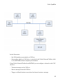
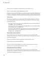
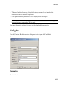
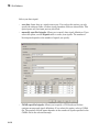
Workflows in this section are sequential and will help you understand how the
communication works. You can also see code snippets and map them to the examples in
the next section.
1-13
1
Getting Started
Transmit Workflow
1-14
Vehicle Network Communication in MATLAB
Receive Workflow
1-15
1
Getting Started
Vehicle Network Communication Examples
In this section...
“Prerequisites” on page 1-16
“Discover Installed Hardware” on page 1-17
“Create a CAN Channel” on page 1-17
“Configure Properties” on page 1-18
“Start the Channel” on page 1-19
“Create a Message” on page 1-19
“Pack a Message” on page 1-20
“Transmit a Message” on page 1-21
“Receive a Message” on page 1-22
“Unpack a Message” on page 1-23
“Save a CAN Channel” on page 1-24
“Load a Saved Channel” on page 1-24
“Filter Messages” on page 1-24
“Multiplex Signals” on page 1-25
“Configure Silent Mode” on page 1-28
“Disconnect Channels and Clean Up” on page 1-28
Prerequisites
Examples follow a sequential workflow for configuring CAN communications. Use these
examples sequentially MATLAB Command Window.
In the example, create two CAN channels using canChannel, and canHWInfo to obtain
information about the devices installed on your system. Edit the properties of the first
channel and create a message using canMessage. Transmit the message from the first
channel using transmit, and receive it on the other using receive .
Before you follow this example, make sure you:
• Complete your toolbox installation before you try out the examples.
• Connect the two channels in your CAN device with a loopback connector.
1-16
Vehicle Network Communication Examples
The following examples use the Vector CANcaseXL hardware. You can substitute it with
any other supported hardware.
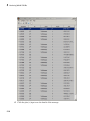
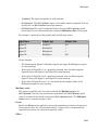
Discover Installed Hardware
1
Get information about the CAN hardware devices on your system:
info = canHWInfo
MATLAB displays the following information:
CAN Devices Detected
Vendor
-----Kvaser
Kvaser
NI
NI
NI
NI
Vector
Vector
Vector
Vector
|
|
|
|
|
|
|
|
|
|
|
|
Device
--------------------------Virtual 1
Virtual 1
Virtual (CAN256)
Virtual (CAN257)
Series 847X Sync USB (CAN0)
Series 847X Sync USB (CAN1)
CANcaseXL 1
CANcaseXL 1
Virtual 1
Virtual 1
|
|
|
|
|
|
|
|
|
|
|
|
Channel
------1
2
1
2
1
1
1
2
1
2
|
|
|
|
|
|
|
|
|
|
|
|
Serial Number
------------0
0
0
0
14E1B6E
14E1B68
24365
24365
0
0
|
|
|
|
|
|
|
|
|
|
|
|
Constructor
------------------------------------canChannel('Kvaser', 'Virtual 1', 1)
canChannel('Kvaser', 'Virtual 1', 2)
canChannel('NI', 'CAN256')
canChannel('NI', 'CAN257')
canChannel('NI', 'CAN0')
canChannel('NI', 'CAN1')
canChannel('Vector', 'CANcaseXL 1', 1)
canChannel('Vector', 'CANcaseXL 1', 2)
canChannel('Vector', 'Virtual 1', 1)
canChannel('Vector', 'Virtual 1', 2)
Use GET on the output of CANHWINFO for more information.
2
Save the vector device information to a variable.
vector = info.VendorInfo(1)
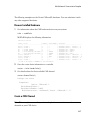
3
Get details about the first available CAN channel.
vector.ChannelInfo(1)
Package: can.vector
Properties:
Device:
DeviceChannelIndex:
DeviceSerialNumber:
ObjectConstructor:
'CANcaseXL 1'
1
24365
'canChannel('Vector','CANcaseXL 1',1)'
Create a CAN Channel
Note: This example assumes that you have a loopback connection between the two
channels on your CAN device.
1-17
1
Getting Started
1
Create the first CAN channel on an installed CAN device:
canch1 = canChannel('Vector','CANcaseXL 1',1)
Notes You cannot use the same variable to create multiple channels sequentially.
Clear any channel in use before using the same variable to construct a new CAN
Channel.
You cannot create arrays of CAN channel objects. Each object you create must
exist as its own individual variable.
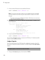
2
Press Enter after you create the connection. MATLAB displays a summary of the
channel properties:
Summary of CAN Channel using 'Vector' 'CANcaseXL 1' Channel 1.
Channel Parameters:
Status:
Filter History:
3
Bus Speed is 500000.
Bus Status is 'N/A'.
Transceiver name is 'CANpiggy 251mag (Highspeed)'.
Serial Number of this device is 24811.
Initialization access is allowed.
No database is attached.
Offline - Waiting for START.
0 messages available to RECEIVE.
0 messages transmitted since last start.
0 messages received since last start.
Standard ID Filter: Allow All | Extended ID Filter: Allow All.
Create a second CAN channel object.
canch2 = canChannel('Vector','CANcaseXL 1',2)
You used the canChannel function to connect to the CAN device. To identify installed
devices, use the canHWInfo function.
Configure Properties
You can set the behavior of your CAN channel by configuring its property values. For
this exercise, change the bus speed of channel 1 to 250000 using the configBusSpeed
function.
Tip Configure property values before you start the channel.
1
1-18
Change the BusSpeed property of the channel to 250000:
Vehicle Network Communication Examples
configBusSpeed(canch1, 250000)
2
To see the changed property value, type:
canch1.BusSpeed
MATLAB displays all properties on the configured channel as before, with the
changed BusSpeed property value:
.
.
.
BusSpeed = 250000
3
Change the bus speed of the second channel (canch2) by repeating steps 2 and 3.
Start the Channel
Start your CAN channels after you configure all properties.
1
Start the first channel:
start(canch1)
2
Start the second channel:
start(canch2)
3
To check that the channel is online, type the channel name in the Command
Window. The Status section indicates that the channel is now online, as in this
example:
>> canch1
.
.
.
Status:
Filter History:
Online.
0 messages available to RECEIVE.
0 messages transmitted since last start.
0 messages received since last start.
Standard ID Filter: Allow All | Extended ID Filter: Allow All.
Create a Message
After you set all the property values as desired and your channels are online, you are
ready to transmit and receive messages on the CAN bus. For this exercise, transmit
1-19
1
Getting Started
a message using canch and receive it using canch1. To transmit a message, create a
message object and pack the message with the required data.
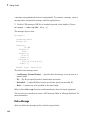
1
Build a CAN message of ID 500 of standard type and a data length of 8 bytes:
messageout = canMessage(500, false, 8)
The message object is now:
messageout =
can.Message handle
Package: can
Properties:
ID:
Extended:
Name:
Database:
Error:
Remote:
Timestamp:
Data:
Signals:
500
0
''
[]
0
0
0
[0 0 0 0 0 0 0 0]
[]
Methods, Events, Superclasses
The fields in the message show:
• can.Message (Normal Frame) — Specifies that the message is not an error or a
remote frame.
• ID — The ID you specified and its hexadecimal equivalent.
• Extended — A logical 0 (false) because you did not specify an extended ID.
• Data — A uint8 array of 0s specified by the data length.
Refer to the canMessage function to understand more about the input arguments.
You can also use a database to create a CAN message. Refer to “Message Database” for
more information.
Pack a Message
After you define the message, pack it with the required data.
1-20
Vehicle Network Communication Examples
1
Use the pack function to pack your message with these input parameters:
pack(messageout, 25, 0, 16, 'LittleEndian')
Here you are specifying the data value to be 25, the start bit to be 0, the signal size
to be 16, and the byte order to be little-endian format.
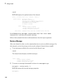
2
To see the packed data, type:
messageout
MATLAB displays your message properties with the specified data:
messageout =
can.Message handle
Package: can
Properties:
ID:
Extended:
Name:
Database:
Error:
Remote:
Timestamp:
Data:
Signals:
500
0
''
[]
0
0
0
[25 0 0 0 0 0 0 0]
[]
Methods, Events, Superclasses
The only field that changes after you specify the data is Data. Refer to the pack function
to understand more about the input arguments.
Transmit a Message
After you define the message and pack it with the required data, you are ready to
transmit the message. For this example, use canch to transmit the message.
1
Use the transmit function to transmit the message, supplying the channel and the
message as input arguments:
transmit(canch1, messageout)
2
To display the channel status, type:
1-21
1
Getting Started
canch1
MATLAB displays the updated status of the channel:
Summary of CAN Channel using 'Vector' 'CANcaseXL 1' Channel 1.
Channel Parameters:
Status:
Filter History:
Bus Speed is 250000.
Bus Status is 'ErrorPassive'.
Transceiver name is 'CANpiggy 251mag (Highspeed)'.
Serial Number of this device is 24811.
Initialization access is allowed.
No database is attached.
Online.
1 messages available to RECEIVE.
1 messages transmitted since last start.
0 messages received since last start.
Standard ID Filter: Allow All | Extended ID Filter: Allow All.
In the Status section, messages transmitted since last start count
increments by 1 each time you transmit a message.
Refer to the transmit function to understand more about the input arguments.
Receive a Message
After your channel is online, use the receive function to receive available messages. For
this example, receive the message on the second configured channel object, canch2.
1
To see messages available to be received on this channel, type:
canch2
The channel status displays available messages:
.
.
.
Status:
2
Online.
1 messages available to RECEIVE.
0 messages transmitted since last start.
0 messages received since last start.
To receive one message from canch1 and store it as messagein, type:
messagein = receive(canch2, 1)
MATLAB returns the received message properties:
messagein =
1-22
Vehicle Network Communication Examples
can.Message handle
Package: can
Properties:
ID:
Extended:
Name:
Database:
Error:
Remote:
Timestamp:
Data:
Signals:
500
0
''
[]
0
0
709.0403
[25 0 0 0 0 0 0 0]
[]
Methods, Events, Superclasses
3
To check if the channel received the message, type:
canch2
MATLAB returns the channel properties, and the status indicates that the channel
received one message:
.
.
.
Status:
Online.
0 messages available to RECEIVE.
0 messages transmitted since last start.
1 messages received since last start.
Refer to the receive function to understand more about its input arguments.
Unpack a Message
After your channel receives a message, specify how to unpack the message and interpret
the data in the message. Use unpack to specify the parameters for unpacking a message:
value = unpack(messagein, 0, 16, 'LittleEndian', 'int16')
The unpacked message returns a value based on your parameters:
value =
1-23
1
Getting Started
25
Refer to the unpack function to understand more about its input arguments.
Save a CAN Channel
You can save a CAN channel object to a file using the save function anytime during the
CAN communication session.
For example, create a channel object canch1. To save it to the MATLAB file
mycanch.mat, type:
save mycanch.mat canch1
Load a Saved Channel
If you have saved a CAN channel as a MATLAB file, you can load it into a session using
the load function. For example, to reload mycanch.mat created above, type:
load mycanch.mat
The loaded CAN channel object reconnects to the specified hardware and reconfigures
itself to the specifications when the channel was saved.
Filter Messages
You can set up filters on your channel to accept messages based on the filtering
parameters you specify. Set up your filters before putting your channel online. For more
information on message filtering, see these functions:
• filterAllowAll
• filterBlockAll
• filterAllowOnly
To specify message names you want to filter, create a CAN channel and attach a
database to the channel:
canch1 = canChannel('Vector','CANcaseXL 1',1);
canch1.Database = canDatabase('demoVNT_CANdbFiles.dbc');
1-24
Vehicle Network Communication Examples
Set a filter for the message EngineMsg and display the channel:
filterAllowOnly(canch1, 'EngineMsg');
canch1
Summary of CAN Channel using 'Vector' 'CANcaseXL 1' Channel 1.
Channel Parameters:
Status:
Filter History:
Bus Speed is 500000.
Bus Status is 'N/A'.
Transceiver name is ''.
Serial Number of this device is 0.
Initialization access is allowed.
'demoVNT_CANdbFiles.dbc' database is attached.
Offline - Waiting for start.
0 messages available to receive.
0 messages transmitted since last start.
0 messages received since last start.
Standard ID Filter: Allow Only | Extended ID Filter: Allow All
If you start the channel and receive messages, you should now only see the EngineMsg
pass through the filter.
Multiplex Signals
Use multiplexing to represent multiple signals in one signal's location in a CAN
message's data. A multiplexed message can have three types of signals:
Standard signal
This signal is always active. You can create one or more standard signals.
Multiplexor signal
Also called the mode signal, it is always active and its value determines which
multiplexed signal is currently active in the message data. You can create only one
multiplexor signal per message.
Multiplexed signal
This signal is active when its multiplex value matches the value of the multiplexor
signal. You can create one or more multiplexed signals in a message.
Multiplexing works only with a CAN database with message definitions that already
contain multiplex signal information. This example shows you how to access the different
multiplex signals using a database constructed specifically for this purpose. This
database has one message with these signals:
• SigA: A multiplexed signal with a multiplex value of 0.
1-25
1
Getting Started
• SigB: Another multiplexed signal with a multiplex value of 1.
• MuxSig: A multiplexor signal, whose value determines which of the two multiplexed
signals are active in the message.
1
Create a CAN database:
d = canDatabase('Mux.dbc')
Note: This is an example database constructed for creating multiplex messages. To
try this example, use your own database.
2
Create a CAN message:
m = canMessage(d, 'Msg')
The message displays all its properties:
m =
can.Message handle
Package: can
Properties:
ID:
Extended:
Name:
Database:
Error:
Remote:
Timestamp:
Data:
Signals:
250
0
'Msg'
[1x1 can.Database]
0
0
0
[0 0 0 0 0 0 0 0]
[1x1 struct]
Methods, Events, Superclasses
3
To display the signals, type:
m.Signals
ans =
SigB: 0
SigA: 0
MuxSig: 0
1-26
Vehicle Network Communication Examples
MuxSig is the multiplexor signal, whose value determines which of the two
multiplexed signals are active in the message. SigA and SigB are the multiplexed
signals that are active in the message if their multiplex values match MuxSig. In the
example shown, SigA is active because its current multiplex value of 0 matches the
value of MuxSig (which is 0).
4
If you want to make SigB active, change the value of the MuxSig to 1:
m.Signals.MuxSig = 1
To display the signals, type:
m.Signals
ans =
SigB: 0
SigA: 0
MuxSig: 1
SigB is now active because its multiplex value of 1 matches the current value of
MuxSig (which is 1).
5
Change the value of MuxSig to 2:
m.Signals.MuxSig = 2
Here, neither of the multiplexed signals are active because the current value of
MuxSig does not match the multiplex value of either SigA or SigB.
m.Signals
ans =
SigB: 0
SigA: 0
MuxSig: 2
Always check the value of the multiplexor signal before using a multiplexed signal
value.
if (m.Signals.MuxSig == 0)
% Feel free to use the value of SigA however is required.
end
1-27
1
Getting Started
This ensures that you are not using an invalid value because the toolbox does not
prevent or protect reading or writing inactive multiplexed signals.
Note: You can access both active and inactive multiplexed signals regardless of the value
of the multiplexor signal.
Refer to the canMessage function to learn more about creating messages.
Configure Silent Mode
The SilentMode property of a CAN channel specifies that the channel can only receive
messages and not transmit them. Use this property to observe all message activity on
the network and perform analysis without affecting the network state or behavior. See
SilentMode for more information.
1
Change the SilentMode property of the first CAN channel, canch1 to true:
canch.SilentMode = true
2
To see the changed property value, type:
canch1.SilentMode
MATLAB displays the changed SilentMode property value:
ans =
1
Disconnect Channels and Clean Up
• “Disconnecting the Configured Channel” on page 1-28
• “Clean Up the MATLAB Workspace” on page 1-29
Disconnecting the Configured Channel
When you no longer need to communicate with your CAN bus, disconnect the CAN
channel that you configured. Use the stop function to disconnect.
1
1-28
Stop the first channel:
Vehicle Network Communication Examples
stop(canch1)
2
Check the channel status:
canch1
MATLAB displays the channel status:
.
.
.
Status:
3
Offline - Waiting for START.
1 messages available to RECEIVE.
1 messages transmitted since last start.
0 messages received since last start.
Stop the second channel:
stop(canch2)
4
Check the channel status:
canch2
MATLAB displays the channel status:
Status:
Offline - Waiting for START.
0 messages available to RECEIVE.
0 messages transmitted since last start.
1 messages received since last start.
Clean Up the MATLAB Workspace
When you no longer need the objects you used, remove them from the MATLAB
workspace. To remove channel objects and other variables from the MATLAB workspace,
use the clear function.
1
Clear the first channel:
clear canch1
2
Clear the second channel:
clear canch2
3
Clear the CAN messages:
clear 'messageout'
clear 'messagein'
4
Clear the unpacked value:
1-29
1
Getting Started
clear value
1-30
Access the Toolbox
Access the Toolbox
In this section...
“Explore the Toolbox” on page 1-31
“Get Help” on page 1-31
“View Examples” on page 1-31
Explore the Toolbox
You can access Vehicle Network Toolbox from the MATLAB Command Window directly
by using any Vehicle Network Toolbox function. To see a list of all the functions
available, type:
help vnt
Get Help
The toolbox functions are grouped by usage. Click a specific function for more
information.
To access the online documentation for the Vehicle Network Toolbox, type:
doc vnt
To access the reference page for a specific function, type:
doc function_name
View Examples
To follow examples in this guide use the Vector CANcaseXL device, with the Vector XL
Driver Library version 6.4 or later. The Examples index in the Help browser lists these
examples.
1-31
2
Hardware Support Package
Installation
• “Vector CAN Device Support” on page 2-2
• “National Instruments NI-CAN Device Support” on page 2-5
• “National Instruments NI-XNET Device Support” on page 2-8
• “Kvaser CAN Device Support” on page 2-11
• “PEAK-System CAN Device Support” on page 2-13
2
Hardware Support Package Installation
Vector CAN Device Support
Use this process to add support for Vector CAN devices to Vehicle Network Toolbox. After
you download and install the Vector driver on your host computer, you can transmit and
receive CAN messages with your Vector hardware using Vehicle Network Toolbox.
Note: You can use this support package only on a host computer running 32-bit or 64-bit
Windows.
2-2
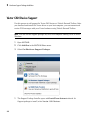
1
Open MATLAB.
2
Click Add-Ons in the MATLAB Home menu.
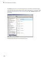
3
Select Get Hardware Support Packages.
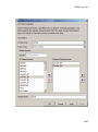
1
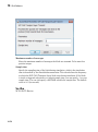
The Support Package Installer opens with Install from Internet selected. At
Support package to install, select Vector CAN Devices.
Vector CAN Device Support
1
Follow the support package installer prompts. When prompted, log into your
MathWorks® account.
Note: You need write privileges for the Installation folder.
2-3
2
Hardware Support Package Installation
At any time during this process, you can click Help for more information about
downloading support packages.
2-4
National Instruments NI-CAN Device Support
National Instruments NI-CAN Device Support
Use this process to add support for NI-CAN devices to Vehicle Network Toolbox. After
you download and install the NI-CAN driver on your host computer, you can transmit
and receive CAN messages on your NI-CAN hardware using Vehicle Network Toolbox.
Note: You can use this support package only on a host computer running 32-bit
Windows.
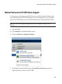
1
Open MATLAB.
2
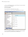
Click Add-Ons in the MATLAB Home menu.
3
Select Get Hardware Support Packages.
1
The Support Package Installer opens with Install from Internet selected. At
Support package to install, select NI-CAN.
2-5
2
Hardware Support Package Installation
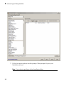
1
Follow the support package installer prompts. When prompted, log into your
MathWorks account.
Note: You need write privileges for the Installation folder.
2-6
National Instruments NI-CAN Device Support
At any time during this process, you can click Help for more information about
downloading support packages.
2-7
2
Hardware Support Package Installation
National Instruments NI-XNET Device Support
Use this process to add support for NI-XNET devices to Vehicle Network Toolbox. After
you download and install the NI-XNET driver on your host computer, you can transmit
and receive CAN messages on your NI-XNET hardware using Vehicle Network Toolbox.
Note: You can use this support package only on a host computer running 32-bit
Windows.
2-8
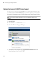
1
Open MATLAB.
2
Click Add-Ons in the MATLAB Home menu.
3
Select Get Hardware Support Packages.
1
The Support Package Installer opens with Install from Internet selected. At
Support package to install, select NI-XNET.
National Instruments NI-XNET Device Support
1
Follow the support package installer prompts. When prompted, log into your
MathWorks account.
Note: You need write privileges for the Installation folder.
2-9
2
Hardware Support Package Installation
At any time during this process, you can click Help for more information about
downloading support packages.
2-10
Kvaser CAN Device Support
Kvaser CAN Device Support
Use this process to add support for Kvaser devices to Vehicle Network Toolbox. After you
download and install the Kvaser driver on your host computer, you can transmit and
receive CAN messages on your Kvaser hardware using Vehicle Network Toolbox.
Note: You can use this support package only on a host computer running 32-bit or 64-bit
Windows.
1
Open MATLAB.
2
Click Add-Ons in the MATLAB Home menu.
3
Select Get Hardware Support Packages.
1
The Support Package Installer opens with Install from Internet selected. At
Support package to install, select Kvaser CAN Devices.
2-11
2
Hardware Support Package Installation
2
Follow the support package installer prompts. When prompted, log into your
MathWorks account.
Note: You need write privileges for the Installation folder.
At any time during this process, you can click Help for more information about
downloading support packages.
2-12
PEAK-System CAN Device Support
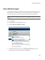
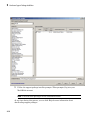
PEAK-System CAN Device Support
Use this process to add support for PEAK-System CAN devices to Vehicle Network
Toolbox. After you download and install the PEAK-System driver on your host computer,
you can transmit and receive CAN messages with your PEAK–System hardware using
Vehicle Network Toolbox.
Note: You can use this support package only on a host computer running 32-bit or 64-bit
Windows.
1
Open MATLAB.
2
Click Add-Ons in the MATLAB Home menu.
3
Select Get Hardware Support Packages.
1
The Support Package Installer opens with Install from Internet selected. At
Support package to install, select PEAK-System CAN Devices.
2-13
2
Hardware Support Package Installation
1
Follow the support package installer prompts. When prompted, log into your
MathWorks account.
Note: You need write privileges for the Installation folder.
2-14
PEAK-System CAN Device Support
At any time during this process, you can click Help for more information about
downloading support packages.
2-15
3
CAN Communication Workflows
• “CAN Transmit Workflow” on page 3-2
• “CAN Receive Workflow” on page 3-5
3
CAN Communication Workflows
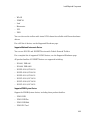
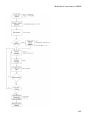
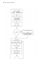
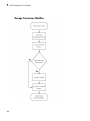
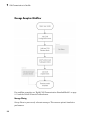
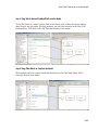
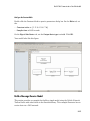
CAN Transmit Workflow
This workflow helps you create a CAN channel and transmit messages.
3-2
CAN Transmit Workflow
3-3
3
CAN Communication Workflows
See Also
Functions
canChannel | canDatabase | canMessage | canMessageImport | configBusSpeed
| pack | start | stop | transmit | transmitConfiguration | transmitEvent |
transmitPeriodic
Properties
Data | Database | Error | Extended | ID | Name (Message) | Remote | Signals
| Timestamp | UserData
Blocks
CAN Pack | CAN Replay | CAN Transmit
3-4
CAN Receive Workflow
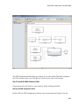
CAN Receive Workflow
Use this workflow to receive and unpack CAN messages.
3-5
3
3-6
CAN Communication Workflows
CAN Receive Workflow
See Also
Functions
attachDatabase | canDatabase | configBusspeed | extractAll |
extractRecent | extractTime | receive | stop | unpack
Properties
MessageReceivedFcn | MessageReceivedFcnCount | MessagesAvailable |
MessagesReceived | MessagesTransmitted
ReceiveErrorCount | TransmitErrorCount
Blocks
CAN Log | CAN Receive | CAN Unpack
3-7
4
Using a CAN Database
• “Vector CAN Database Support” on page 4-2
• “Load .dbc Files and Create Messages” on page 4-3
• “Other Uses of the CAN Database” on page 4-15
4
Using a CAN Database
Vector CAN Database Support
A CAN database contains physical message and signal definitions. Using a CAN
database, you can represent message and signal information in engineering units and do
need not manipulate raw data bytes. You can use a Vector CAN database with Vehicle
Network Toolbox. A .dbc file contains definitions of CAN messages and signals.
Look up message and signal information and build messages using the information
defined in the database file.
4-2
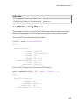
Load .dbc Files and Create Messages
Load .dbc Files and Create Messages
In this section...
“Load the CAN Database” on page 4-3
“Create a CAN Message” on page 4-3
“Access Signals in the Constructed CAN Message” on page 4-4
“Add a Database to a CAN Channel” on page 4-4
“Update Database Information” on page 4-5
“Create and Process Messages Using Database Definitions” on page 4-5
Load the CAN Database
To use a CAN database file, load the database into your MATLAB session. At the
MATLAB command prompt, type:
db = canDatabase('filename.dbc')
Here db is a variable you chose for your database handle and filename.dbc is the
actual file name of your CAN database. If your CAN database is not in the current
working directory, type the path to the database:
db = canDatabase('path\filename.dbc')
Tip CAN database file names containing non-alphanumeric characters such as equal
signs, ampersands, and so forth are incompatible with Vehicle Network Toolbox. You
can use periods in your database name. Rename any CAN database files with nonalphanumeric characters before you use them.
This command returns a database object that you can use to create and interpret CAN
messages using information stored in the database. Refer to the canDatabase function
for more information.
Create a CAN Message
This example shows you how to create a message using a database constructed
specifically for this example. You can access this database in the Toolbox > VNT
4-3
4
Using a CAN Database
> VNTDemos subfolder in your MATLAB installation folder. This database has a
message, EngineMsg. To try this example, create messages and signals using definitions
in your own database.
1
Create the CAN database object:
d = canDatabase('demoVNT_CANdbFiles.dbc')
2
Create a CAN message using the message name in the database:
message = canMessage(d, 'EngineMsg')
Access Signals in the Constructed CAN Message
You can access the two signals defined for the message you created in the example
database, message. You can also change the values for some signals.
1
To display signals in your message, type:
sig = (message.Signals)
Signals in the message are displayed as follows:
sig =
VehicleSpeed: 0
EngineRPM: 250
2
Change the value of the EngineRPM signal:
message.Signals.EngineRPM = 300
3
Display signal information again to see the change:
sig
sig =
VehicleSpeed: 0
EngineRPM: 300
Add a Database to a CAN Channel
To add a database to the CAN channel canch, type:
4-4
Load .dbc Files and Create Messages
canch.Database = canDatabase('Mux.dbc')
For more information, see the Database property.
Update Database Information
When you make changes to a database file:
1
Reload the database file into your MATLAB session using the canDatabase
function.
2
Reattach the database to messages using the attachDatabase function.
Create and Process Messages Using Database Definitions
This example shows you how to create, receive and process messages using
information stored in CAN database files. This example uses the CAN database file,
demoVNT_CANdbFiles.dbc.
Open the Database File
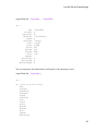
Open the database file and examine the Messages property to see the names of all
message defined in this database.
db = canDatabase('demoVNT_CANdbFiles.dbc')
db.Messages
db =
can.Database handle
Package: can
Properties:
Name:
Path:
Messages:
UserData:
'demoVNT_CANdbFiles'
[1x75 char]
{5x1 cell}
[]
ans =
4-5
4
Using a CAN Database
'DoorControlMsg'
'EngineMsg'
'SunroofControlMsg'
'TransmissionMsg'
'WindowControlMsg'
View Message Information
Use messageInfo to view message information, including the identifier, data length,
and a signal list.
messageInfo(db, 'EngineMsg')
ans =
Name:
Comment:
ID:
Extended:
Length:
Signals:
'EngineMsg'
''
100
0
8
{2x1 cell}
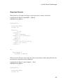
You can also query for information on all messages at once.
messageInfo(db)
ans =
5x1 struct array with fields:
Name
Comment
ID
Extended
Length
Signals
View Signal Information
Use signalInfo to view signal definition information, including type, byte ordering,
size, and scaling values that translate raw signals to physical values.
4-6
Load .dbc Files and Create Messages
signalInfo(db, 'EngineMsg', 'EngineRPM')
ans =
Name:
StartBit:
SignalSize:
ByteOrder:
Signed:
ValueType:
Class:
Factor:
Offset:
Minimum:
Maximum:
Units:
Comment:
Multiplexor:
Multiplexed:
MultiplexMode:
'EngineRPM'
0
32
'LittleEndian'
0
'Integer'
'uint32'
0.1000
250
250
9500
'rpm'
''
0
0
0
You can also query for information on all signals in the message at once.
signalInfo(db, 'EngineMsg')
ans =
2x1 struct array with fields:
Name
StartBit
SignalSize
ByteOrder
Signed
ValueType
Class
Factor
Offset
Minimum
Maximum
Units
Comment
Multiplexor
4-7
4
Using a CAN Database
Multiplexed
MultiplexMode
Create a Message Using Database Definitions
Specify the name of the message when you create a new message to have the database
definition applied. CAN signals in this messages are represented in engineering units in
addition to the raw data bytes.
msgEngineInfo = canMessage(db, 'EngineMsg')
msgEngineInfo =
can.Message handle
Package: can
Properties:
ID:
Extended:
Name:
Database:
Error:
Remote:
Timestamp:
Data:
Signals:
UserData:
100
0
'EngineMsg'
[1x1 can.Database]
0
0
0
[0 0 0 0 0 0 0 0]
[1x1 struct]
[]
View Signal Information
Use the Signals property to see signal values for this message. You can directly write to
and read from these signals to pack or unpack data from the message.
msgEngineInfo.Signals
ans =
VehicleSpeed: 0
EngineRPM: 250
4-8
Load .dbc Files and Create Messages
Change Signal Information
Write directly to the signal to change a value and read its current value back.
msgEngineInfo.Signals.EngineRPM = 5500.25
msgEngineInfo.Signals
msgEngineInfo =
can.Message handle
Package: can
Properties:
ID:
Extended:
Name:
Database:
Error:
Remote:
Timestamp:
Data:
Signals:
UserData:
100
0
'EngineMsg'
[1x1 can.Database]
0
0
0
[23 205 0 0 0 0 0 0]
[1x1 struct]
[]
ans =
VehicleSpeed: 0
EngineRPM: 5.5003e+03
When you write directly to the signal, the value is translated, scaled, and packed into the
message data using the database definition.
msgEngineInfo.Signals.VehicleSpeed = 70.81
msgEngineInfo.Signals
msgEngineInfo =
can.Message handle
Package: can
4-9
4
Using a CAN Database
Properties:
ID:
Extended:
Name:
Database:
Error:
Remote:
Timestamp:
Data:
Signals:
UserData:
100
0
'EngineMsg'
[1x1 can.Database]
0
0
0
[23 205 0 0 71 0 0 0]
[1x1 struct]
[]
ans =
VehicleSpeed: 71
EngineRPM: 5.5003e+03
Receive Messages with Database Information
Attach a database to a CAN channel that receives messages to apply database definitions
to incoming messages automatically. The database decodes only messages that are
defined. All other messages are received in their raw form.
rxCh = canChannel('Vector', 'Virtual 1', 2);
rxCh.Database = db
rxCh =
Summary of CAN Channel using 'Vector' 'Virtual 1' Channel 2.
Channel Parameters:
Status:
4-10
Bus Speed is 500000.
Bus Status is 'N/A'.
Transceiver name is ''.
Serial Number of this device is 0.
Initialization access is allowed.
'demoVNT_CANdbFiles.dbc' database is attached.
Offline - Waiting for start.
0 messages available to receive.
0 messages transmitted since last start.
0 messages received since last start.
Load .dbc Files and Create Messages
Filter History:
Standard ID Filter: Allow All | Extended ID Filter: Allow All
Receive Messages
Start the channel, generate some message traffic and receive messages with physical
message decoding.
start(rxCh);
generateMsgsDb();
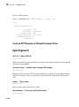
rxMsg = receive(rxCh, Inf)
rxMsg =
1x418 can.Message handle
Package: can
Properties:
ID
Extended
Name
Database
Error
Remote
Timestamp
Data
Signals
UserData
Stop the channel and clear it from the workspace.
stop(rxCh);
clear rxCh
Examine a Received Message
Inspect a received message to see the applied database decoding.
rxMsg(10)
rxMsg(10).Signals
4-11
4
Using a CAN Database
ans =
can.Message handle
Package: can
Properties:
ID:
Extended:
Name:
Database:
Error:
Remote:
Timestamp:
Data:
Signals:
UserData:
100
0
'EngineMsg'
[1x1 can.Database]
0
0
0.1746
[88 134 0 0 52 0 0 0]
[1x1 struct]
[]
ans =
VehicleSpeed: 52
EngineRPM: 3.6892e+03
Extract Most Recent Message by Name
Use extractRecent and specify a message name to extract the most recent occurrence
of a message.
msgRecentWindows = extractRecent(rxMsg, 'WindowControlMsg')
msgRecentWindows =
can.Message handle
Package: can
Properties:
ID:
Extended:
Name:
Database:
Error:
Remote:
4-12
600
0
'WindowControlMsg'
[1x1 can.Database]
0
0
Load .dbc Files and Create Messages
Timestamp:
Data:
Signals:
UserData:
5.5749
[64 62 0 0]
[1x1 struct]
[]
Extract All Instances of a Specified Message by Name
Use extractAll and specify a message name to extract all instances of a specified
message.
allMsgEngine = extractAll(rxMsg, 'EngineMsg')
allMsgEngine =
1x225 can.Message handle
Package: can
Properties:
ID
Extended
Name
Database
Error
Remote
Timestamp
Data
Signals
UserData
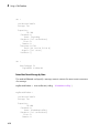
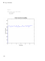
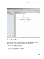
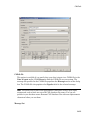
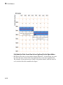
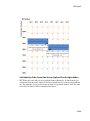
Plot Physical Signal Values
Plot the values of database decoded signals over time. Reference the message timestamps
and the signal values in variables.
signals = [allMsgEngine.Signals]
plot([allMsgEngine.Timestamp], [signals.VehicleSpeed])
title('Vehicle Speed from EngineMsg', 'FontWeight', 'bold')
xlabel('Timestamp')
ylabel('Vehicle Speed')
axis([0 6 0 75])
4-13
4
Using a CAN Database
signals =
1x225 struct array with fields:
VehicleSpeed
EngineRPM
4-14
Other Uses of the CAN Database
Other Uses of the CAN Database
In this section...
“View Message Information in a CAN Database” on page 4-15
“View Signal Information in a CAN Message” on page 4-16
“Attach a CAN Database to Existing Messages” on page 4-16
View Message Information in a CAN Database
You can look up information on message definitions by a single message by name, or a
single message by ID. You can also look up information on all message definitions in the
database by typing:
msgInfo = messageInfo(database name)
This command returns the message structure of information about messages in the
database. For example:
msgInfo =
5x1 struct array with fields:
Name
Comment
ID
Extended
Length
Signals
To get information on a single message by message name, type:
msgInfo = messageInfo(database name, 'message name')
This command returns information about the message as defined in the database. For
example:
msgInfo = messageInfo(db, 'EngineMsg')
msgInfo =
Name: 'EngineMsg'
Comment: ''
4-15
4
Using a CAN Database
ID:
Extended:
Length:
Signals:
100
0
8
{2x1 cell}
Here the function returns information about message with name EngineMsg in the
database db. You can also use the message ID to get information about a message. For
example, to view the example message given here by inputting the message ID, type:
msgInfo = messageInfo(db, 100, false)
This command provides the database name, the message ID, and a Boolean value for the
extended value of the ID.
To learn how to use it and work with the database, see the messageInfo function.
View Signal Information in a CAN Message
You can get signal definition information on a specific signal or all signals in a CAN
message with database definitions attached. Provide the message name or the ID as a
parameter in the command:
sigInfo = signalInfo(db, 'EngineMsg')
You can also get information about a specific signal by providing the signal name:
sigInfo = signalInfo(db, 'EngineMsg', 'EngineRPM')
To learn how to use this property and work with the database, see the signalInfo
function.
You can also access the Signals property of the message to view physical signal
information. When you create physical signals using database information, you can
directly write to and read from these signals to pack or unpack data from the message.
When you write directly to the signal name, the value is translated, scaled, and packed
into the message data.
Attach a CAN Database to Existing Messages
You can attach a .dbc file to messages and apply the message definition defined in the
database. Attaching a database allows you to view the messages in their physical form
and use a signal-based interaction with the message data.
4-16
Other Uses of the CAN Database
To attach a database to a message, type:
attachDatabase(message name, database name)
Note: If your message is an array, all messages in the array are associated with the
database that you attach.
You can also dissociate a message from a database so that you can view the message in
its raw form. To clear the attached database from a message, type:
attachDatabase(message name, [])
Note: The database gets attached even if the database does not find the specified
message. Even though the database is still attached to the message, the message is
displayed in its raw mode.
For more information, see the attachDatabase function.
4-17
5
Monitoring Vehicle CAN Bus
• “Vehicle CAN Bus Monitor” on page 5-2
• “Using the Vehicle CAN Bus Monitor” on page 5-8
5
Monitoring Vehicle CAN Bus
Vehicle CAN Bus Monitor
In this section...
“About the Vehicle CAN Bus Monitor” on page 5-2
“Opening the Vehicle CAN Bus Monitor” on page 5-2
“Vehicle CAN Bus Monitor Fields” on page 5-2
About the Vehicle CAN Bus Monitor
Vehicle Network Toolbox provides a graphical user interface that monitors CAN bus
traffic on selected channels. Using the CAN Bus Monitor you can:
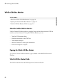
• View live CAN message data.
• Configure connection to the CAN bus.
• View unique messages.
• Attach a database to view signal information.
• Save the messages to a log file.
Opening the Vehicle CAN Bus Monitor
To open the Vehicle CAN Bus Monitor, type canTool in the MATLAB Command
Window.
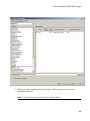
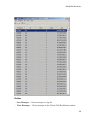
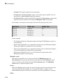
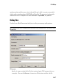
Vehicle CAN Bus Monitor Fields
The CAN bus monitor has the following menus, buttons and table.
5-2
Vehicle CAN Bus Monitor
File Menu
• Save Messages — Saves messages to a log file.
• Clear Messages — Clears messages in the Vehicle CAN Bus Monitor window.
5-3
5
Monitoring Vehicle CAN Bus
• Exit CAN Tool — Click to exit the CAN Tool window.
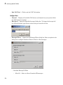
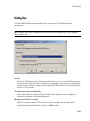
Configure Menu
• Channel — Displays all available CAN devices and channels on your system. Select
the CAN channel to monitor.
• Bus Speed — Opens the Specified bus speed dialog box. To change the bus speed of
the selected channel, type the new value in bits per second in the box.
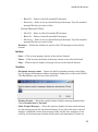
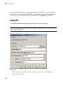
• Message Filters — Opens the Set Message Filters dialog box. Select an option in the
dialog box to configure hardware filters to block or allow messages.
• Standard Message ID Filter
• Allow All — Select to allow all standard ID messages.
5-4
Vehicle CAN Bus Monitor
• Block All — Select to block all standard ID messages.
• Allow only — Select to set up custom filtering of messages. Type the standard
message IDs that you want to allow.
• Extended Message ID Filter
• Allow All — Select to allow all extended ID messages.
• Block All — Select to block all extended ID messages.
• Allow only — Select to set up custom filtering of messages. Type the extended
message IDs that you want to allow.
• Database — Selects the database to attach to the CAN messages on the selected
channel.
Run Menu
• Start — Click to view message activity on the selected channel.
• Pause — Click to pause the display of message activity on the selected channel.
• Stop — Click to stop the display of message activity on the selected channel.
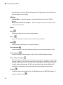
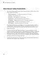
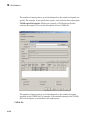
View Menu
• Maximum message count — Opens the Specify maximum message count dialog
box. To change the maximum number of messages displayed at a time in the Vehicle
CAN Bus Monitor, type the new value in the box.
• Number Format — Select the number format to display message identifier data.
Choose Hexadecimal or Decimal.
• Show Unique Messages — Select this option to display the most recent instance
of each message received on the selected channel. If you select this option, the tool
displays a simplified version of the message traffic. In this view, messages do not
scroll up, but each message refreshes its data with each timestamp. If you do not
5-5
5
Monitoring Vehicle CAN Bus
select this option, the tool displays all instances of all messages in the order that the
selected channel receives them.
Help Menu
• canTool Help — Select this option to see the online help for Vehicle CAN Bus
Monitor.
• About Vehicle Network Toolbox — Select this option to view the toolbox version
and release information.
Buttons
Start
Displays message activity on the selected channel.
Pause
Pauses the display of message activity on the selected channel.
Stop
Stops displaying messages on the selected channel.
Save messages
Click this button to save the current message list on the selected channel to a file.
Clear messages
Click this button to clear messages in the Vehicle CAN Bus Monitor window.
Show unique messages
Select this option to display the most recent instance of each message received on the
selected channel. If you select this option, the tool displays a simplified version of the
message traffic. In this view, messages do not scroll up, but each message refreshes
its data with each timestamp. If you do not select this option the tool displays all
instances of all messages in the order that the selected channel receives them.
Docking
Click this button to dock the Vehicle CAN Bus Monitor to the MATLAB desktop. To
undock, click this button
5-6
.
Vehicle CAN Bus Monitor
Undocking
Click this button to undock the Vehicle CAN Bus Monitor from the MATLAB
desktop. To dock, click this button.
Message Table
Timestamp
Displays the time, relative to the start time, that the device receives the message.
The start time begins at 0 when you click Start.
ID
Displays the message ID. This field displays a number in hexadecimal format for the
ID and:
• Displays numbers only for standard IDs.
• Appends an x for an extended ID.
• Displays an r for a remote frame.
• Displays error for messages with error frames.
To change the format to decimal, select View > Number Format > Decimal.
Name
Displays the name of the message, if available.
Length
Displays the length of the message in bytes.
Data
Displays the data in the message in hexadecimal format.
To change the format to decimal, select View > Number Format > Decimal.
If you are using a database, click the + sign to see signal information. The tool displays
the signal name and the physical value of the message, as defined in the attached
database.
5-7
5
Monitoring Vehicle CAN Bus
Using the Vehicle CAN Bus Monitor
In this section...
“View Messages on a Channel” on page 5-8
“Configure the Channel Bus Speed” on page 5-8
“Filter CAN Messages in Vehicle CAN Bus Monitor” on page 5-9
“Attach a Database” on page 5-9
“Change the Message Count” on page 5-11
“Change the Number Format” on page 5-11
“View Unique Messages” on page 5-11
“Save the Message Log File” on page 5-12
View Messages on a Channel
1
Open the Vehicle CAN Bus Monitor and select the device and channel connected to
your CAN bus by selecting Configure > Channel.
2
The Vehicle CAN Bus Monitor defaults to the bus speed set in the device driver. You
can also configure a new bus speed. See Configuring the Channel Bus Speed
3
Click Start, or select Run > Start.
4
To pause the display, click Pause or select Run > Pause.
5
To stop the display, click Stop or select Run > Stop.
Configure the Channel Bus Speed
Configure the bus speed when your network speed differs from the default value of the
channel. You require initialization access for the channel to configure the bus speed.
To configure a new bus speed:
1
Select Configure > Bus Speed.
2
Type the desired value in the Specify bus speed dialog box.
3
Click OK.
The value you set takes effect once you start the CAN channel. If an error occurs when
applying the new bus speed, the value reverts to the default value specified in the
hardware.
5-8
Using the Vehicle CAN Bus Monitor
Filter CAN Messages in Vehicle CAN Bus Monitor
Filter CAN messages to allow or block messages displayed in the Vehicle CAN Bus
Monitor.
To set up filters:
1
Select Configure > Message Filters.
2
To set filters on standard message IDs, select:
3
a
Allow All to set the hardware filter to allow all messages with standard IDs.
b
Block All to set the hardware filter to block all messages with standard IDs.
c
Allow Only to set up custom filters. Type the standard IDs of the message you
want to filter. You can type a range or single IDs. The default is 0:2047.
To set filters on extended message IDs, select:
a
Allow All to set the hardware filter to allow all messages extended IDs.
b
Block All to set the hardware filter to block all messages extended IDs.
c
Allow Only to set up custom filters. Type the extended IDs of the message you
want to filter. You can type a range or single IDs. The default is 0:536870911.
Note: If you are using a custom filter, change the default range to the desired
range. The default range allows all messages and you should select Allow All to
allow all incoming messages with extended IDs.
4
Click OK.
Attach a Database
Attach a database to the Vehicle CAN Bus Monitor to see signal information of the
displayed messages.
1
Select Run > Stop to stop the message display in the Vehicle CAN Bus Monitor.
2
Select Configure > Database.
3
Select the database to attach and start the message display again.
When the tool displays the messages, it shows the message name in the Message
table.
5-9
5
Monitoring Vehicle CAN Bus
4
5-10
Click the plus (+) sign to see the details of the message.
Using the Vehicle CAN Bus Monitor
The tool displays the signal name as defined in the attached database and the signal's
physical value.
Change the Message Count
You can change the maximum number of messages displayed to a value from 100
through 5000.
1
Select View > Maximum Message Count.
2
In the Specify maximum message count dialog box, type the number of messages you
want displayed at one time.
3
Click OK.
Change the Number Format
By default the message data is displayed in hexadecimal format. To change the display to
decimal format, select View > Number Format > Decimal.
View Unique Messages
To view the most recent instance of each unique message received on the channel, select
View > Show Unique Messages. In this view, you do not see messages scroll up, but
each message refreshes its data and timestamp with each new instance. You can also
click
.
5-11
5
Monitoring Vehicle CAN Bus
Use this feature to get a snapshot of message IDs that the selected channel receives. Use
this information to analyze specific messages.
When you select Show Unique Messages, the tool continues to receive message
actively. This simplified view allows you to focus on specific messages and analyze them.
To save messages when Show Unique Messages is selected, click Pause and then click
Save. You cannot save just the unique message list. This operation saves the complete
message log in the window.
Save the Message Log File
You can save a log file of the messages currently displayed while the tool is running. You
need not stop or pause the display to save a log file.
To save a log file of the messages currently displayed in the window, select File > Save
Messages or click
.
The tool saves the messages in a MATLAB file in your current working folder by default.
You can change the location by browsing to a different folder in the Save dialog box.
Each time you save the message log to a file, the Vehicle CAN Bus Monitor saves them as
VNT CAN Log.mat with sequential numbering by default. You can change the name by
typing a new name in Save dialog box.
5-12
6
XCP Communication Workflows
6
XCP Communication Workflows
XCP Database and Communication Workflow
This workflow helps you:
• Manage an A2L database
• Connect to an XCP device
• Create an XCP channel
• Acquire and stimulate data
• Read and write to memory
6-2
XCP Database and Communication Workflow
6-3
6
XCP Communication Workflows
See Also
Functions
connect | createMeasurementList | disconnect | freeMeasurementLists |
getEventInfo | getMeasurementInfo | isConnected | isMeasurementRunning
| readDAQListData | readSingleValue | startMeasurement | stopMeasurement
| viewMeasurementLists | writeSingleValue | writeSTIMListData | xcpA2L |
xcpChannel
Properties
A2LFileName | A2LFileName | DAQInfo | Events | FileName | FilePath
| Measurements | ProtocolLayerInfo | SeedKeyDLL | SeedKeyDLL |
SlaveName | SlaveName | SlaveName | TransportLayer | TransportLayer |
TransportLayerCANInfo | TransportLayerDevice | TransportLayerDevice
Blocks
XCP CAN TL Receive | XCP CAN TL Transmit | XCP CAN Transport Layer | XCP
Configuration | XCP Configuration | XCP Data Acquisition | XCP Data Stimulation
6-4
7
A2L File
• “A2L File Support” on page 7-2
• “Access an A2L File” on page 7-3
• “Access Event Information” on page 7-4
• “Inspect the Contents of an A2L File” on page 7-5
7
A2L File
A2L File Support
An A2L file is a special description file that defines the implementation of an ECU that
can communicate with a slave module via an XCP connection. An A2L file is a formatted
text file that contains event and measurement definitions as well as other configuration
information. You can use this information to connect an XCP channel to a slave module
and acquire and stimulate data and perform other functions.
7-2
Access an A2L File
Access an A2L File
To use a A2L file, open the file in your MATLAB session. At the MATLAB command
prompt, type:
a2lfile = xcpA2L('filename.a2l')
Here a2lfile is a variable you chose for your A2L object and filename.a2l is the
actual file name of your A2L file. If your A2L file is not in the current working directory,
type the path to the file:
a2lfile = xcpA2L('path\filename.a2l');
Tip A2L file names containing non-alphanumeric characters such as equal signs,
ampersands, and so forth are incompatible with Vehicle Network Toolbox. You can use
periods in your database name. Rename any A2L files with non-alphanumeric characters
before you use them.
This command returns a A2L object that you can use with live communication to a slave
module using XCP channels.
7-3
7
A2L File
Access Event Information
This example shows how to open an A2L file and access event information.
Open an A2L file:
a2lfile = xcpA2L('XCPSIM.a2l');
Display properties of the A2L object:
a2lfile
A2L with properties:
FileName:
FilePath:
SlaveName:
ProtocolLayerInfo:
DAQInfo:
TransportLayerCANInfo:
Events:
Measurements:
'XCPSIM.a2l'
'H:\Documents\work\XCPSIM.a2l'
'CPP'
[1x1 struct]
[1x1 struct]
[1x1 struct]
{'Key T' '10 ms' '100ms' '1ms'
{1x38 cell}
'FilterBypassDaq'
'Filte
View all available events:
a2lfile.Events
ans =
'Key T'
'10 ms'
'100ms'
'1ms'
Get information for the 10 ms event:
getEventInfo(a2lfile,'10 ms')
ans =
Name:
Direction:
MaxDAQList:
ChannelNumber:
ChannelTimeCycle:
ChannelTimeUnit:
ChannelPriority:
ChannelTimeCycleInSeconds:
7-4
'10 ms'
'DAQ_STIM'
255
1
10
6
0
0.0100
'FilterBypassDaq'
'FilterBypassSt'
Inspect the Contents of an A2L File
Inspect the Contents of an A2L File
Access Measurement Information
This example shows how to open an A2L file and access measurement information.
Open an A2L file:
a2lfile = xcpA2L('XCPSIM.a2l');
Display properties of the A2L object:
a2lfile
A2L with properties:
FileName:
FilePath:
SlaveName:
ProtocolLayerInfo:
DAQInfo:
TransportLayerCANInfo:
Events:
Measurements:
'XCPSIM.a2l'
'H:\Documents\work\XCPSIM.a2l'
'CPP'
[1x1 struct]
[1x1 struct]
[1x1 struct]
{'Key T' '10 ms' '100ms' '1ms'
{1x38 cell}
'FilterBypassDaq'
'Filte
View all available measurements:
a2lfile.Measurements
ans =
Columns 1 through 8
'BitSlice'
'BitSlice0'
'BitSlice1'
'BitSlice2'
'Counter_B4'
'Counter_B5'
'Counter_B6'
'Counter_B7
Columns 9 through 16
'FW1'
'KL1Output'
'PWM'
'PWMFiltered'
'PWM_Level'
'ShiftByte'
'Shifter_B0'
'Shifter_B1'
Columns 17 through 25
'Shifter_B2'
'Shifter_B3'
'TestStatus'
'Triangle'
'ampl'
'bit12Counter'
'byte1'
'byte2'
'byte3
Columns 26 through 33
'byte4'
'byteCounter'
'bytePWMFilter'
'channel3'
'dwordCounter'
'map1InputX'
'map1InputY'
Columns 34 through 38
'period'
'sbytePWMLevel'
'v'
'vin'
'wordCounter'
7-5
'map1Ou
7
A2L File
Get information about the BitSlice measurement:
getMeasurementInfo(a2lfile,'Triangle')
ans =
Name:
LongIdentifier:
DataType:
Conversion:
Resolution:
Accuracy:
LowerLimit:
UpperLimit:
ECUAddress:
ECUAddressExtension:
ByteOrder:
SizeInBytes:
SizeInNibbles:
SizeInBits:
MATLABType:
7-6
'Triangle'
'Triangle test signal used for PWM output PWM'
'SBYTE'
'BitSlice.CONVERSION'
0
0
-50
50
4951377
0
'MSB_LAST'
1
2
8
'int8'
8
Universal Measurement & Calibration
Protocol (XCP)
• “XCP Interface” on page 8-2
• “XCP Hardware Connection” on page 8-3
• “Read a Single Value” on page 8-7
• “Write a Single Value” on page 8-8
• “Acquire Measurement Data via Dynamic DAQ Lists” on page 8-9
• “Stimulate Measurement Data via Dynamic STIM Lists” on page 8-10
8
Universal Measurement & Calibration Protocol (XCP)
XCP Interface
XCP is a high-level protocol that allows you to acquire, stimulate and calibrate data in
electronic control units (ECU). XCP accesses ECU modules via an interface such as CAN.
The XCP master communicates with one or more slave modules by sending commands.
Using industry standard A2L files, you can read and write to memory or perform data
acquisition and stimulation.
XCP allows you to:
• Perform Data acquisition and stimulation
• Read and write to device memory
• Dynamically configure data acquisition
8-2
XCP Hardware Connection
XCP Hardware Connection
You can connect your XCP master to a slave module using the CAN protocol. This allows
you to use events and access measurements on the slave module.
8-3
8
8-4
Universal Measurement & Calibration Protocol (XCP)
XCP Hardware Connection
In this section...
“Create XCP Channel Using CAN Device” on page 8-5
“Configure the Channel to Unlock the Slave ” on page 8-6
Create XCP Channel Using CAN Device
This example shows how to create an XCP CAN channel connection and access channel
properties. The example also shows how to unlock the slave using seed key security.
Access an A2L file that describe the slave module.
a2lfile = xcpA2L('C:\work\XCPSIM.a2l')
a2lfile =
A2L with properties:
FileName:
FilePath:
SlaveName:
ProtocolLayerInfo:
DAQInfo:
TransportLayerCANInfo:
Events:
Measurements:
'XCPSIM.a2l'
'C:\work\XCPSIM.a2l'
'CPP'
[1x1 struct]
[1x1 struct]
[1x1 struct]
{1x6 cell}
{1x38 cell}
Create an XCP channel using Vector virtual CAN channel 1.
xcpch = xcpChannel(a2lfile, 'CAN', 'Vector', 'Virtual 1', 1)
xcpch =
Channel with properties:
SlaveName:
A2LFileName:
TransportLayer:
TransportLayerDevice:
'CPP'
'XCPSIM.a2l'
'CAN'
[1x1 struct]
8-5
8
Universal Measurement & Calibration Protocol (XCP)
SeedKeyDLL: []
Configure the Channel to Unlock the Slave
This example shows how to configure the channel to unlock the slave using a dll that
contains a seed and key security algorithm when your module is locked for Stimulation
operations,.
Create your XCP channel and set the channel’s SeedKeyDLL property.
xcpch.SeedKeyDLL = ('C:\Work\SeedNKeyXcp.dll')
xcpch =
Channel with properties:
SlaveName:
A2LFileName:
TransportLayer:
TransportLayerDevice:
SeedKeyDLL:
'CPP'
'XCPSIM.a2l'
'CAN'
[1x1 struct]
'C:\Work\SeedNKeyXcp.dll'
Note: Make sure the seed and key security access dll that you use matches the version of
your platform. You cannot use a 32-bit dll 64-bit MATLAB or a 64-bit system.
8-6
Read a Single Value
Read a Single Value
This example shows how to access a single value by name. The value is read directly from
memory.
Create an XCP channel with access to an A2L file
a2lfile = xcpA2L('C:\work\XCPSIM.a2l');
xcpch = xcpChannel(a2lfile, 'CAN', 'Vector', 'Virtual 1', 1);
Connect the slave.
connect(xcpch)
Read a single value of the Triangle measurement directly from memory.
readSingleValue(xcpch, 'Triangle')
ans =
50
8-7
8
Universal Measurement & Calibration Protocol (XCP)
Write a Single Value
This example shows how to write a single value by name. The value is written directly to
memory.
Create an XCP channel linked to an A2L file.
a2lfile = xcpA2L('C:\work\XCPSIM.a2l');
xcpch = xcpChannel(a2lfile, 'CAN', 'Vector', 'Virtual 1', 1);
Connect the slave.
connect(xcpch)
Write a single value.
writeSingleValue(xcpch, 'Triangle', 50)
8-8
Acquire Measurement Data via Dynamic DAQ Lists
Acquire Measurement Data via Dynamic DAQ Lists
This example shows how to can create a dynamic data acquisition list and assign
measurements to the list. You can acquire data for measurements in this list from the
slave.
Create an XCP channel linked to an A2L file and connect it to the slave.
a2lfile = xcpA2L('C:\work\XCPSIM.a2l');
xcpch = xcpChannel(a2lfile, 'CAN', 'Vector', 'Virtual 1', 1);
connect(xcpch)
Create a DAQ list for the '10 ms' event with ,'PWMFiltered'and 'Triangle'
measurements.
createMeasurementList(xcpch, 'DAQ', '10 ms', {'PWMFiltered','Triangle'});
Start measurement activity.
startMeasurement(xcpch)
Read 10 samples of data from the configured measurement list for the 'Triangle'
measurement.
readDAQListData(xcpch, 'Triangle', 10)
18
18
18
18
18
18
18
18
18
18
8-9
8
Universal Measurement & Calibration Protocol (XCP)
Stimulate Measurement Data via Dynamic STIM Lists
This example shows how to can create a dynamic data stimulation list and assign
measurements to the list. You can stimulate data for specific measurements in this list.
Create an XCP channel linked to an A2L file and connect it.
a2lfile = xcpA2L('C:\work\XCPSIM.a2l');
xcpch = xcpChannel(a2lfile, 'CAN', 'Vector', 'Virtual 1', 1);
connect(xcpch)
Note: If your module is locked for STIM operations, configure the channel to unlock the
slave.
Create a STIM list for the '100ms' event with 'PWMFiltered'and 'Triangle'
measurements.
createMeasurementList(xcpch, 'STIM', '100ms', {'PWMFiltered','Triangle'});
Start the measurement.
startMeasurement(xcpch)
Write 10 to the configured measurement list for the 'Triangle' measurement.
writeSTIMListData(xcpch, 'Triangle', 10);
8-10
9
CAN Communications in Simulink
• “Vehicle Network Toolbox Simulink Blocks” on page 9-2
• “CAN Communication in Simulink” on page 9-3
• “Open the Vehicle Network Toolbox Block Library” on page 9-8
• “Build CAN Communication Simulink Models” on page 9-11
• “Create Custom Blocks” on page 9-27
9
CAN Communications in Simulink
Vehicle Network Toolbox Simulink Blocks
This section describes how to use the Vehicle Network Toolbox CAN block library. The
library contains these blocks:
• CAN Configuration — Configure the settings of a CAN device.
• CAN Log— Logs messages to file.
• CAN Pack — Pack signals into a CAN message.
• CAN Receive — Receive CAN messages from a CAN bus.
• CAN Replay— Replays logged messages to CAN bus or output port.
• CAN Transmit — Transmit CAN messages to a CAN bus.
• CAN Unpack — Unpack signals from a CAN message.
The Vehicle Network Toolbox block library is a tool for simulating message traffic on
a CAN network, as well for using the CAN bus to send and receive messages. You can
use blocks from the block library with blocks from other Simulink libraries to create
sophisticated models.
To use the Vehicle Network Toolbox block library, you require Simulink, a tool for
simulating dynamic systems. Simulink is a model definition environment. Use Simulink
blocks to create a block diagram that represents the computations of your system or
application. Simulink is also a model simulation environment. Run the block diagram
to see how your system behaves. If you are new to Simulink, read “Getting Started with
Simulink” to understand its functionality better.
For more detailed information about the blocks in the Vehicle Network Toolbox block
library see “CAN Communication in Simulink”.
9-2
CAN Communication in Simulink
CAN Communication in Simulink
In this section...
“Message Transmission Workflow” on page 9-4
“Message Reception Workflow” on page 9-6
9-3
9
CAN Communications in Simulink
Message Transmission Workflow
9-4
CAN Communication in Simulink
This workflow represents the most common CAN Transmit model. Adjust your model as
needed. For more workflow examples, see “Build CAN Communication Simulink Models”
on page 9-11 and the Vehicle Network Toolbox demos.
Using Mux Blocks
• Use a Mux block to combine every message from the source if they are transmitted at
the same rate.
• Use one CAN Transmit block for each configured Mux block.
9-5
9
CAN Communications in Simulink
Message Reception Workflow
For workflow examples, see “Build CAN Communication Simulink Models” on page
9-11 and the Vehicle Network Toolbox demos.
Message Filtering
Set up filters to process only relevant messages. This ensures optimal simulation
performance.
9-6
CAN Communication in Simulink
Do not set up filters if you need to parse all bus communications.
Function-Call Triggered Message Processing
Set up your CAN Unpack block:
• In a function-call triggered subsystem if you want to unpack every message received
by your CAN Receive block.
• Without a function-call triggered subsystem if you want to unpack only the most
recent message received by your CAN Receive block.
Set up this system if your receive block is filtering for a single message.
Downstream Processing
For any downstream processing using received messages, include blocks:
• Within the function-call subsystem if your downstream process must respond to all
messages received in a single timestep in this model.
• Outside the function-call subsystem if your downstream process responds only to the
most recent message received in a given timestep in this model.
In this case, the CAN Unpack block will not respond to any other messages received,
irrespective of the messages ID.
9-7
9
CAN Communications in Simulink
Open the Vehicle Network Toolbox Block Library
In this section...
“Using the MATLAB Command Window” on page 9-8
“Using the Simulink Library Browser” on page 9-9
Using the MATLAB Command Window
To open the Vehicle Network Toolbox block library, enter canlib in the MATLAB
Command wndow.
MATLAB displays the contents of the library in a separate window.
9-8
Open the Vehicle Network Toolbox Block Library
Using the Simulink Library Browser
To open the Vehicle Network Toolbox block library, start the Simulink Library Browser
from MATLAB. Then select the library from the list of available block libraries displayed
in the browser.
To start the Simulink Library Browser, enter simulink in the MATLAB Command
Window.
9-9
9
CAN Communications in Simulink
The Libraries pane lists all available block libraries, with the basic Simulink library
listed first, followed by other libraries listed alphabetically under it. To open the Vehicle
Network Toolbox block library, click its icon and select CAN Communication for the
CAN blocks.
Simulink loads and displays the blocks in the library.
9-10
Build CAN Communication Simulink Models
Build CAN Communication Simulink Models
In this section...
“Build a Message Transmit Model” on page 9-11
“Build a Message Receive Model” on page 9-15
“Save and Run the Model” on page 9-23
Build a Message Transmit Model
This section provides an example that builds a simple model using Vehicle Network
Toolbox blocks with other blocks in the Simulink library. This example illustrates how to
send data via a CAN network.
• Use virtual CAN channels to transmit messages.
• Use the CAN Configuration block to configure your CAN channels.
• Use the Constant block to send data to the CAN Pack block.
• Use the CAN Transmit block to send the data to the virtual CAN channel.
Use this section with “Build a Message Receive Model” on page 9-15 and “Save and
Run the Model” on page 9-23 to build your complete model and run the simulation.
• “Step 1: Open the Block Library” on page 9-11
• “Step 2: Create a New Model” on page 9-12
• “Step 3: Drag Vehicle Network Toolbox Blocks into the Model” on page 9-13
• “Step 4: Drag Other Blocks to Complete the Model” on page 9-13
• “Step 5: Connect the Blocks” on page 9-14
• “Step 6: Specify the Block Parameter Values” on page 9-14
Step 1: Open the Block Library
To open the Vehicle Network Toolbox block library, start the Simulink Library Browser
by entering:
simulink
in the MATLAB Command Window. The left pane in the Simulink Library Browser lists
the available block libraries. To open the Vehicle Network Toolbox block library, click its
9-11
9
CAN Communications in Simulink
icon. Then click CAN Communication to open the CAN blocks. See Using the Simulink
Library Browser for more information.
Step 2: Create a New Model
To use a block, add it to an existing model or create a model.
For this example, create a model by clicking the New model button on the toolbar.
You can also select File > New > Model from the Simulink Library Browser. Simulink
opens an empty editor. To name the new model, use the Save option.
9-12
Build CAN Communication Simulink Models
Step 3: Drag Vehicle Network Toolbox Blocks into the Model
To use the blocks in a model, click a block in the library and, holding the mouse button
down, drag it into the editor. For this example, you need one instance each of the CAN
Configuration, CAN Pack, and CAN Tarnsmit blocks in your model.
Step 4: Drag Other Blocks to Complete the Model
This example requires a source block that feeds data to the CAN Pack block. Add a
Constant block to your model.
9-13
9
CAN Communications in Simulink
Step 5: Connect the Blocks
Make a connection between the Constant block and the CAN Pack block. When you move
the pointer near the output port of the Constant block, the pointer becomes a cross hair.
Click the Constant block output port and, holding the mouse button, drag the pointer to
the input port of the CAN Pack block. Then release the button.
In the same way, make a connection between the output port of the CAN Pack block and
the input port of the CAN Transmit block.
The CAN Configuration block does not connect to any other block. This block configures
the CAN channel used by the CAN Transmit block to transmit the packed message.
Step 6: Specify the Block Parameter Values
You set parameters for the blocks in your model by double-clicking the block.
Configure the CAN Configuration Block
Double-click the CAN Configuration block to open its parameters dialog box. Set the:
• Device to Vector Virtual 1 (Channel 1)
• Bus speed to 500000
• Acknowledge Mode to Normal
Click OK.
Configure the CAN Pack Block
Double-click the CAN Pack block to open its parameters dialog box. Set the:
• Data is input as to raw data
• Name to the default value CAN Msg
• Identifier type to the default Standard (11-bit identifier) type
• Identifier to 500
• Length (bytes) to the default length of 8
Click OK.
Configure the CAN Transmit Block
Double-click the CAN Transmit block to open its parameters dialog box. Set Device to
Vector Virtual 1 (Channel 1). Click Apply, then OK.
9-14
Build CAN Communication Simulink Models
Configure the Constant Block
Double-click the Constant block to open its parameters dialog box. On the Main tab, set
the:
• Constant value to [1 2 3 4 5 6 7 8]
• Sample time to 0.01 seconds
On the Signal Attributes tab, set the Output data type to uint8. Click OK.
Your model looks like this figure.
Build a Message Receive Model
This section provides an example that builds a simple model using the Vehicle Network
Toolbox blocks with other blocks in the Simulink library. This example illustrates how to
receive data via a CAN network.
9-15
9
CAN Communications in Simulink
• Use a virtual CAN channel to receive messages.
• Use the CAN Configuration block to configure your virtual CAN channels.
• Use the CAN Receive block to receive the message sent by the blocks built in “Build a
Message Transmit Model” on page 9-11.
• Use a Function–Call Subsystem block that contains the CAN Unpack block. This
function takes the data from the CAN Receive block and uses the parameters of the
CAN Unpack block to unpack your message data.
• Use a Scope block to show the transfer of data visually.
Use this section with “Build a Message Transmit Model” on page 9-11 and “Save and
Run the Model” on page 9-23 to build your complete model and run the simulation.
• “Step 7: Drag Vehicle Network Toolbox Blocks into the Model” on page 9-16
• “Step 8: Drag Other Blocks to Complete the Model” on page 9-17
• “Step 9: Connect the Blocks” on page 9-19
• “Step 10: Specify the Block Parameter Values” on page 9-21
Step 7: Drag Vehicle Network Toolbox Blocks into the Model
For this example, you need one instance each of the CAN Configuration, CAN Receive,
and CAN Unpack blocks in your model. However, you add only the CAN Configuration
and the CAN Receive blocks here. Add the CAN Unpack block into the Function–Call
Subsystem described in “Step 8: Drag Other Blocks to Complete the Model” on page
9-17.
Tip Configure a separate CAN channel for the CAN Receive and CAN Transmit blocks.
9-16
Build CAN Communication Simulink Models
Step 8: Drag Other Blocks to Complete the Model
Use the Function–Call Subsystem block from the Simulink Ports & Subsystems block
library to build your CAN Message pack subsystem.
1
Drag the Function–Call Subsystem block into the model.
2
Double-click the Function–Call Subsystem block to open the subsystem editor.
9-17
9
CAN Communications in Simulink
3
9-18
Drop the CAN Unpack block from the Vehicle Network Toolbox block library in this
subsystem.
Build CAN Communication Simulink Models
To see the results of the simulation visually, drag the Scope block from the Simulink
block library into your model.
Step 9: Connect the Blocks
1
Connect the CAN Msg output port on the CAN Receive block to the In1 input port
on the Function–Call Subsystem block.
9-19
9
CAN Communications in Simulink
2
Open the Function–Call Subsystem block and:
• Double-click In1 to rename it to CAN Msg.
• Double-click Out1 to rename it to data.
3
Rename the Function–Call Subsystem block to CAN Unpack Subsystem.
4
Connect the f() output port on the CAN Receive block to the function() input port
on the Function–Call Subsystem block.
5
Connect the CAN Unpack Subsystem output port to the input port on the Scope
block.
Your model looks like this figure.
9-20
Build CAN Communication Simulink Models
•
The CAN Configuration block does not connect to any other block. This block configures
the CAN channel used by the CAN Receive block to receive the CAN message.
Step 10: Specify the Block Parameter Values
Set parameters for the blocks in your model by double-clicking the block.
Configure the CAN Configuration1 Block
Double-click the CAN Configuration block to open its parameters dialog box. Set the:
9-21
9
CAN Communications in Simulink
• Device to Vector Virtual 1 (Channel 2)
• Bus speed to 500000
• Acknowledge Mode to Normal
Click OK.
Configure the CAN Receive Block
Double-click the CAN Receive block to open its Parameters dialog box. Set the:
• Device to Vector Virtual 1 (Channel 2)
• Sample time to 0.01
• Number of messages received at each timestep to all
Click OK.
Configure the CAN Unpack Subsystem
Double-click the CAN Unpack subsystem to open the Function–Call Subsystem editor. In
the model, double-click the CAN Unpack block to open its parameters dialog box. Set the:
• Data to be output as to raw data
• Name to the default value CAN Msg
• Identifier type to the default Standard (11-bit identifier) type
• Identifier to 500
• Length (bytes) to the default length of 8
Click OK.
Your subsystem looks like this figure.
9-22
Build CAN Communication Simulink Models
Save and Run the Model
This section shows you how to save the models you built, “Build a Message Transmit
Model” on page 9-11 and “Build a Message Receive Model” on page 9-15.
• “Step 11: Save the Model” on page 9-24
• “Step 12: Change Configuration Parameters” on page 9-24
• “Step 13: Run the Simulation” on page 9-24
• “Step 14: View the Results” on page 9-25
9-23
9
CAN Communications in Simulink
Step 11: Save the Model
Before you run the simulation, save your model by clicking the Save icon or selecting
File > Save from the menu bar.
Step 12: Change Configuration Parameters
1
In your model window, select Simulation > Model Configuration Parameters.
The Configuration Parameters dialog box opens.
2
In the Solver Options section, select:
• Fixed-step from the Type list.
• Discrete (no continuous states) from the Solver list.
Step 13: Run the Simulation
To run the simulation, click the Run button on the model window toolbar. Alternatively,
you can use the Simulation menu in the model window and choose the Run option.
When you run the simulation, the CAN Transmit block gets the message from the CAN
Pack block. It then transmits it via Virtual Channel 1. The CAN Receive block on Virtual
Channel 2 receives this message and hands it to the CAN Unpack block to unpack the
message.
While the simulation is running, the status bar at the bottom of the model window
updates the progress of the simulation.
9-24
Build CAN Communication Simulink Models
Step 14: View the Results
Double-click the Scope block to view the message transfer on a graph.
9-25
9
CAN Communications in Simulink
If you cannot see all the data on the graph, click the Autoscale toolbar button, which
automatically scales both axes to display all stored simulation data.
In the graph, the horizontal axis represents the simulation time in seconds and the
vertical axis represents the received data value. In the Message Transmit model, you
configured blocks to pack and transmit an array of constant values, [1 2 3 4 5 6 7 8],
every 0.01 second of simulation time. In the Message Receive model, these values are
received and unpacked. The output in the Scope window represents the received data
values.
9-26
Create Custom Blocks
Create Custom Blocks
You can create custom Receive and Transmit blocks to use with hardware currently
not supported by the Vehicle Network Toolbox.
Vehicle Network Toolbox blocks use a custom CAN data type. To use the blocks you
create with other Vehicle Network Toolbox blocks, register this custom CAN data type.
To use the custom data type defined in the Vehicle Network Toolbox, write a C++ Sfunction.
Note: You must use a C++ file type S-function (.cpp) to create custom blocks. Using a Cfile type S-function (.c) may cause linker errors.
To register and use the custom CAN data type, in your S-function:
1
Define the IMPORT_SCANUTIL identifier that imports the required symbols when
you compile the S-function:
#define IMPORT_SCANUTIL
2
Include the can_datatype.h header located in[MATLABROOT]\toolbox\vnt
\vntblks\include\candatatype at the top of the S-function:
#include "can_datatype.h"
Note: The header can_message.h included by can_datatype.h is located in
[MATLABROOT]\toolbox\shared\can\src\scanutil\.
3
Link your S-function during build to the scanutil.lib located in the
[MATLABROOT]\toolbox\vnt\vntblks\lib\<ARCH> directory. The shared
library scanutil.dll, is located in the [MATLABROOT]\bin\<ARCH>
4
Call this function in mdlInitializeSizes to initialize the custom CAN data type:
mdlInitialize_CAN_datatype(S);
5
Get custom data type ID using ssGetDataTypeId:
dataTypeID = ssGetDataTypeId(S,SL_CAN_MESSAGE_DTYPE_NAME);
6
Do one of the following:
9-27
9
CAN Communications in Simulink
• To create a receive block, set output port data type to CAN_MESSAGE:
ssSetOutputPortDataType(S, portID, dataTypeID );
• To create a transmit block, set the input port to CAN_MESSAGE:
ssSetInputPortDataType(S, portID, dataTypeID );
For more information on S-functions, see “S-Function Basics”.
9-28
10
Hardware Limitations
This topic describes limitations of using hardware in the Vehicle Network Toolbox based
on limitations placed by the hardware vendor:
10
Hardware Limitations
Hardware Limitations By Vendor
Vector Hardware
You cannot have more than 64 physical or 32 virtual simultaneous connections using a
Vector CAN device.
If you use more than the number of connections Vector allows, you might get an
error:
• In MATLAB R2013a and later:
Unable to query hardware information for the selected CAN channel object.
• In MATLAB R2012b:
boost thread resource allocation error.
• In MATLAB R2012a and earlier:
An unhandled error occurred with CAN device.
To work around this issue in Simulink:
• Use only a single Receive block for message reception in Simulink and connect all
downstream Unpack blocks to it.
• Use a Mux block to combine CAN messages from Unpack blocks transmitting at
the same rate into a single Transmit block.
To work around this issue in MATLAB:
• Try reusing channels you have already created for your application in MATLAB.
10-2
11
XCP Communications in Simulink
• “Vehicle Network Toolbox XCP Simulink Blocks” on page 11-2
• “Open the Vehicle Network Toolbox XCP Block Library” on page 11-3
• “XCP Data Acquisition over CAN” on page 11-5
11
XCP Communications in Simulink
Vehicle Network Toolbox XCP Simulink Blocks
This section describes how to use the Vehicle Network Toolbox XCP block library. The
library contains these blocks:
• XCP CAN Transport Layer— Transmit and Receive XCP messages over CAN bus.
• XCP Configuration — Configure XCP settings.
• XCP Data Acquisition — Acquire XCP data.
• XCP Data Stimulation — Stimulate XCP data.
The Vehicle Network Toolbox XCP block library is a tool for simulating XCP message
traffic on a CAN network. You can use blocks from the block library with blocks from
other Simulink libraries to create sophisticated models.
To use the Vehicle Network Toolbox XCP block library, you require Simulink, a tool for
simulating dynamic systems. Simulink is a model definition environment. Use Simulink
blocks to create a block diagram that represents the computations of your system or
application. Simulink is also a model simulation environment. Run the block diagram
to see how your system behaves. If you are new to Simulink, read “Getting Started with
Simulink” to understand its functionality better.
11-2
Open the Vehicle Network Toolbox XCP Block Library
Open the Vehicle Network Toolbox XCP Block Library
In this section...
“Using the MATLAB Command Window” on page 11-3
“Using the Simulink Library Browser” on page 11-4
Using the MATLAB Command Window
To open the Vehicle Network Toolbox block library, enter xcplib in the MATLAB
Command wndow.
MATLAB displays the contents of the library in a separate window.
11-3
11
XCP Communications in Simulink
Using the Simulink Library Browser
To open the Vehicle Network Toolbox block library, start the Simulink Library Browser
from MATLAB. Then select the library from the list of available block libraries displayed
in the browser.
To start the Simulink Library Browser, enter simulink in the MATLAB Command
Window.
The Libraries pane lists all available block libraries, with the basic Simulink library
listed first, followed by other libraries listed alphabetically under it. To open the Vehicle
Network Toolbox block library, click its icon and select CAN Communication for the
CAN blocks.
Simulink loads and displays the blocks in the library.
11-4
XCP Data Acquisition over CAN
XCP Data Acquisition over CAN
This example shows you how to use XCP blocks to directly acquire measurement values
from a slave in Simulink®. It uses an XCP slave simulator available for free download
from Vector, and Vector Virtual CAN channels.
Vehicle Network Toolbox™ provides Simulink blocks for acquiring measurement values
from a slave via Simulink models over Controller Area Networks (CAN). This example
uses the XCP Configuration, XCP Data Acquisition, and XCP CAN Transport Layer
blocks to perform data transfer over a CAN bus.
Run a Slave Simulator
For this example, you must install a third party XCP Sample implementation
from Vector. This includes a slave simulator and an A2L file. To install this free
implementation:
1
Go to www.vector.com and navigate to the "DOWNLOADS" page.
2
Search for "Demos" under "Categories" and "XCP" under "Standards".
11-5
11
XCP Communications in Simulink
3
Download and install the available version of "XCP Sample Implementation".
4
In MATLAB, navigate to where you installed the sample package, and then go to .
\Samples\XCPSim\CANape.
5
The MATLAB XCP examples will use the XCPSIM.a2l file and the XCPsim.exe slave
simulator. Run XCPsim.exe.
Setting up XCP Block Parameters
Create a model to set up XCP data acquisition for the measurements, Triangle and PWM,
from the slave.
• Use an XCP Configuration block and select the A2L file, XCPSim.a2l
• Use an XCP CAN Transport Layer block and set the Device to Vector Virtual Channel
1. The transport layer is configured to transfer XCP messages over CAN via the
specified virtual channel.
• Use XCP Data Acquisition blocks to receive selected measurements at specified
events. For this example we have selected an XCP Data Acquisition block for each
measurement of each selected event.
11-6
XCP Data Acquisition over CAN
Visualize Measurement Values Received From Slave
Plot the results to see the measurement values for Triangle and PWM from the slave.
The X-axis corresponds to the simulation timestep.
11-7
12
Functions — Alphabetical List
12
Functions — Alphabetical List
attachDatabase
Attach CAN database to messages and remove CAN database from messages
Syntax
attachDatabase (message, database)
attachDatabase (message, [])
Description
attachDatabase (message, database) attaches the specified database to the
specified message. You can then use signal-based interaction with the message data,
interpreting the message in its physical form.
attachDatabase (message, []) removes any attached database from the specified
message. You can then interpret messages in their raw form.
Input Arguments
message
The name of the CAN message that you want to attach the database to or remove the
database from.
database
Handle containing the database (.dbc file) that you want to attach to the message or
remove from the message.
Examples
candb = canDatabase('C:\Database.dbc')
message = receive(canch, Inf)
attachDatabase(message, candb)
12-2
attachDatabase
More About
Tips
If the specified message is an array, then the database attaches itself to each entry in the
array. The database attaches itself to the message even if the message you specified does
not exist in the database. The message then appears and operates like a raw message.
To attach the database to the CAN channel directly, edit the Database property of the
channel object.
See Also
canDatabase | receive
12-3
12
Functions — Alphabetical List
canChannel
Construct CAN channel connected to selected device
Syntax
canch = canChannel('vendor', 'device', devicechannelindex)
canch = canChannel('vendor', 'devicenumber')
Description
canch = canChannel('vendor', 'device', devicechannelindex) returns a
CAN channel connected to a device from a specified vendor.
For Vector products, device is a combination of the device type and a device index, such
as 'CANCaseXL 1'. For example, if there are two CANcardXL devices, device can be
'CANcardXL 1' or 'CANcardXL 2'.
Use canch = canChannel('vendor', 'devicenumber') for National Instruments
and PEAK-System devices.
For National Instruments, vendor is the literal string 'NI', and the devicenumber is
interface number defined in the NI Measurement & Automation Explorer.
For PEAK-System devices vendor is the literal string 'PEAK-System', and the
devicenumber is thealphanumeric device number defined for the channel.
Check the CAN Device Constructor in the canHWInfo display for channel construction.
Input Arguments
vendor
The name of the CAN device vendor. Specify the vendor name as a string.
device
The CAN interface that you want to connect to.
12-4
canChannel
devicechannelindex
An alpha-numeric channel on the specified device.
canch
The CAN channel object the you create.
Properties
CAN Channel Properties
CAN Device Properties
Bit Timing Properties
Examples
canch
canch
canch
canch
=
=
=
=
canChannel('Vector','CANCaseXL 1',1)
canChannel('Vector','Virtual 1',2)
canChannel('NI', 'CAN1')
canChannel('PEAK-System', 'PCAN_USBBUS1')
Notes You cannot use the same variable to create multiple channels sequentially. Clear
any channel in use before using the same variable to construct a new CAN channel.
You cannot create arrays of CAN channel objects. Each object you create must exist as its
own individual variable.
More About
Tips
• You cannot have more than one canChannel configured on the same NI-CAN, NIXNET, or PEAK-System device channel.
12-5
12
Functions — Alphabetical List
• Use canHWInfo to obtain a list of available devices.
See Also
canHWInfo
12-6
canDatabase
canDatabase
Create handle to CAN database file
Syntax
candb = canDatabase('dbfile.dbc')
Description
candb = canDatabase('dbfile.dbc') creates a handle to the specified database file
dbfile.dbc. You can specify just a file name, a full path, or a relative path. MATLAB
looks for dbfile.dbc on the MATLAB path. Vehicle Network Toolbox supports the
Vector CAN database (.dbc) files.
Input Arguments
dbfile.dbc
Database file name. You can specify just the name or the full path of the database file.
Properties
Examples
candb = canDatabase('C:\Database.dbc')
See Also
canMessage
12-7
12
Functions — Alphabetical List
canHWInfo
Information on available CAN devices
Syntax
out = canHWInfo()
Description
out = canHWInfo() returns information about CAN devices and displays the
information on a per vendor and channel basis.
Output Arguments
out
Handle that will hold the results of canHWInfo.
Examples
info = canHWInfo
ans =
CAN Devices Detected
Vendor
|
Device
|Channel|Serial Number|
Constructor
-----------|---------------------------|-------|-------------|-----------------------------------Kvaser
|Virtual 1
|1
|0
|canChannel('Kvaser', 'Virtual 1', 1)
Kvaser
|Virtual 1
|2
|0
|canChannel('Kvaser', 'Virtual 1', 2)
NI
|Virtual (CAN256)
|1
|0
|canChannel('NI', 'CAN256')
NI
|Virtual (CAN257)
|2
|0
|canChannel('NI', 'CAN257')
NI
|Series 847X Sync USB (CAN0)|1
|14E1B5C
|canChannel('NI', 'CAN0')
NI
|9862 CAN/HS (CAN1)
|1
|17F509A
|canChannel('NI', 'CAN1')
Vector
|Virtual 1
|1
|0
|canChannel('Vector', 'Virtual 1', 1)
Vector
|Virtual 1
|2
|0
|canChannel('Vector', 'Virtual 1', 2)
PEAK-System|PCAN-USB Pro (PCAN_USBBUS1)|1
|0
|canChannel('PEAK-System', 'PCAN_USBBUS1')
PEAK-System|PCAN-USB Pro (PCAN_USBBUS2)|2
|0
|canChannel('PEAK-System', 'PCAN_USBBUS2')
12-8
canHWInfo
See Also
canChannel
12-9
12
Functions — Alphabetical List
canMessage
Build CAN message based on user-specified structure
Syntax
message = canMessage(id, extended, datalength)
message = canMessage(database, messagename)
Description
message = canMessage(id, extended, datalength) creates and returns a CAN
message object, from the raw message information.
message = canMessage(database, messagename) constructs a message using the
message definition of the specified message, in the specified database.
Input Arguments
id
The ID of the message that you specify.
extended
Indicates whether the message ID is of standard or extended type. The Boolean value is
true if extended or false if standard.
datalength
The length of the data of the message, in bytes. Specify from 0 through 8.
database
Handle to the CAN database containing the message definition.
messagename
The name of the message definition in the database.
12-10
canMessage
Output Arguments
message
The message object returned from the function.
Properties
Examples
To construct a CAN message, type:
message = canMessage(2500, true, 4)
To construct a message using CAN database message definitions, create a database
object using the canDatabase function, and then construct your message:
candb = canDatabase('c:\database.dbc')
message = canMessage (candb, 'messagename')
See Also
attachDatabase | extractAll | canDatabase | extractRecent | extractTime |
pack | unpack
12-11
12
Functions — Alphabetical List
canMessageImport
Import CAN message log file from third-party tool
Syntax
message = canMessageImport('file', 'vendor')
message = canMessageImport('file', 'vendor', database)
Description
message = canMessageImport('file', 'vendor') allows you to import a CAN
message log file, file, from a third-party vendor, vendor, into Vehicle Network
Toolbox. All the messages in the log file are imported as CAN messages, compatible with
MATLAB and displayed as an array.
message = canMessageImport('file', 'vendor', database) allows you to
apply a specify a database handle, database. The information in the specified database
is applied to the imported CAN log messages.
Once imported, you can analyze, transmit, or replay these messages.
Input Arguments
file
Name of the CAN message log file to import.
vendor
Name of the vendor whose CAN message log file to import.
database
Name of the database whose information to attach to the imported log file.
12-12
canMessageImport
Output Arguments
message
The message object returned by the function.
Examples
To import a log file, type:
message = canMessageImport('MsgLog.asc', 'Vector')
To specify a database name, type:
database = canDatabase('myDatabase.dbc')
message = canMessageImport('MsgLog.txt', 'Kvaser', database)
More About
Tips
• You can import message logs only in certain file formats. You can import only ASCII
files from Vector and text files from Kvaser.
• canMessageImport assumes that the information in the imported log file is in a
hexadecimal format.
• canMessageImport assumes that the timestamps in the imported log file are
absolute values.
• To import Vector log files with symbolic message names, specify an appropriate
database file in the input arguments.
See Also
canDatabase | receive | transmit
12-13
12
Functions — Alphabetical List
canSupport
Generate technical support log
Syntax
canSupport()
Description
canSupport() returns diagnostic information for all installed CAN devices and saves
output to the text file cansupport.txt in the current working directory.
For online support of Vehicle Network Toolbox software, visit the toolbox page on the
MathWorks Web site.
12-14
canTool
canTool
Open Vehicle CAN Bus Monitor
Syntax
canTool
Description
canTool starts the Vehicle CAN Bus Monitor, which displays live CAN message traffic.
Use the CAN Tool to view message traffic using a selected CAN device and channel. You
can also save messages to a log file via this tool.
For more information about the Bus Monitor, refer to “Monitor Vehicle CAN Bus”.
12-15
12
Functions — Alphabetical List
configBusSpeed
Set bit timing rate of CAN channel
Syntax
configBusSpeed(canch, busspeed)
configBusSpeed(canch, busspeed, sjw, tseg1, tseg2, numberofsamples)
Description
configBusSpeed(canch, busspeed) sets the speed of the CAN channel in a direct
form that uses baseline bit timing calculation factors.
configBusSpeed(canch, busspeed, sjw, tseg1, tseg2, numberofsamples)
sets the speed of the CAN channel canch to busspeed using the specified bit timing
calculation factors to control the timing in an advanced form.
Input Arguments
canch
The CAN channel object that you want to set the bit timing rate for.
busspeed
The user-specified bit timing rate for the specified object.
sjw
The synchronization jump width. This value is the maximum value of time bit
adjustments.
tseg1
The length of time at the start of the sample point within a bit time.
12-16
configBusSpeed
tseg2
The length of time at the end of the sample point within a bit time.
numberofsamples
The specified count of bit samples used.
Examples
To configure the bus speed using baseline bit timing calculation, type:
canch = canChannel('Vector','CANCaseXL 1',1)
configBusSpeed(canch,250000)
To specify the bit timing calculations, type:
canch = canChannel('Kvaser', 'USBcan Professional 1', 1)
configBusSpeed(channel, 500000, 1, 4, 3, 1)
More About
Tips
• Unless you have specific timing requirements for your CAN connection, use the direct
form of configBusSpeed. Also note that you can set the bus speed only when the
CAN channel is offline. The channel must also have initialization access to the CAN
device.
• Synchronize all nodes on the network for CAN to work successfully. However,
over time, clocks on different nodes will get out of sync, and must resynchronize.
SJW specifies the maximum width (in time) that you can add to tseg1 (in a
slower transmitter), or subtract from tseg2 (in a faster transmitter) to regain
synchronization during the receipt of a CAN message.
See Also
canChannel
12-17
12
Functions — Alphabetical List
discard
Discard all messages from CAN channel
Syntax
discard(canch)
Description
discard(canch) discards messages that are available to receive on the channel, canch.
Input Arguments
canch
CAN channel that you want to discard the messages from.
Examples
Set up a CAN channel to receive messages and discard the messages received by the
channel.
Discard Messages Received by a CAN Channel
Create a CAN channel to receive messages and start the channel:
rxCh = canChannel('Vector','CANcaseXL 1',1);
start (rxCh)
Discard all messages in this channel:
discard(rxCh);
See Also
canChannel
12-18
extractAll
extractAll
Select all instances of message from message array
Syntax
[extracted, remainder] = extractAll(message, messagename)
[extracted, remainder] = extractAll(message, id, extended)
Description
[extracted, remainder] = extractAll(message, messagename) parses the
given array message, and returns all instances of messages matching the specified
message name.
[extracted, remainder] = extractAll(message, id, extended) parses the
given array message, and returns all instances of messages matching the specified ID
with the specified standard or extended type.
Input Arguments
message
An array of CAN message objects that you specify to parse and find the specified
messages by name or ID.
messagename
The name of the message that you specify to extract.
id
The ID of the message that you specify to extract.
extended
Indicates whether the message ID is a standard or extended type. The Boolean value is
true if extended and false if standard.
12-19
12
Functions — Alphabetical List
Output Arguments
extracted
An array of CAN message objects returned with all instances of id found in the
message.
remainder
A CAN message object containing all messages in the original input message with all
instances of id removed.
Examples
[msgOut,
[msgOut,
[msgOut,
[msgOut,
remainder] = extractAll(message, 'msg1')
remander] = extractAll(message,{'msg1' 'msg2' 'msg3'})
remainder] = extractAll(message, 3000, true)
remainder] = extractAll(message,[200 5000],[false true])
More About
Tips
You can specify id as a cell array of message names or a vector of identifiers. For
example, if you pass id in as [250 5000], [false true], extractAll returns every instance
of both CAN message 250 and message 5000 that it finds in the message array. If any
id in the vector is an extended type, set extended to true and as a vector of the same
length as id.
See Also
extractRecent | extractTime
12-20
extractRecent
extractRecent
Select most recent message from array of messages
Syntax
extracted = extractRecent(message)
extracted = extractRecent(message, messagename)
extracted = extractRecent(message, id, extended)
Description
extracted = extractRecent(message) parses the given array message and returns
the most recent instance of each unique CAN message found in the array.
extracted = extractRecent(message, messagename) parses the specified array
of messages and returns the most recent instance matching the specified message name.
extracted = extractRecent(message, id, extended) parses the given array
message and returns the most recent instance of the message matching the specified ID
with the specified standard or extended type.
Input Arguments
message
An array of CAN message objects that you specify to parse and find the specified
messages by name or ID.
messagename
The name of the message that you specify to extract.
id
The id of the message that you specify to extract.
12-21
12
Functions — Alphabetical List
extended
Indicates whether the message ID is a standard or extended type. The Boolean value is
true if extended and false if standard.
Output Arguments
extracted
An array of CAN message objects returned with the most recent instance of id found in
the message.
Examples
msgOut
msgOut
msgOut
msgOut
msgOut
=
=
=
=
=
extractRecent(message)
extractRecent(message,
extractRecent(message,
extractRecent(message,
extractRecent(message,
'msg1')
{'msg1' 'msg2' msg3'})
3000, true)
[400, 5000], [false true])
More About
Tips
You can specify id as a vector of identifiers. For example, if you pass id in as [250 500],
extractRecent returns the latest instance of both CAN message 250 and message
500 if it finds them in the message array. By default, all identifiers in the vector are
standard CAN message identifiers unless extended is true. If any id in the vector is an
extended type, then extended is true and is a vector of the same length as id.
See Also
extractAll | extractTime
12-22
extractTime
extractTime
Select messages occurring within specified time range from array of messages
Syntax
extracted = extractTime(message, starttime, endtime, msgRange)
Description
extracted = extractTime(message, starttime, endtime, msgRange) parses
the array message and returns all messages with a timestamp within the specified
starttime and endtime, including the starttime and endtime.
Input Arguments
message
An array of CAN message objects.
starttime
The beginning of the time range in seconds that you specify. Returns messages with a
timestamp greater than or equal to the specified start time.
endtime
The end of the time range in seconds that you specify. Parses messages with a timestamp
up to the specified end time, including the specified end time.
Output Arguments
extracted
An array of CAN message objects returned with all messages that occur within and
including starttime and endtime.
12-23
12
Functions — Alphabetical List
Examples
msgRange = extractTime(message, 5, 10.5)
msgRange = extractTime(message, 0, 60)
msgRange = extractTime(message, 150, Inf)
More About
Tips
Specify the time range in increasing order from starttime to endtime. If you must
specify the largest available time, endtime also accepts Inf as a valid value. The
earliest acceptable time you can specify for starttime is 0.
See Also
extractAll | extractRecent
12-24
filterAllowAll
filterAllowAll
Allow all messages of specified identifier type
Syntax
filterAllowAll(canch, type)
Description
filterAllowAll(canch, type) opens the filter on the specified CAN channel to allow
all messages matching the specified identifier type to pass the acceptance filter.
Input Arguments
canch
The CAN channel on which you want to filter messages.
type
The identifier type by which to filter. CAN messages are 'Standard' and 'Extended'.
Examples
To allow all standard and extended message typed to pass the filter, type:
canch = canChannel('Vector','CANCaseXL 1',1)
filterAllowAll(canch,'Standard')
filterAllowAll(canch,'Extended')
See Also
filterAllowOnly | filterBlockAll
12-25
12
Functions — Alphabetical List
filterAllowOnly
Configure message filter to allow only specified messages
Syntax
filterAllowOnly(canch,name)
filterAllowOnly(canch,ids,type)
Description
filterAllowOnly(canch,name) configures the filter on the channel canch, to pass
only messages with the specified name.
filterAllowOnly(canch,ids,type) configures the filter on the channel canch, to
pass only messages of the specified type with the specified identifier.
Input Arguments
canch
The CAN channel on which you want to filter messages.
name
the name of the CAN message that you want to allow. You can specify a single name as a
string or a cell array of message names.
ids
The CAN message ID or IDs that you want to allow. You can specify:
• Single value, such as 600
• Multiple values, such as [600,610]
• Range of values, such as [600:800]
• Multiple ranges, such as [200:400, 600:800]
12-26
filterAllowOnly
type
The identifier type by which to filter messages. CAN messages are 'Standard' and
'Extended'.
Examples
To filter a database defined message with name 'EngineMsg', type:
canch = canChannel('Vector','CANCaseXL 1',1);
canch.Database = canDatabase('candatabase.dbc');
filterAllowOnly(canch,'EngineMsg')
To filter messages by identifier, type:
canch = canChannel('Vector','CANCaseXL 1',1);
filterAllowOnly(canch,[602 612],'Standard');
More About
Tips
• Use Database to attach a database to your CAN channel and filter messages using
message names.
• The id value is stored as a decimal value. To convert a hexadecimal to a decimal
value, use the hex2dec function.
See Also
filterAllowAll | filterBlockAll | hex2dec
12-27
12
Functions — Alphabetical List
filterBlockAll
Configure filter to block messages with specified identifier type
Syntax
filterBlockAll(canch,type)
Description
filterBlockAll(canch,type) configures the message filter to block all messages
matching the specified identifier type.
Input Arguments
canch
The CAN channel on which you want to filter messages.
type
The identifier type by which to filter messages. CAN messages are 'Standard' and
'Extended'.
Examples
To block all standard message types, type:
canch = canChannel('Vector','CANCaseXL 1',1)
filterBlockAll(canch,'Standard')
See Also
filterAllowAll | filterAllowOnly
12-28
filterAcceptRange
filterAcceptRange
Set range of CAN identifiers to pass acceptance filter
Note: filterAcceptRange has been removed. Use filterAllowAll,
filterAllowOnly, or filterBlockAll instead.
Syntax
filterAcceptRange(canch, rangestart, rangeend)
Note: You cannot set filters on an NI device channel.
Description
filterAcceptRange(canch, rangestart, rangeend) sets the acceptance filter
for standard identifier CAN messages. It allows messages within the given range on the
CAN channel canch to pass. rangestart and rangeend establish the beginning and
end of the acceptable range. You can use this function with Vector devices only.
Notes
• You can configure message filtering only when the CAN channel is offline.
• CAN message filters initialize to fully open.
• filterReset makes the acceptance filters fully open.
• filterAcceptRange supports only standard (11-bit) CAN identifiers.
• You must set the values from rangestart through rangeend in increasing order.
• filterAcceptRange and filterBlockRange work together by allowing and
blocking ranges of CAN messages within a single filter. You can perform both
operations multiple times in sequence to custom configure the filter as desired.
12-29
12
Functions — Alphabetical List
Input Arguments
canch
The CAN channel that you want to set the filter for.
rangestart
The first identifier of the range of message IDs that the filter accepts.
rangeend
The last identifier of the range of message IDs that the filter accepts.
Examples
canch = canChannel('Vector','CANCaseXL 1',1)
filterAcceptRange(canch,600,625)
filterAcceptRange(canch,705,710)
More About
Tips
When you call filterAcceptRange on an open or reset filter, it automatically blocks
the entire standard CAN identifier range, allowing only the desired range to pass.
Subsequent calls to filterAcceptRange open additional ranges on the filter without
blocking the ranges previously allowed.
See Also
filterBlockRange | filterSet | filterReset
12-30
filterBlockRange
filterBlockRange
Set range of CAN identifiers to block via acceptance filter
Note: filterBlockRange has been removed. Use filterAllowAll,
filterAllowOnly, or filterBlockAll instead.
Syntax
filterBlockRange(canch, rangestart, rangeend)
Note: You cannot set filters on an NI device channel.
Description
filterBlockRange(canch, rangestart, rangeend) blocks messages within a
given range by setting an acceptance filter. You can use this function with Vector devices
only.
Input Arguments
canch
The CAN channel that you want to set the filter for.
rangestart
The first identifier of the range of message IDs that the filter starts blocking at.
rangeend
The last identifier of the range of message IDs that the filter stops blocking at.
12-31
12
Functions — Alphabetical List
Examples
You can set the filter to block or accept messages within a specific range.
canch = canChannel('Vector','CANCaseXL 1',1)
filterBlockRange(canch, 500, 750)
filterAcceptRange(canch,600,625)
filterAcceptRange(canch,705,710)
filterBlockRange(canch,1075,1080)
More About
Tips
• You can configure message filtering only when the CAN channel is offline.
• CAN message filters initialize to fully open.
• filterReset makes the acceptance filters fully open.
• filterBlockRange supports only standard (11-bit) CAN identifiers.
• You must set the values from rangestart through rangeend in increasing order.
• filterBlockRange and filterAcceptRange work together by blocking and
allowing ranges of CAN messages within a single filter. You can perform both
operations multiple times in sequence to custom configure the filter as desired.
See Also
filterAcceptRange | filterSet | filterReset
12-32
filterReset
filterReset
Open CAN message acceptance filters
Note: filterReset has been removed. Use filterAllowAll, filterAllowOnly, or
filterBlockAll instead.
Syntax
filterReset(canch)
Note: You cannot set filters on an NI device channel.
Description
filterReset(canch) resets the CAN message filters on the CAN channel canch for
both standard and extended CAN identifier types. Then all messages of all identifier
types can pass.
This function does not work if the channel is online. Make sure that the channel is offline
before calling filterReset.
Input Arguments
canch
The CAN channel that you want to reset the filter for.
Examples
Reset the message filters as shown:
12-33
12
Functions — Alphabetical List
canch = canChannel('Vector','CANCaseXL 1',1)
filterBlockRange(canch, 500, 750)
filterAcceptRange(canch,600,625)
filterAcceptRange(canch,705,710)
filterBlockRange(canch,1075,1080)
filterSet(canch, 500, 750, 'Standard')
filterReset(canch)
See Also
filterAcceptRange | filterSet | filterBlockRange
12-34
filterSet
filterSet
Set specific CAN message acceptance filter configuration
Note: filterSet has been removed. Use filterAllowAll, filterAllowOnly, or
filterBlockAll instead.
Syntax
filterSet(canch, code, mask, idtype)
filterSet(canch, id, idtype)
Note: You cannot set filters on an NI device channel.
Description
filterSet(canch, code, mask, idtype) sets the CAN message acceptance filter to
the specified code and mask. You also must specify the CAN identifier type idtype on
the CAN channel canch.
filterSet(canch, id, idtype) sets the CAN message acceptance filter by
determining the best possible code and mask based on the ID and identifier type specified
in the input argument.
Input Arguments
canch
The CAN channel that you want to set the filter for.
code
The value required for each bit position of the identifier.
12-35
12
Functions — Alphabetical List
mask
The bits in the identifier that are relevant to the filter.
id
Set a filter on the CAN message with the id, range of ids, multiple ranges of ids, or a
combination of ids.
idtype
A string specifying either a standard or an extended CAN message id type.
Examples
canch = canChannel('Vector','CANCaseXL 1',1)
filterSet(canch,500,750, 'Standard')
filterSet(canch,2500,3000,'Extended')
To let Vehicle Network Toolbox determine the best possible code and mask option:
canch = canChannel('Kvaser', 'USBcan Professional 1', 1)
filterSet(canch, [500:502 1000], 'Standard')
filterSet(canch, [7500:8000 12000], 'Extended')
More About
Tips
• You can configure message filtering only when the CAN channel is offline.
• CAN message filters initialize to fully open.
• Use filterReset to make the acceptance filters fully open.
• filterSet supports either standard or extended CAN identifiers.
See Also
filterAcceptRange | filterBlockRange | filterReset
12-36
messageInfo
messageInfo
Information about CAN messages
Syntax
msgInfo = messageInfo(candb)
msgInfo = messageInfo(candb, msgName)
msgInfo = messageInfo(candb, id, extended)
Description
msgInfo = messageInfo(candb) returns information about CAN messages in the
specified database candb.
msgInfo = messageInfo(candb, msgName) returns information about the specified
message 'msgName' in the specified database candb.
msgInfo = messageInfo(candb, id, extended) returns information about the
message with the specified standard or extended ID in the specified database candb.
Input Arguments
candb
The database containing the CAN messages that you want information about.
msgName
The name of the message you want information about.
id
The numeric identifier of the specified message.
extended
Indicates whether the message ID is in standard or extended type. The Boolean value is
true if extended and false if standard.
12-37
12
Functions — Alphabetical List
Output Arguments
msgInfo
Handle for the returned CAN messages in the specified database.
Examples
candb =
msgInfo
msgInfo
msgInfo
canDatabase('c:\Database.dbc')
= messageInfo(candb)
= messageInfo(candb, 'msgName')
= messageInfo(candb, 500, false)
See Also
canDatabase | canMessage | signalInfo
12-38
pack
pack
Pack signal data into CAN message
Syntax
pack(message, value, startbit, signalsize, byteorder)
Description
pack(message, value, startbit, signalsize, byteorder) takes specified
input parameters and packs them into the message.
Input Arguments
message
The CAN message structure that you specify for the signal to be packed in.
value
The value of the signal you specify to be packed in the message.
startbit
The signal's starting bit in the data. This is the least significant bit position in the signal
data. Accepted values for startbit are from 0 through 63.
signalsize
The length of the signal in bits. Accepted values for signalsize are from 1 through 64.
byteorder
The signal byte order format. Accepted values are 'LittleEndian' and 'BigEndian'.
12-39
12
Functions — Alphabetical List
Examples
pack(message, 25, 0, 16, 'LittleEndian')
See Also
canMessage | extractAll | extractRecent | unpack | extractTime
12-40
receive
receive
Receive messages from CAN bus
Syntax
message = receive(canch, messagesrequested)
Description
message = receive(canch, messagesrequested) returns an array of CAN
message objects received on the CAN channel canch. The number of messages returned
is less than or equal to messagesrequested. If fewer messages are available than
messagesrequested specifies, the function returns the currently available messages. If
no messages are available, the function returns an empty array. If messagesrequested
is infinite, the function returns all available messages.
To understand the elements of a message, refer to canMessage.
Input Arguments
canch
The CAN channel from which to receive the message.
messagesrequested
The maximum count of messages to receive. The specified value must be a nonzero and
positive, or Inf.
Output Arguments
message
An array of CAN message objects received from the channel.
12-41
12
Functions — Alphabetical List
Properties
Receive Message Properties
Error Log Properties
Examples
canch = canChannel('Vector','CANCaseXL 1',1)
start(canch)
message = receive(canch,5)
To receive all messages, type:
message = receive(canch,Inf)
See Also
canChannel | canMessage | transmit
12-42
replay
replay
Retransmit messages from CAN bus
Syntax
replay(canch, message)
Description
replay(canch, message) retransmits the message or messages message on the
channel canch, based on the relative differences of their timestamps. The replay function
also replays messages from MATLAB to Simulink
To understand the elements of a message, refer to canMessage.
Input Arguments
canch
The CAN channel that you specify to transmit the messages.
message
An array of message objects to replay.
Examples
This example uses a loopback connection between two channels where:
• The first channel transmits messages 2 seconds apart.
• The second channel receives them.
• The replay function retransmits the messages with the original delay.
ch1 = canChannel('Vector', 'CANcaseXL 1', 1)
12-43
12
Functions — Alphabetical List
ch2 = canChannel('Vector', 'CANcaseXL 1', 2)
start(ch1)
start(ch2)
msgTx1 = canMessage(500, false, 8)
msgTx2 = canMessage(750, false, 8)
%The first channel transmits messages 2 seconds apart
transmit(ch1, msgTx1)
pause(2)
transmit(ch1, msgTx2)
%The second channel receives them
msgRx1 = receive(ch2, Inf)
%The replay function retransmits the messages with the original delay.
replay(ch2, msgRx1)
pause(2)
msgRx2 = receive(ch1, Inf)
The timestamp differentials between messages in the two receive arrays, msgRx1 and
msgRx2, are equal.
See Also
canChannel | canMessage | receive | transmit
12-44
signalInfo
signalInfo
Information about signals in CAN message
Syntax
SigInfo = signalInfo(candb,msgName)
SigInfo = signalInfo(candb, id, extended)
SigInfo = signalInfo(candb, id, extended, signalName)
Description
SigInfo = signalInfo(candb,msgName) returns information about the signals in
the specified CAN message msgName, in the specified database candb.
SigInfo = signalInfo(candb, id, extended) returns information about the
signals in the message with the specified standard or extended ID id, in the specified
database candb.
SigInfo = signalInfo(candb, id, extended, signalName) returns information
about the specified signal 'signalName' in the message with the specified standard or
extended ID id, in the specified database candb.
Input Arguments
candb
The database containing the signals that you want information about.
msgName
The name of the message that contains the signals that you want information about.
id
The numeric identifier of the specified message that contains the signals you want
information about.
12-45
12
Functions — Alphabetical List
extended
Indicates whether the message ID is in standard or extended type. The Boolean value is
true if extended and false if standard.
signalName
The name of the specific signal that you want information about.
Output Arguments
SigInfo
The signal information object returned from the function.
Examples
SigInfo = signalInfo(candb, 'Battery_Voltage')
SigInfo = signalInfo(candb, 'Battery_Voltage', 196608, true)
SigInfo = signalInfo(candb, 'Battery_Voltage', 196608, true, 'BatVlt')
See Also
canDatabase | canMessage | messageInfo
12-46
start
start
Set CAN channel online
Syntax
start(canch)
Description
start(canch) starts the CAN channel canch on the CAN bus to send and receive
messages. The CAN channel remains online unless:
• You call stop on this channel.
• The channel clears from the workspace.
Examples
canch = canChannel('Vector','CANCaseXL 1',1)
start(canch)
See Also
stop
12-47
12
Functions — Alphabetical List
stop
Set CAN channel offline
Syntax
stop(canch)
Description
stop(canch) stops the CAN channel canch on the CAN bus. The CAN channel also
stops running when you clear canch from the workspace.
Examples
canch = canChannel('Vector','CANCaseXL 1',1)
start(canch)
stop(canch)
See Also
start
12-48
transmit
transmit
Send CAN messages to CAN bus
Syntax
transmit(canch, message)
Description
transmit(canch, message) sends the array of messages onto the bus via the CAN
channel.
To understand the elements of a message, refer to canMessage.
Input Arguments
canch
The CAN channel that you specify to transmit the message.
message
The message or an array of messages that you specify to transmit via a CAN channel.
Examples
message = canMessage (250, false, 8)
message.Data = ([45 213 53 1 3 213 123 43])
canch = canChannel('Vector','CANCaseXL 1', 1)
start(canch)
transmit(canch, message)
To transmit an array, construct message1 and message2 as in this example, and type:
transmit(canch, [message, message1 message2])
12-49
12
Functions — Alphabetical List
To transmit messages on a remote frame, type:
message = canMessage(250, false 8, true)
message.Data = ([45 213 53 1 3 213 123 43])
message.Remote = true
canch = canChannel('Vector','CANCaseXL 1', 1)
start(canch)
transmit(canch, message)
More About
Tips
The Transmit function ignores the Timestamp property and the Error property.
See Also
canChannel | canMessage | receive
12-50
transmitConfiguration
transmitConfiguration
Display messages configured for automatic transmission
Syntax
transmitConfiguration(canch)
Description
transmitConfiguration(canch) displays information about all messages in the CAN
Channel, canch, configured for periodic transmit or event-based transmit.
For more information on periodic transmit of messages, refer to transmitPeriodic.
For more information on event-based transmit of messages, refer to transmitEvent.
Input Arguments
canch
Name of the CAN channel configured for periodic transmit or event-based transmit.
Examples
Create a CAN channel and configure two messages:
canch = canChannel('Vector', 'Virtual 1', 1);
msg1 = canMessage(500, false, 8);
msg2 = canMessage(750, false, 8);
Transmit msg1 and msg2 using transmitEvent and transmitPeriodic respectively:
transmitEvent(canch, msg1, 'On');
transmitPeriodic(canch, msg2, 'On', 1);
Display messages on canch configured for periodic or event-based transmit:
12-51
12
Functions — Alphabetical List
transmitConfiguration(canch)
The function returns information about periodic configuration:
Periodic Messages
ID Extended Name
Data
Rate (seconds)
--- -------- ---- ---------------- -------------750 false
0 0 0 0 0 0 0 0 1.000000
Event Messages
ID Extended Name
Data
--- -------- ---- ---------------500 false
0 0 0 0 0 0 0 0
See Also
canChannel | canMessage | transmitEvent | transmitPeriodic
12-52
transmitEvent
transmitEvent
Configure messages for event-based transmission
Syntax
transmitEvent(canch, msg, state)
Description
transmitEvent(canch, msg, state) enables an event-based transmit of the CAN
message, msg, on the channel, canch when 'state' is On and disables it when 'state'
is Off.
Input Arguments
canch
The name of the CAN channel on which the specified message is enabled for event-based
transmit.
msg
The message enabled for event-based transmission on the specified CAN channel.
state
Specify whether event-based transmission is enabled on the specified message. Input On
to enable event-based transmission on the specified message, and Off for disabling it.
Examples
Construct a CAN channel and configure a message on the channel:
canch = canChannel('Vector', 'CANCaseXL 1', 1);
msg = canMessage(500, false, 4);
12-53
12
Functions — Alphabetical List
Enable the message for event-based transmit, start the channel, and change some data to
trigger the event-based transmit:
transmitEvent(ch, msg, 'On');
start(canch);
msg.Data = [1 2 3 4];
See Also
canChannel | canMessage | transmitConfiguration | transmitPeriodic
12-54
transmitPeriodic
transmitPeriodic
Configure messages for periodic transmission
Syntax
transmitPeriodic(canch, msg, 'On', period)
transmitPeriodic(canch, msg, 'Off')
Description
transmitPeriodic(canch, msg, 'On', period) enables periodic transmit of the
message, msg, on the channel, canch, to transmit at the specified period, period.
transmitPeriodic(canch, msg, 'Off') disables periodic transmit of the message,
msg, on the channel, canch.
Input Arguments
canch
The name of the CAN channel on which the specified message is enabled for periodic
transmit.
msg
The message enabled for periodic transmission on the specified CAN channel.
'state'
Specify whether periodic transmission is enabled on the specified message. Input On for
enabling periodic transmission on the specified message and Off to disable it. If you
enable periodic transmission, specify a period value.
period
Specify a period in seconds. This value is used to transmit the message in the specified
period. By default this value is 0.500 seconds.
12-55
12
Functions — Alphabetical List
Examples
Construct a CAN channel and configure a message on the channel:
canch = canChannel('Vector', 'Virtual 1', 1);
msg = canMessage(500, false, 4);
Enable the message for periodic transmit. Set the period value to 1 sec, start the channel,
and update the data in the message you want to send periodically:
transmitPeriodic(canch, msg, 'On', 1);
start(canch);
msg.Data = [1 2 3 4];
More About
Tips
You can enable and disable periodic transmit even when the channel is running. This
functionality allows you to make changes to the state of the channel without stopping the
channel.
See Also
canChannel | canMessage | transmitConfiguration | transmitEvent
12-56
unpack
unpack
Unpack signal data from message
Syntax
value = unpack(message, startbit, signalsize, byteorder, datatype)
Description
value = unpack(message, startbit, signalsize, byteorder, datatype)
takes a set of input parameters to unpack the signal value from the message and returns
the value as output.
Input Arguments
message
The CAN message structure that you specify for the signal to be unpacked from.
startbit
The signal's starting bit in the data. This is the least significant bit position in the signal
data. Accepted values for starbit are from 0 through 63.
signalsize
The length of the signal in bits. Accepted values for signalsize are from 1 through 64.
byteorder
The signal binary or binblock format. Accepted values are LittleEndian and
BigEndian.
datatype
The data type that you want to get the unpacked value in.
12-57
12
Functions — Alphabetical List
Output Arguments
value
The value of the message that you specify to be unpacked.
Examples
value = unpack(message, 0, 16, 'LittleEndian', 'int16')
See Also
canMessage | extractAll | extractRecent | pack | extractTime
12-58
xcpA2L
xcpA2L
Access A2L file
Syntax
a2lfile = xcpA2L(filename)
Description
a2lfile = xcpA2L(filename) creates an object that accesses an A2L file. The object
can parse the contents of the file and view events and measurement information.
Examples
Link to an A2L File
Create an A2L file object.
a2lfile = xcpA2L('XCPSIM.a2l')
•
“Inspect the Contents of an A2L File”
Input Arguments
filename — A2L file name
character string
A2L file name, specified as a string. You must provide the file ending .a2l with the
name. You can also provide a partial or full path to the file with the name.
More About
•
“A2L File Support”
12-59
12
Functions — Alphabetical List
See Also
getEventInfo | getMeasurementInfo
12-60
getEventInfo
getEventInfo
Get event information about specific event from A2L file
Syntax
info = getEventInfo(a2lFile,eventName)
Description
info = getEventInfo(a2lFile,eventName) returns information about the specified
event from the specified A2L file, and stores it in the structure, info.
Examples
Get XCP Event Information
Create a handle to parse an A2L file and get information about the 10 ms event.
a2lfile = xcpA2L('C:\XCPSIM.a2l')
info = getEventInfo(a2lfile, '10 ms')
info =
Name: '10 ms'
Direction: 'DAQ_STIM'
MaxDAQList: 255
ChannelNumber: 1
ChannelTimeCycle: 10
ChannelTimeUnit: 6
ChannelPriority: 0
ChannelTimeCycleInSeconds: 0.0100
•
“Inspect the Contents of an A2L File”
12-61
12
Functions — Alphabetical List
Input Arguments
a2lFile — Name of A2L file
character string
Name of the A2L file object, specified as a string, used in this connection. Create the A2L
file handle using xcpA2L.
eventName — XCP event name
character string
XCP event name specified as a string. Event name corresponds to the XCP event defined
in your A2L file. Make sure the name matches the name specified in the A2L file.
Output Arguments
info — XCP event information
string | numeric
XCP event information returned, as strings and numeric values, containing event details
such as timing and priority.
More About
•
“A2L File Support”
See Also
getMeasurementInfo | xcpA2L
12-62
getMeasurementInfo
getMeasurementInfo
Get information about specific measurement from A2L file
Syntax
info = getMeasurementInfo(a2lFile,measurementName)
Description
info = getMeasurementInfo(a2lFile,measurementName) returns information
about the specified measurement from the specified A2L file, and stores it in the
structure, info.
Examples
Get XCP Measurement Information
Create a handle to parse an A2L file and get information about the BitSlice
measurement.
a2lfile = xcpA2L('C:\XCPSIM.a2l')
info = getMeasurementInfo(a2lfile, 'PWM')
info =
Name:
LongIdentifier:
DataType:
Conversion:
Resolution:
Accuracy:
LowerLimit:
UpperLimit:
ECUAddress:
ECUAddressExtension:
ByteOrder:
SizeInBytes:
'PWM'
'Pulse width signal from PWM_level and Triangle'
'UBYTE'
'HighLow'
0
0
0
255
4951352
0
'MSB_LAST'
1
12-63
12
Functions — Alphabetical List
SizeInNibbles: 2
SizeInBits: 8
MATLABType: 'uint8'
•
“Inspect the Contents of an A2L File”
Input Arguments
a2lFile — Name of A2L file
character string
Name of the A2L file object, specified as a string, used in this connection. Create the A2L
file handle using xcpA2L.
measurementName — Name of single XCP measurement
character string
Name of a single XCP measurement, specified as a string. Measurement name
corresponds to the measurement name defined in your A2L file. Make sure the name
matches the name specified in the A2L file
Output Arguments
info — XCP measurement information
string | numeric
XCP measurement information, specified as string and numeric values, containing
measurement details such as memory address, units, and description.
More About
•
“A2L File Support”
See Also
getEventInfo | xcpA2L
12-64
xcpChannel
xcpChannel
Create XCP channel
Syntax
xcpch = xcpChannel(a2lFile,transportLayer,vendor,deviceNumber)
xcpch = xcpChannel(a2lFile,transportLayer,vendor,device,
deviceChannelIndex)
Description
xcpch = xcpChannel(a2lFile,transportLayer,vendor,deviceNumber) create
a channel connected to the CAN bus via the specified transport layer, vendor and device
and a defined interface number. The XCP channel accesses the slave module via the
specified CAN bus and parsing the attached A2L file.
Use this syntax for National Instruments CAN devices, where vendor is the literal
string 'NI' and the deviceNumber is the interface number defined for the channel in
NI Measurement & Automation Explorer.
xcpch = xcpChannel(a2lFile,transportLayer,vendor,device,
deviceChannelIndex) returns a handle for the created channel connected to the CAN
bus via the specified transport layer, vendor and device with a channel index. The XCP
channel accesses the slave module via the specified CAN bus and parsing the attached
A2L file.
Examples
Create an XCP Channel using a CAN Slave Module
Create an XCP channel using a Vector CAN module’s virtual channel.
Link and A2L file to your session.
a2l = xcpA2L('XCPSIM.a2l')
12-65
12
Functions — Alphabetical List
Create an XCP channel.
xcpch = xcpChannel(a2l, 'CAN', 'Vector', 'Virtual 1', 1)
xcpch =
Channel with properties:
SlaveName:
A2LFileName:
TransportLayer:
TransportLayerDevice:
SeedKeyCallbackFcn:
KeyValue:
'CPP'
'XCPSIM.a2l'
'CAN'
[1x1 struct]
[]
[]
Create an XCP Channel on a National Instruments Device
Input Arguments
a2lFile — Name of A2L file
character string
Name of the A2L file object, specified as a string, used in this connection. Create the A2L
file handle using xcpA2L.
transportLayer — Interface used to transport XCP messages
character string
Interface used to transport XCP messages, specified as a string. Use this information to
indicate the interface you are connecting to.Currently XCP works with CAN interface
only.
vendor — Device vendor
character string
Device vendor name, specified as a string.
deviceNumber — Device name and interface number
character string
12-66
xcpChannel
Device name and defined interface number for the device, specified as a string. Use this
input for National Instruments CAN devices, where the devicenumber is the interface
number defined for the channel in NI Measurement & Automation Explorer.
device — Device to connect to
character string
Device on the interface you want to connect to, specified as a string.
deviceChannelIndex — Index of channel on the device
numeric value
Index of channel on the device, specified as a number.
Output Arguments
xcpch — XCP channel that you create
XCP channel object
XCP Channel that you create, returned as an object.
See Also
connect | disconnect | isConnected
12-67
12
Functions — Alphabetical List
connect
Connect XCP channel to slave module
Syntax
connect(xcpch)
Description
connect(xcpch) creates an active connection between the XCP channel and the slave
module, enabling active messaging between the channel and the slave.
Examples
Connect to a Slave Module
Create an XCP channel connected to a Vector CAN device on a virtual channel and
connect it.
Link an A2L file to use to create an XCP channel
a2lfile = xcpA2L('XCPSIM.a2l')
xcpch = xcpChannel(a2lfile, 'CAN', 'Vector', 'Virtual 1', 1);
Connect the channel and see if channel is connected
connect (xcpch)
isConnected(xcpch)
ans =
1
Input Arguments
xcpch — XCP channel
XCP channel object
12-68
connect
XCP channel, specified as an XCP channel object created using xcpChannel. The XCP
channel object can then communicate with the specified slave module defined by the A2L
file.
See Also
xcpA2L | xcpChannel
12-69
12
Functions — Alphabetical List
disconnect
Disconnect from slave module
Syntax
disconnect(xcpch)
Description
disconnect(xcpch) disconnects the specified XCP channel from the slave module.
Disconnecting the channel stops active messaging between the channel and the slave
module.
Examples
Disconnect an Active XCP Connection
Create an XCP channel using a CAN module, connect the channel and disconnect it from
the specified slave module.
Link an A2L file
a2l = xcpA2L('XCPSIM.a2l')
Create an XCP channel using a Vector CAN modules’s virtual channel. Check to see if
channel is connected.
xcpch = xcpChannel(a2lfile, 'CAN', 'Vector', 'Virtual 1', 1);
Connect the channel and check to see if channel is connected.
connect(xcpch)
isConnected(xcpch)
ans =
1
12-70
disconnect
Disconnect the channel and check if connection is active.
disconnect(xcpch)
isConnected(xcpch)
ans =
0
Input Arguments
xcpch — XCP channel
XCP channel object
XCP channel, specified as an XCP channel object created using xcpChannel. The XCP
channel object can then communicate with the specified slave module defined by the A2L
file.
See Also
connect | isConnected | xcpA2L | xcpChannel
12-71
12
Functions — Alphabetical List
isConnected
Return connection status
Syntax
isConnected(xcpch)
Description
isConnected(xcpch) returns a boolean value to indicate active connection to the slave.
Examples
Verify if XCP Channel is Connected
Create a new XCP channel and see if it is connected.
a2l = xcpA2L('XCPSIM.a2l')
xcpch = xcpChannel(a2lfile, 'CAN', 'Vector', 'Virtual 1', 1)
isConnected(xcpch)
ans =
0
Input Arguments
xcpch — XCP channel
XCP channel object
XCP channel, specified as an XCP channel object created using xcpChannel. The XCP
channel object can then communicate with the specified slave module defined by the A2L
file.
See Also
xcpChannel
12-72
createMeasurementList
createMeasurementList
Create measurement list for XCP channel
Syntax
createMeasurementList(xcpch,resource,eventName,measurementName)
createMeasurementList(xcpch,resource,eventName,{measurementName,
measurementName,measurementName})
Description
createMeasurementList(xcpch,resource,eventName,measurementName)
creates a data stimulation list for the XCP channel with the specified event and
measurement.
createMeasurementList(xcpch,resource,eventName,{measurementName,
measurementName,measurementName}) creates a data stimulation list for the XCP
channel with the specified event and list of measurements.
Examples
Create a DAQ Measurement List
Create an XCP channel connected to a Vector CAN device on a virtual channel and set up
a DAQ measurement list.
a2lfile = xcp.A2L('XCPSIM.a2l')
xcpch = xcp.Channel(a2lfile, 'CAN', 'Vector', 'Virtual 1', 1)
xcpch =
Channel with properties:
SlaveName:
A2LFileName:
TransportLayer:
TransportLayerDevice:
SeedKeyDLL:
'CPP'
'XCPSIM.a2l'
'CAN'
[1x1 struct]
[]
12-73
12
Functions — Alphabetical List
Connect the channel to the slave module.
connect(xcpch)
Setup a data acquisition measurement list with the ‘10 ms’ event and 'Triangle'
measurement.
createMeasurementList(xcpch, 'DAQ', '10 ms', 'Triangle');
Create a Data Stimulation List
Create an XCP channel connected to a Vector CAN device on a virtual channel and set up
a STIM measurement list.
a2l = xcp.A2L('XCPSIM.a2l')
xcpch = xcp.Channel(a2lfile, 'CAN', 'Vector', 'Virtual 1', 1)
xcpch =
Channel with properties:
SlaveName:
A2LFileName:
TransportLayer:
TransportLayerDevice:
SeedKeyDLL:
'CPP'
'XCPSIM.a2l'
'CAN'
[1x1 struct]
[]
Connect the channel to the slave module.
connect(xcpch)
Setup a data stimulation measurement list with the ‘100ms’ event and 'PWM' and
'ShiftByte' measurements.
createMeasurementList(xcpch, 'STIM', '100ms', {'PWM','ShiftByte'});
Input Arguments
xcpch — XCP channel
XCP channel object
XCP channel, specified as an XCP channel object created using xcpChannel. The XCP
channel object can then communicate with the specified slave module defined by the A2L
file.
12-74
createMeasurementList
resource — Measurements list type
‘DAQ’ | ‘STIM’
Measurement list type, specified as a literal string ‘DAQ’ or ‘STIM’.
eventName — Name of event
character string
Name of event, specified as a string. The event is used to trigger the specified
measurement list. The list of available events depends on your A2L file.
measurementName — Name of single XCP measurement
character string | cell array of strings
Name of a single XCP measurement specified as a string, or a set of measurements
specified as a cell array of strings. Measurement name corresponds to the measurement
name defined in your A2L file. Make sure the name matches the name specified in the
A2L file.
See Also
freeMeasurementLists | startMeasurement | viewMeasurementLists
12-75
12
Functions — Alphabetical List
freeMeasurementLists
Remove all measurement lists from XCP channel
Syntax
freeMeasurementLists(xcpch)
Description
freeMeasurementLists(xcpch) removes all configured measurement lists from the
specified XCP channel.
Examples
Free DAQ Lists
Create two data acquisition lists and remove them.
Create an object to parse an A2L file and connect that to an XCP channel.
a2lfile = xcpA2L('XCPSIM.a2l')
xcpch = xcpChannel(a2lfile, 'CAN', 'Vector', 'Virtual 1', 1);
Connect the channel to the slave module.
connect(xcpch)
Setup a data acquisition measurement list with the '10 ms' event and 'PMW'
measurement.
createMeasurementList(xcpch, 'DAQ', '10 ms', {'BitSlice0','PWMFiltered','Triangle'})
Create another measurement list with the '100ms' event and 'PWMFiltered', and
'Triangle' measurements.
createMeasurementList(xcpch, 'DAQ', '100ms', {'PWMFiltered','Triangle'})
view details of the measurement lists.
12-76
freeMeasurementLists
viewMeasurementLists(xcpch)
DAQ List #1 using the "10 ms" event @ 0.010000 seconds and the following measurements:
PWM
DAQ List #2 using the "100ms" event @ 0.100000 seconds and the following measurements:
PWMFiltered
Triangle
Free the measurement lists.
freeMeasurementLists(xcpch)
Input Arguments
xcpch — XCP channel
XCP channel object
XCP channel, specified as an XCP channel object created using xcpChannel. The XCP
channel object can then communicate with the specified slave module defined by the A2L
file.
See Also
createMeasurementList | viewMeasurementLists | xcpA2L | xcpChannel
12-77
12
Functions — Alphabetical List
viewMeasurementLists
View configured measurement lists on XCP channel
Syntax
viewMeasurementLists(xcpch)
Description
viewMeasurementLists(xcpch) shows you all configured measurement list sets for
this XCP channel.
Examples
View DAQ Measurement Lists
Create an XCP channel and configure a data acquisition measurement list, then view the
configured measurement list.
Create an object to parse an A2L file and connect that to an XCP channel.
a2lfile = xcpA2L('XCPSIM.a2l')
xcpch = xcpChannel(a2lfile, 'CAN', 'Vector', 'Virtual 1', 1)
xcpch =
Channel with properties:
SlaveName:
A2LFileName:
TransportLayer:
TransportLayerDevice:
SeedKeyCallbackFcn:
KeyValue:
'CPP'
'XCPSIM.a2l'
'CAN'
[1x1 struct]
[]
[]
Connect the channel to the slave module.
connect(xcpch)
12-78
viewMeasurementLists
Setup a data acquisition measurement list with the '10 ms' event and 'PMW'
measurement.
createMeasurementList(xcpch, 'DAQ', '10 ms', {'BitSlice0','PWMFiltered','Triangle'});
Create another measurement list with the '100ms' event and 'PWMFiltered'and
'Triangle' measurements.
createMeasurementList(xcpch, 'DAQ', '100ms', {'PWMFiltered','Triangle'});
view details of the measurement list.
viewMeasurementLists(xcpch)
DAQ List #1 using the "10 ms" event @ 0.010000 seconds and the following measurements:
PMW
DAQ List #2 using the "100ms" event @ 0.100000 seconds and the following measurements:
PWMFiltered
Triangle
Input Arguments
xcpch — XCP channel
XCP channel object
XCP channel, specified as an XCP channel object created using xcpChannel. The XCP
channel object can then communicate with the specified slave module defined by the A2L
file.
See Also
createMeasurementList | freeMeasurementLists
12-79
12
Functions — Alphabetical List
startMeasurement
Start configured DAQ and STIM lists
Syntax
startMeasurement(xcpch)
Description
startMeasurement(xcpch) starts all configured data acquisition and stimulation lists
on the specified XCP channel. When you start the measurement, configured DAQ lists
begin acquiring data values from the slave module and STIM lists begin transmitting
data values to the slave model.
Examples
Start a DAQ Measurement
Create an XCP channel connected to a Vector CAN device on a virtual channel. Set up a
DAQ measurement list and start measuring data.
a2l = xcpA2L('XCPSIM.a2l')
xcpch = xcpChannel(a2l, 'CAN', 'Vector', 'Virtual 1', 1),
xcpch =
Channel with properties:
SlaveName:
A2LFileName:
TransportLayer:
TransportLayerDevice:
SeedKeyCallbackFcn:
KeyValue:
'CPP'
'XCPSIM.a2l'
'CAN'
[1x1 struct]
[]
[]
Connect the channel to the slave module.
connect(xcpch)
12-80
startMeasurement
Setup a data acquisition measurement list with the ‘10 ms’ event and 'Bitslice'
measurement.
createMeasurementList(xcpch, 'DAQ', '10 ms', 'BitSlice')
Start your measurement.
startMeasurement(xcpch);
Start a STIM Measurement
Create an XCP channel connected to a Vector CAN device on a virtual channel. Set up a
DAQ measurement list and start measuring data.
a2l = xcpA2L('XCPSIM.a2l')
xcpch = xcpChannel(a2l, 'CAN', 'Vector', 'Virtual 1', 1)
xcpch =
Channel with properties:
SlaveName:
A2LFileName:
TransportLayer:
TransportLayerDevice:
SeedKeyCallbackFcn:
KeyValue:
'CPP'
'XCPSIM.a2l'
'CAN'
[1x1 struct]
[]
[]
Connect the channel to the slave module.
connect(xcpch)
Setup a data stimulation measurement list with the ‘100ms’ event and 'Bitslice0',
'PWMFiletered', and 'Triangle'measurements.
createMeasurementList(xcpch, 'STIM', '100ms', {'BitSlice0','PWMFiletered','Triangle'})
Start your measurement.
startMeasurement(xcpch);
Input Arguments
xcpch — XCP channel
XCP channel object
12-81
12
Functions — Alphabetical List
XCP channel, specified as an XCP channel object created using xcpChannel. The XCP
channel object can then communicate with the specified slave module defined by the A2L
file.
See Also
stopMeasurement | xcpChannel
12-82
stopMeasurement
stopMeasurement
Stop configured DAQ and STIM lists
Syntax
stopMeasurement(xcpch)
Description
stopMeasurement(xcpch) stops all configured data acquisition and stimulation lists
on the specified XCP channel. When you stop the measurement, configured DAQ lists
stop acquiring data values from the slave module and STIM lists stop transmitting data
values to the slave model.
Examples
Stop a DAQ Measurement
Create an XCP channel connected to a Vector CAN device on a virtual channel. Set up a
DAQ measurement list and start and stop measuring data.
a2l = xcp2L('XCPSIM.a2l')
xcpch = xcpChannel(a2lfile, 'CAN', 'Vector', 'Virtual 1', 1)
xcpch =
Channel with properties:
SlaveName:
A2LFileName:
TransportLayer:
TransportLayerDevice:
SeedKeyCallbackFcn:
KeyValue:
'CPP'
'XCPSIM.a2l'
'CAN'
[1x1 struct]
[]
[]
Connect the channel to the slave module.
12-83
12
Functions — Alphabetical List
connect(xcpch)
Setup a data acquisition measurement list with the ‘10 ms’ event and 'Bitslice'
measurement and start your measurement.
createMeasurementList(xcpch, 'DAQ', '10 ms', 'BitSlice')
startMeasurement(xcpch);
Stop your measurement.
stopMeasurement(xcpch);
Input Arguments
xcpch — XCP channel
XCP channel object
XCP channel, specified as an XCP channel object created using xcpChannel. The XCP
channel object can then communicate with the specified slave module defined by the A2L
file.
See Also
startMeasurement | xcpChannel
12-84
isMeasurementRunning
isMeasurementRunning
Indicate if measurement is active
Syntax
isMeasurementRunning(xcpch)
Description
isMeasurementRunning(xcpch) returns a boolean indicating if the configured
measurements are active and running.
Examples
Verify if Configured Measurement List is Active
Set up a DAQ measurement list and start it. Verify if this list is running.
Create an XCP channel with a CAN slave module.
a2l = xcpA2L('XCPSIM.a2l')
xcpch = xcpChannel(a2lfile, 'CAN', 'Vector', 'Virtual 1', 1);
Setup a data acquisition measurement list with the ‘10 ms’ event and 'Bitslice'
measurement and verify if measurement is running.
createMeasurementList(xcpch, 'DAQ', '10 ms', 'BitSlice')
isMeasurementRunning(xcpch)
ans =
0
Start your measurement and verify if measurement is running.
startMeasurement(xcpch)
isMeasurementRunning(xcpch)
12-85
12
Functions — Alphabetical List
ans =
1
Input Arguments
xcpch — XCP channel
XCP channel object
XCP channel, specified as an XCP channel object created using xcpChannel. The XCP
channel object can then communicate with the specified slave module defined by the A2L
file.
See Also
startMeasurement
12-86
readDAQListData
readDAQListData
Read single value of specified measurement
Syntax
value = readDAQListData(xcpch,measurementName)
value = readDAQListData(xcpch,measurementName,count)
Description
value = readDAQListData(xcpch,measurementName) acquires a single value for a
specified measurement, and stores it in the variable, value. If the measurement has no
data, then the function returns an empty value.
value = readDAQListData(xcpch,measurementName,count) acquires a single
value for a specified measurement for the specified count. If the measurement has no
data, then the function returns an empty value.
Examples
Acquire Data for Triangle Measurement in a DAQ List
Create an XCP channel connected to a Vector CAN device on a virtual channel. Set
up a DAQ measurement list and acquire data from a '100ms' events 'Triangle'
measurement.
Create an object to parse an A2L file and connect that to an XCP channel.
a2lfile = xcp.A2L('XCPSIM.a2l')
xcpch = xcp.Channel(a2lfile, 'CAN', 'Vector', 'Virtual 1', 1);
Connect the channel to the slave.
connect(xcpch)
12-87
12
Functions — Alphabetical List
Create a measurement list with the '100ms' event and 'PMW', 'PWMFiltered', and
'Triangle' measurements.
createMeasurementList(xcpch, 'DAQ', '100ms', {'PMW','PWMFiltered','Triangle'})
Start the measurement.
startMeasurement(xcpch)
Acquire data for the 'Triangle' measurement for 5 counts.
value = readDAQListData(xcpch, 'Triangle', 5)
value =
-50
•
-50
-50
-50
-50
“Acquire Measurement Data via Dynamic DAQ Lists”
Input Arguments
xcpch — XCP channel
XCP channel object
XCP channel, specified as an XCP channel object created using xcpChannel. The XCP
channel object can then communicate with the specified slave module defined by the A2L
file.
measurementName — Name of single XCP measurement
character string
Name of a single XCP measurement specified as a string. Measurement name
corresponds to the XCP message name defined in your A2L file. Make sure the name
matches the name specified in the A2L file.
count — Number of samples to read
numeric value
Number of samples to read, specified as a numeric value, for the specified measurement
name. If number of samples in the measurement is less than the specified count, only the
available number of samples are returned.
12-88
readDAQListData
Output Arguments
value — Value from specified measurement
numeric array
Value from the specified measurement, returned as a numeric array.
See Also
readSingleValue
12-89
12
Functions — Alphabetical List
writeSTIMListData
Write to specified measurement
Syntax
writeSTIMListData(xcpch,measurementName,value)
Description
writeSTIMListData(xcpch,measurementName,value) writes the specified value to
the specified measurement on the XCP channel.
Examples
Write Data to a Measurement in a Stimulation list
Create an XCP channel connected to a Vector CAN device on a virtual channel. Set up
data stimulation list and write to a '100ms' event’s 'Triangle' measurement.
Create an object to parse an A2L file and connect that to an XCP channel.
a2lfile = xcp.A2L('XCPSIM.a2l')
xcpch = xcp.Channel(a2lfile, 'CAN', 'Vector', 'Virtual 1', 1);
Connect the channel to the slave.
connect (xcpch)
Create a measurement list with the '100ms' event and 'Bitslice0', 'PWMFiltered',
and 'Triangle' measurements.
createMeasurementList(xcpch, 'STIM', '100ms', {'BitSlice0','PWMFiltered','Triangle'});
Start the measurement.
startMeasurement (xcpch)
Write data to the 'Triangle' measurement.
12-90
writeSTIMListData
writeDAQListData(xcpch, 'Triangle' 10)
Input Arguments
xcpch — XCP channel
XCP channel object
XCP channel, specified as an XCP channel object created using xcpChannel. The XCP
channel object can then communicate with the specified slave module defined by the A2L
file.
measurementName — Name of single XCP measurement
character string
Name of a single XCP measurement, specified as a string. Measurement name
corresponds to the measurement name defined in your A2L file. Make sure the name
matches the name specified in the A2L file
value — Value of the measurement
numeric value
Value of the selected measurement, returned as a numeric value.
See Also
writeSingleValue
12-91
12
Functions — Alphabetical List
readSingleValue
Read single sample of specified measurement from memory
Syntax
value = readSingleValue(xcpch,'measurementName')
Description
value = readSingleValue(xcpch,'measurementName') acquires a single value
for the specified measurement through the configured XCP channel and stores it in a
variable for later use. The values are read directly from memory.
Examples
Acquire a Single Value for Triangle Measurement
Read a single value from a '100ms' events 'Triangle' measurement.
Create an object to parse an A2L file and connect that to an XCP channel.
a2lfile = xcpA2L('XCPSIM.a2l')
xcpch = xcpChannel(a2lfile, 'CAN', 'Vector', 'Virtual 1', 1);
Connect the channel to the slave module.
connect(xcpch)
Acquire data for the 'Triangle' measurement.
value = readSingleValue(xcpch, 'Triangle')
value =
12-92
readSingleValue
14
Input Arguments
xcpch — XCP channel
XCP channel object
XCP channel, specified as an XCP channel object created using xcpChannel. The XCP
channel object can then communicate with the specified slave module defined by the A2L
file.
measurementName — Name of single XCP measurement
character string
Name of a single XCP measurement, specified as a string. Measurement name
corresponds to the measurement name defined in your A2L file. Make sure the name
matches the name specified in the A2L file
Output Arguments
value — Value of the measurement
numeric value
Value of the selected measurement, returned as a numeric value.
See Also
readDAQListData
12-93
12
Functions — Alphabetical List
writeSingleValue
Write single sample to specified measurement
Syntax
writeSingleValue(xcpch,measurementName,value)
Description
writeSingleValue(xcpch,measurementName,value) writes a single value to the
specified measurement through the configured XCP channel. The values are written
directly to the memory on the slave module.
Examples
Write a single value
Create an XCP channel and write a single value for the Triangle measurement directly
to memory.
Link an A2L file to your session.
a2l = xcpA2L('XCPSIM.a2l')
Create an XCP channel and connect it to the slave module
xcpch = xcpChannel(a2lfile, 'CAN', 'Vector', 'Virtual 1', 1);
connect(xcpch)
Write the value 10 to the Triangle measurement.
writeSingleValue(xcpch, 'Triangle', 10)
Input Arguments
xcpch — XCP channel
XCP channel object
12-94
writeSingleValue
XCP channel, specified as an XCP channel object created using xcpChannel. The XCP
channel object can then communicate with the specified slave module defined by the A2L
file.
measurementName — Name of single XCP measurement
character string
Name of a single XCP measurement, specified as a string. Measurement name
corresponds to the measurement name defined in your A2L file. Make sure the name
matches the name specified in the A2L file
value — Value of the measurement
numeric value
Value of the selected measurement, returned as a numeric value.
See Also
writeSTIMListData
12-95
12
Functions — Alphabetical List
CAN.ChannelInfo class
Package: CAN
Display device channel information
Description
vendor.ChannelInfo(index) displays channel information for the device vendor with
the specified index. Obtain the vendor information using CAN.VendorInfo.
Input Arguments
index — Device channel index
numeric value
Device channel index specified as a numeric value.
Properties
Device
Name of the device.
DeviceChannelIndex
Index number of the specified device channel.
DeviceSerialNumber
Serial number of the specified device.
ObjectConstructor
Information on how to construct a CAN channel using this device.
12-96
CAN.ChannelInfo class
Examples
Examine Kvaser Device Channel Information
Get information on installed CAN devices.
info = canHWInfo
info =
CAN Devices Detected
Vendor
-----Kvaser
Kvaser
Vector
Vector
|
|
|
|
|
|
Device
--------Virtual 1
Virtual 1
Virtual 1
Virtual 1
|
|
|
|
|
|
Channel
------1
2
1
2
|
|
|
|
|
|
Serial Number
------------0
0
0
0
|
|
|
|
|
|
Constructor
-----------------------------------canChannel('Kvaser', 'Virtual 1', 1)
canChannel('Kvaser', 'Virtual 1', 2)
canChannel('Vector', 'Virtual 1', 1)
canChannel('Vector', 'Virtual 1', 2)
Save the Kvaser device information in an object.
vendor = info.VendorInfo(1);
Get information on the first channel of the specified device.
vendor.ChannelInfo(1)
ans =
ChannelInfo with properties:
Device:
DeviceChannelIndex:
DeviceSerialNumber:
ObjectConstructor:
'Virtual 1'
1
0
'canChannel('Kvaser', 'Virtual 1', 1)'
See Also
Functions
can.VendorInfo | canHWInfo
12-97
12
Functions — Alphabetical List
CAN.VendorInfo class
Package: CAN
Display available device vendor information
Syntax
info = canHWInfo
info.VendorInfo(index)
Description
info = canHWInfo creates an object with information of all available CAN hardware
devices.
info.VendorInfo(index) displays available vendor information obtained from
canHWInfo for the device with the specified index.
Input Arguments
index — Device channel index
numeric value
Device channel index specified as a numeric value.
Properties
VendorName
Name of the device vendor.
VendorDriverDescription
Description of the device driver installed for this vendor.
12-98
CAN.VendorInfo class
VendorDriverVersion
Version of the device driver installed for this vendor.
ChannelInfo
Information on the device channels available for this vendor.
Examples
Examine Kvaser Vendor Information
Get information on installed CAN devices.
info = canHWInfo
info =
CAN Devices Detected
Vendor
-----Kvaser
Kvaser
Vector
Vector
|
|
|
|
|
|
Device
--------Virtual 1
Virtual 1
Virtual 1
Virtual 1
|
|
|
|
|
|
Channel
------1
2
1
2
|
|
|
|
|
|
Serial Number
------------0
0
0
0
|
|
|
|
|
|
Constructor
-----------------------------------canChannel('Kvaser', 'Virtual 1', 1)
canChannel('Kvaser', 'Virtual 1', 2)
canChannel('Vector', 'Virtual 1', 1)
canChannel('Vector', 'Virtual 1', 2)
Use GET on the output of canHWInfo for more information.
Parse the objects VendorInfo class.
info.VendorInfo
ans =
1x2 heterogeneous VendorInfo (VendorInfo, VendorInfo) array with properties:
VendorName
VendorDriverDescription
VendorDriverVersion
12-99
12
Functions — Alphabetical List
ChannelInfo
See Also
Functions
CAN.ChannelInfo | canHWInfo
12-100
13
Properties — Alphabetical List
13
Properties — Alphabetical List
BusLoad
Display load on CAN bus
Description
The BusLoad property displays information about the load on the CAN network for
message traffic on Kvaser devices.
Characteristics
Usage
CAN channel
Read only
Always
Data type
Float
Values
The current message traffic on a CAN network is represented as a percentage ranging
from 0.00% to 100.00%.
See Also
Functions
canChannel
13-2
BusSpeed
BusSpeed
Display speed of CAN bus
Description
The BusSpeed property determines the bit rate at which messages are transmitted. You
can set BusSpeed to an acceptable bit rate using the configBusSpeed function.
Characteristics
Usage
CAN channel
Read only
Always
Data type
Numerical
Values
The default value is assigned by the vendor driver. To change the bus speed of your
channel, use the configBusSpeed function and pass the channel name and the value as
input parameters.
Examples
To change the current BusSpeed of the CAN channel object canch to 250000, type:
configBusSpeed(canch, 250000)
See Also
Functions
canChannel, configBusSpeed
13-3
13
Properties — Alphabetical List
Properties
NumOfSamples, SJW, TSEG1, TSEG2
13-4
BusStatus
BusStatus
Determine status of CAN bus
Description
The BusStatus property displays information about the state of the CAN bus.
Characteristics
Usage
CAN channel
Read only
Always
Data type
String
Values
• N/A
• BusOff
• ErrorOff
• ErrorActive
See Also
Functions
canChannel
13-5
13
Properties — Alphabetical List
Data
Set CAN message data
Description
Use the Data property to define your message data in a CAN message.
Characteristics
Usage
CAN message
Read only
Never
Data type
Numeric
Values
The data value is a uint8 array, based on the data length you specify in the message.
Examples
To load data into a message, type:
message.Data = [23 43 23 43 54 34 123 1]
If you are using a CAN database for your message definitions, change values of the
specific signals in the message directly.
You can also use the pack function to load data into your message.
See Also
Functions
canMessage, pack
13-6
Database
Database
Store CAN database information
Description
The Database property stores information about an attached CAN database.
Characteristics
Usage
CAN channel, CAN message
Read only
For a CAN message property
Data type
Database handle
Values
This property displays the database information that your CAN channel or CAN message
is attached to. This property displays an empty structure, [ ], if your channel message
is not attached to a database. You can edit the CAN channel property, Database, but
cannot edit the CAN message property.
Examples
To see information about the database attached to your CAN message, type:
message.Database
To set the database information on your CAN channel to C:\Database.dbc, type:
channel.Database = canDatabase('C:\Database.dbc')
Tip CAN database file names containing non-alphanumeric characters such as equal
signs, ampersands, and so forth are incompatible with Vehicle Network Toolbox. You
13-7
13
Properties — Alphabetical List
can use a period sign in your database name. Rename any CAN database files with nonalphanumeric characters before you use them.
See Also
Functions
attachDatabase, canChannel, canDatabase, canMessage
13-8
Device
Device
Display CAN channel device type
Description
For National Instruments devices, the Device property displays the device number on
the hardware.
For all other devices, the Device property displays information about the device type to
which the CAN channel is connected.
Characteristics
Usage
CAN channel
Read only
Always
Data type
String
Values
Values are automatically defined when you configure the channel with the canChannel
function.
See Also
Functions
canChannel, canHWInfo
Properties
DeviceChannelIndex, DeviceSerialNumber, DeviceVendor
13-9
13
Properties — Alphabetical List
Device(NI)
Display NI CAN channel device type
Description
For National Instruments devices, the DeviceType property displays information about
the device type to which the CAN channel is connected.
Characteristics
Usage
CAN channel
Read only
Always
Data type
String
Values
Values are automatically defined when you configure the channel with the canChannel
function.
See Also
Functions
canChannel, canHWInfo
Properties
DeviceChannelIndex, DeviceVendor
13-10
DeviceChannelIndex
DeviceChannelIndex
Display CAN device channel index
Description
The DeviceChannelIndex property displays the channel index on which the selected
CAN channel is configured.
Characteristics
Usage
CAN channel
Read only
Always
Data type
Numeric
Values
Values are automatically defined when you configure the channel with the canChannel
function.
See Also
Functions
canChannel, canHWInfo
Properties
Device, DeviceVendor
13-11
13
Properties — Alphabetical List
DeviceSerialNumber
Display CAN device serial number
Description
The DeviceSerialNumber property displays the serial number of the CAN device.
Characteristics
Usage
CAN channel
Read only
Always
Data type
• Numeric
• Hexadecimal String (NI CAN devices only)
Values
Values are automatically defined when you configure the channel with the canChannel
function.
See Also
Functions
canChannel, canHWInfo
Properties
Device, DeviceVendor
13-12
DeviceVendor
DeviceVendor
Display device vendor name
Description
The DeviceVendor property displays the name of the device vendor.
Characteristics
Usage
CAN channel
Read only
Always
Data type
String
Values
Values are automatically defined when you configure the channel with the canChannel
function.
See Also
Functions
canChannel, canHWInfo
Properties
Device, DeviceChannelIndex, DeviceSerialNumber
13-13
13
Properties — Alphabetical List
Error
CAN message error frame
Description
The Error property is a read-only value that identifies the specified CAN message as an
error frame. The channel sets this property to true when it receives a CAN message as
an error frame.
Characteristics
Usage
CAN message
Read only
Always
Data type
Boolean
Values
• false — The message is not an error frame.
• true — The message is an error frame.
The Error property displays false, unless the message is an error frame.
See Also
Functions
canMessage
13-14
Extended
Extended
Identifier type for CAN message
Description
The Extended property is the identifier type for a CAN message. It can either be a
standard identifier or an extended identifier.
Characteristics
Usage
CAN message
Read only
Always
Data type
Boolean
Values
• false — The identifier type is standard (11 bits).
• true — The identifier type is extended (29 bits).
Examples
To set the message identifier type to extended with the ID set to 2350 and the data
length to 8 bytes, type:
message = canMessage(2350, true, 8)
You cannot edit this property after the initial configuration.
See Also
Functions
canMessage
13-15
13
Properties — Alphabetical List
Properties
ID
13-16
ID
ID
Identifier for CAN message
Description
The ID property represents a numeric identifier for a CAN message.
Characteristics
Usage
CAN message
Read only
Always
Data type
Numeric
Values
The ID value must be a positive integer from:
• 0 through 2047 for a standard identifier
• 0 through 536,870,911 for an extended identifier
You can also specify a hexadecimal value using the hex2dec function.
Examples
To configure a message ID to a standard identifier of value 300 and a data length of 8
bytes, type:
message = canMessage(300, false, 8)
See Also
Functions
canMessage
13-17
13
Properties — Alphabetical List
Properties
Extended
13-18
InitializationAccess
InitializationAccess
Determine control of device channel
Description
The InitializationAccess property determines if the configured CAN channel
object has full control of the device channel. You can change some property values of the
hardware channel only if the object has full control over the hardware channel.
Note: Only the first channel created on a device is granted initialization access.
Characteristics
Usage
CAN channel
Read only
Always
Data type
Boolean
Values
• Yes — Has full control of the hardware channel and can change the property values.
• No — Does not have full control and cannot change property values.
See Also
Functions
canChannel
13-19
13
Properties — Alphabetical List
MessageReceivedFcn
Specify function to run
Description
Configure MessageReceivedFcn as a callback function to run a string expression, a
function handle, or a cell array when a specified number of messages are available.
The MessageReceivedFcnCount property defines the number of messages available
before the configured MessageReceivedFcn runs.
Characteristics
Usage
CAN channel
Read only
Never
Data type
Callback function
Values
The default value is an empty string. You can specify the name of a callback function
that you want to run when the specified number of messages are available.
Examples
canch.MessageReceivedFcn = @Myfunction
See Also
Functions
canChannel
13-20
MessageReceivedFcn
Properties
MessageReceivedFcnCount, MessagesAvailable
13-21
13
Properties — Alphabetical List
MessageReceivedFcnCount
Specify number of messages available before function is triggered
Description
Configure MessageReceivedFcnCount to the number of messages that must be
available before a MessageReceivedFcn is triggered.
Characteristics
Usage
CAN channel
Read only
While channel is online
Data type
Double
Values
The default value is 1. You can specify a positive integer for your
MessageReceivedFcnCount.
Examples
canch.MessageReceivedFcnCount = 55
See Also
Functions
canChannel
Properties
MessageReceivedFcn, MessagesAvailable
13-22
Messages
Messages
Store message names from CAN database
Description
The Messages property stores the names of all messages defined in the selected CAN
database.
Characteristics
Usage
CAN database
Read only
Always
Data type
String
Values
The Messages property displays a cell array of strings. You cannot edit this property.
See Also
canDatabase, messageInfo
13-23
13
Properties — Alphabetical List
MessagesAvailable
Display number of messages available to be received by CAN channel
Description
The MessagesAvailable property displays the total number of messages available to
be received by a CAN channel.
Characteristics
Usage
CAN channel
Read only
Always
Data type
Double
Values
The value is 0 when no messages are available.
See Also
Functions
canChannel
Properties
MessagesReceived, MessagesTransmitted
13-24
MessagesReceived
MessagesReceived
Display number of messages received by CAN channel
Description
The MessagesReceived property displays the total number of messages received since
the channel was last started.
Characteristics
Usage
CAN channel
Read only
Always
Data type
Double
Values
The value is 0 when no messages have been received. This number increments based on
the number of messages the channel receives.
See Also
Functions
canChannel, canHWInfo
Properties
MessagesAvailable, MessagesTransmitted
13-25
13
Properties — Alphabetical List
MessagesTransmitted
Display number of messages transmitted by CAN channel
Description
The MessagesTransmitted property displays the total number of messages
transmitted since the channel was last started.
Characteristics
Usage
CAN channel
Read only
Always
Data type
Double
Values
The default is 0 when no messages have been sent. This number increments based on the
number of messages the channel transmits.
See Also
Functions
canChannel
Properties
MessagesAvailable, MessagesReceived
13-26
Name (Database)
Name (Database)
CAN database name
Description
The Name (Database) property displays the name of the database.
Characteristics
Usage
CAN database
Read only
Always
Data type
String
Values
Name is a string value. This value is acquired from the name of the database file. You
cannot edit this property.
See Also
Functions
canDatabase
Properties
Extended, ID
13-27
13
Properties — Alphabetical List
Name (Message)
CAN message name
Description
The Name (Message) property displays the name of the message.
Characteristics
Usage
CAN message
Read only
Always
Data type
String
Values
Name is a string value. This value is acquired from the name of the message you defined
in the database. You cannot edit this property if you are defining raw messages.
See Also
Functions
canMessage
Properties
Extended, ID
13-28
NumOfSamples
NumOfSamples
Display number of samples available to channel
Description
The NumOfSamples property displays the total number of samples available to this
channel. If you do not specify a value, the BusSpeed property determines the default
value.
Note: This property is not available for National Instruments CAN devices. The channel
displays NaN for the value.
Characteristics
Usage
CAN channel
Read only
Always
Data type
Double
Values
The value is a positive integer based on the driver settings for the channel.
See Also
Functions
canChannel, configBusSpeed
Properties
BusSpeed, SJW, TSEG1, TSEG2
13-29
13
Properties — Alphabetical List
Path
Display CAN database directory path
Description
The Path property displays the path to the CAN database.
Characteristics
Usage
CAN database
Read only
Always
Data type
String
Values
The path name is a string value, pointing to the CAN database in your directory
structure.
See Also
Functions
canDatabase
13-30
ReceiveErrorCount
ReceiveErrorCount
Display number of received errors detected by channel
Description
The ReceiveErrorCount property displays the total number of errors detected by this
channel during receive operations.
Characteristics
Usage
CAN channel
Read only
Always
Data type
Double
Values
The value is 0 when no error messages have been received.
See Also
Functions
canChannel, receive
Properties
TransmitErrorCount
13-31
13
Properties — Alphabetical List
Remote
Specify CAN message remote frame
Description
Use the Remote property to specify the CAN message as a remote frame.
Characteristics
Usage
CAN message
Read only
Never
Data type
Boolean
Values
• {false} — The message is not a remote frame.
• true — The message is a remote frame.
Examples
To change the default value of Remote and make the message a remote frame, type:
message.Remote = true
See Also
Functions
canMessage
13-32
Running
Running
Determine status of CAN channel
Description
The Running property displays information about the state of the CAN channel.
Characteristics
Usage
CAN channel
Read only
Always
Data type
Boolean
Values
• {false} — The channel is offline.
• true — The channel is online.
Use the start function to set your channel online.
See Also
Functions
canChannel, start
13-33
13
Properties — Alphabetical List
SilentMode
Specify if channel is active or silent
Description
Specify whether the channel operates silently. By default SilentMode is false. In this
mode, the channel both transmits and receives messages normally and performs other
tasks on the network such as acknowledging messages and creating error frames.
To observe all message activity on the network and perform analysis without affecting
the network state or behavior, change SilentMode to true. In this mode, you can only
receive messages and not transmit any.
Characteristics
Usage
CAN channel
Read only
Never
Data type
Boolean
Values
• {false} — The channel is in normal or active mode.
• true — The channel is in silent mode.
Examples
To configure the channel to silent mode, type:
canch.SilentMode = true
To configure the channel to normal mode, type:
canch.SilentMode = false
13-34
SilentMode
See Also
Functions
canChannel
13-35
13
Properties — Alphabetical List
Signals
Display physical signals defined in CAN message
Description
The Signals property allows you to view and edit signal values defined for a CAN
message. This property displays an empty structure if the message has no defined signals
or a CAN database is not attached to the message. The input values for this property
depends on the signal type.
Characteristics
Usage
CAN message
Read only
Sometimes
Data type
Structure
Examples
Display signals defined in the CAN message, message:
message.Signals
ans =
VehicleSpeed: 0
EngineRPM: 250
Change the value of a signal:
message.Signals.EngineRPM = 300
13-36
Signals
See Also
Functions
canMessage, canDatabase
13-37
13
Properties — Alphabetical List
SJW
Display synchronization jump width (SJW) of bit time segment
Description
In order to adjust the on-chip bus clock, the CAN controller may shorten or prolong the
length of a bit by an integral number of time segments. The maximum value of these bit
time adjustments are termed the synchronization jump width or SJW.
Note: This property is not available for National Instruments CAN devices. The channel
displays NaN for the value.
Characteristics
Usage
CAN channel
Read only
Always
Data type
Numeric
Values
The value of the SJW is determined by the specified bus speed.
See Also
Functions
canChannel, configBusSpeed
Properties
BusSpeed, NumOfSamples, TSEG1, TSEG2
13-38
Timestamp
Timestamp
Display message received timestamp
Description
The Timestamp property displays the time at which the message was received on a CAN
channel. This time is based on the receiving channel's start time.
Characteristics
Usage
CAN message
Read only
Never
Data type
Double
Values
Timestamp displays a numeric value indicating the time the message was received,
based on the start time of the CAN channel
Examples
To set the time stamp of a message to 12, type:
message.Timestamp = 12
See Also
Functions
canChannel, canMessage, receive, replay
13-39
13
Properties — Alphabetical List
TransceiverName
Display name of CAN transceiver
Description
The CAN transceiver translates the digital bit stream going to and coming from the CAN
bus into the real electrical signals present on the bus.
Characteristics
Usage
CAN channel
Read only
Always
Data type
String
Values
Values are automatically defined when you configure the channel with the canChannel
function.
See Also
Functions
canChannel
Properties
TransceiverState
13-40
TransceiverState
TransceiverState
Display state or mode of CAN transceiver
Description
If your CAN transceiver allows you to control its mode, you can use the
TransceiverState property to set the mode.
Characteristics
Usage
CAN channel
Read only
Never
Data type
Numeric
Values
The values are defined by the transceiver manufacturer. Refer to your CAN transceiver
documentation for the appropriate transceiver modes. Possible modes representing the
numeric value specified are:
• high speed
• high voltage
• sleep
• wake up
See Also
Functions
canChannel
13-41
13
Properties — Alphabetical List
Properties
TransceiverName
13-42
TransmitErrorCount
TransmitErrorCount
Display number of transmitted errors by channel
Description
The TransmitErrorCount property displays the total number of errors detected by this
channel during transmit operations.
Characteristics
Usage
CAN channel
Read only
Always
Data type
Double
Values
The value is 0 when no error messages have been transmitted.
See Also
Functions
canChannel, transmit
Properties
ReceiveErrorCount
13-43
13
Properties — Alphabetical List
TSEG1
Display amount that channel can lengthen sample time
Description
The TSEG1 property displays the amount in bit time segments that the channel can
lengthen the sample time to compensate for delay times in the network.
Note: This property is not available for National Instruments CAN devices. The channel
displays NaN for the value.
Characteristics
Usage
CAN channel
Read only
Always
Data type
Double
Values
The value is inherited when you configure the bus speed of your CAN channel.
See Also
Functions
canChannel, configBusSpeed
Properties
BusSpeed, NumOfSamples, SJW, TSEG2
13-44
TSEG2
TSEG2
Display amount that channel can shorten sample time
Description
The TSEG2 property displays the amount of bit time segments the channel can shorten
the sample to resynchronize.
Note: This property is not available for National Instruments CAN devices. The channel
displays NaN for the value.
Characteristics
Usage
CAN channel
Read only
Always
Data type
Double
Values
The value is inherited when you configure the bus speed of your CAN channel.
See Also
Functions
canChannel, configBusSpeed
Properties
BusSpeed, NumOfSamples, SJW, TSEG1
13-45
13
Properties — Alphabetical List
UserData
Enter custom data
Description
Use the UserData property to enter custom data to be stored in your CAN channel,
message, or database object. When you save an object with UserData specified, you
automatically save the custom data. When you load an object with UserData specified,
you automatically load the custom data.
Note: To avoid unexpected results when you save and load an object with UserData,
specify your custom data in simple data types and constructs.
Characteristics
Usage
CAN channel, CAN Message, CAN Database
Read only
Never
Data type
User defined
See Also
Functions
canChannel, canMessage, canDatabase
13-46
Events
Events
Display A2L events list
Description
The Events property displays events available in the selected A2L description file. This
property contains a cell array of strings that correspond to the names of events in the
A2L file. To use the A2L file events, see “Access Event Information”.
13-47
13
Properties — Alphabetical List
Measurements
Display A2L measurements list
Description
The Measurements property displays measurements available in the selected A2L
description file. This property contains a cell array of strings that correspond to the
names of measurements in the A2L file. To use the A2L file measurements see “Access
Measurement Information”.
13-48
DAQInfo
DAQInfo
Data acquisition information in A2L file
Description
The DAQInfo property displays data acquisition information in the A2L description file.
This property contains a structure with values corresponding to the DAQ features in the
slave.
13-49
13
Properties — Alphabetical List
SlaveName
Name of connected slave
Description
The SlaveName property displays the name of the slave node as specified in the A2L file.
The name is specified as a string.
13-50
FileName
FileName
Name of referenced A2L file
Description
The FileName property displays the name of the referenced A2L file as a string.
13-51
13
Properties — Alphabetical List
FilePath
Path of A2L file
Description
The FileName property displays the full file path to the A2L file as a string.
13-52
ProtocolLayerInfo
ProtocolLayerInfo
Protocol layer information
Description
The ProtocolLayerInfo property displays a structure containing general information
about the XCP protocol implementation of the slave as defined in the A2L file.
13-53
13
Properties — Alphabetical List
TransportLayerCANInfo
CAN transport layer information
Description
The TransportLayerCANInfo property displays a structure containing general
information about the CAN transport layer for the XCP connection to the slave as defined
in the A2L file.
13-54
A2LFileName
A2LFileName
Name of the A2L file
Description
The A2LFileName property displays the name of the A2L file contains information
about the slave that an XCP channel can access.
13-55
13
Properties — Alphabetical List
SeedKeyDLL
Name of seed and key security access dll
Description
The SeedKeyDLL property displays the name of the dll file that contains the seed and
key security algorithm used to unlock an XCP slave module.
13-56
TransportLayer
TransportLayer
Transport layer type
Description
The TransportLayer property displays the type of transport layer used in the XCP
connection.
13-57
13
Properties — Alphabetical List
TransportLayerDevice
XCP transport layer connection
Description
The TransportLayerDevice property contains a structure with XCP transport layer
connection details, including information about the device through which the channel
communicates with the slave.
13-58
14
Block Reference
CAN Configuration
CAN Log
CAN Pack
CAN Receive
CAN Replay
CAN Transmit
CAN Unpack
XCP Configuration
XCP Data Acquisition
XCP Data Stimulation
XCP CAN Transport Layer
XCP CAN TL Receive
XCP CAN TL Transmit
14
Block Reference
CAN Configuration
Configure parameters for specified CAN device
Library
Vehicle Network Toolbox: CAN Communication
Description
The CAN Configuration block configures parameters for a CAN device that you can use
to transmit and receive messages.
Specify the configuration of your CAN device before you configure other CAN blocks.
Use one CAN Configuration block to configure each device that sends and receives
messages in your model. If you use a CAN Receive or a CAN Transmit block to receive
and send messages on a device, your model checks to see if there is a corresponding CAN
Configuration block for the specified device. If the device is not configured, you will see a
prompt advising you to use a CAN Configuration block to configure the specified device.
Note: You need a license for both Vehicle Network Toolbox and Simulink software to use
this block.
Other Supported Features
The CAN Configuration block supports the use of Simulink Accelerator™ and Rapid
Accelerator mode. Using this feature, you can speed up the execution of Simulink models.
For more information on this feature, see the Simulink documentation.
The CAN Configuration block supports the use of code generation when you use it with
the CAN Receive and CAN Transmit blocks.
14-2
CAN Configuration
Dialog Box
Use the Block Parameters dialog box to select your CAN device configuration.
Device
Select the CAN device and a channel on the device that you want to use from the list.
Use this device to transmit and/or receive messages. The device driver determines
the default bus speed.
Bus speed
Set the bus speed property for the selected device. The default bus speed is the
default assigned by the selected device.
Enable bit parameters manually
Note: This option is disabled if you are using an NI CAN channel.
Select this check box to specify bit parameter settings manually. The bit parameter
settings include:
14-3
14
Block Reference
Synchronization jump width, Time segment 1, Time segment 2, and Number
of samples. If you do not select this option, the device automatically assigns the bit
parameters depending on the bus speed setting.
Tip Use the default bit parameter settings unless you have specific timing
requirements for your CAN connection.
Synchronization jump width
Specify the maximum value of the bit time adjustments. The specified value
must be a positive integer. If you do not specify a value, the selected bus speed
setting determine the default value. To change this value, select the Enable
bit parameters manually check box first. Refer to the SJW property for more
information.
Time segment 1
Specify the amount of bit time segments that the channel can lengthen the sample
time. The specified value must be a positive integer. If you do not specify a value, the
selected bus speed setting determines the default value. To change this value, select
the Enable bit parameters manually check box first. Refer to the TSEG1 property
for more information.
Time segment 2
Specify the amount of bit time segments that the channel can shorten the sample
time to resynchronize. The specified value must be a positive integer. If you do not
specify a value, the selected bus speed setting determines the default value. To
change this value, select the Enable bit parameters manually check box first.
Refer to the TSEG2 property for more information.
Number of samples
Specify the total number of samples available to this channel. The specified value
must be a positive integer. If you do not specify a value, the selected bus speed
setting determines the default value. To change this value, select the Enable bit
parameters manually check box first. Refer to the NumOfSamples property for
more information.
Verify bit parameter settings validity
If you have set the bit parameter settings manually, click this button to see if your
settings are valid. The block then runs a check to see if the combination of your bus
speed setting and the bit parameter value forms a valid value for the CAN device. If
14-4
CAN Configuration
the new bit parameter values do not form a valid combination, the verification fails
and displays an error message.
Acknowledge mode
Specify whether the channel is in Normal or Silent mode. By default Acknowledge
mode is Normal. In this mode, the channel both receives and transmits messages
normally and performs other tasks on the network such as acknowledging messages
and creating error frames. To observe all message activity on the network and
perform analysis, without affecting the network state or behavior, select Silent. In
Silent mode, you can only receive messages and not transmit.
Notes
• You cannot specify the mode if you are using NI virtual channels.
• Use Silent mode only if you want to observe and analyze your network
activity.
See Also
CAN Receive, CAN Transmit
14-5
14
Block Reference
CAN Log
Log received CAN messages
Library
Vehicle Network Toolbox: CAN Communication
Description
The CAN Log block logs CAN messages from the CAN network or messages sent to the
blocks input port to a .mat file. You can load the saved messages into MATLAB for
further analysis or into another Simulink model.
Note: If your model uses a National Instruments device, you cannot connect CAN
Receive block and CAN Log to the same channel on the device.
You cannot connect a channel on a National Instruments device to more than one block.
Configure your CAN Log block to log from the Simulink input port. Refer to the Basic
CAN Message Replay and Logging example for more information.
The Log block appends the specified filename with the current date and time, creating
unique log files for repeated logging.
If you want to use messages logged using Simulink blocks in the MATLAB Command
window, use canMessage to convert messages to the correct format. Refer to the Basic
CAN Message Replay and Logging example for information.
Note: You need a license for both Vehicle Network Toolbox and Simulink software to use
this block.
14-6
CAN Log
Other Supported Features
The CAN Log block supports the use of Simulink Accelerator and Rapid Accelerator
mode. Using this feature, you can speed up the execution of Simulink models.
For more information on this feature, see the Simulink documentation.
The CAN Log block supports the use of code generation along with the packNGo function
to group required source code and dependent shared libraries. For more information, see
“Code Generation” on page 14-7.
Code Generation
Vehicle Network Toolbox Simulink blocks allow you to generate code, enabling models
containing these blocks to run successfully in Accelerator, Rapid Accelerator, External,
and Deployed modes.
Code Generation with the Simulink Coder
You can use Vehicle Network Toolbox, Simulink Coder™, and Embedded Coder®products
together to generate code (on the host end) that you can use to implement your model for
a practical application. For more information on code generation, see “Program Builds”.
Shared Library Dependencies
The block generates code with limited portability. The block uses precompiled shared
libraries, such as DLLs, to support I/O for specific types of devices. With this block, you
can use the packNGo function supported by the Simulink Coder, to set up and manage
the build information for your models. The packNGo function allows you to package
model code and dependent shared libraries into a zip file for deployment. You do not need
MATLAB installed on the target system, but the target system needs to be supported by
MATLAB.
To set up packNGo:
set_param(gcs, 'PostCodeGenCommand', 'packNGo(buildInfo)');
In this example, gcs is the current model that you wish to build. Building the model
creates a zip file with the same name as model name. You can move this zip file to
14-7
14
Block Reference
another machine and the source code in the zip file can be built to create an executable
which can be run independent of MATLAB and Simulink. The generated code compiles
with both C and C++ compilers. For more information on packNGo, see packNGo.
Dialog Box
Use the Block Parameters dialog box to configure your message logging.
Tip If you are logging from the network, you need to configure your CAN channel with a
CAN Configuration block.
File name
Type the name and path of the file to log CAN messages to, or click Browse to
browse to a file location.
14-8
CAN Log
The model appends the log file name with the current date and time in the YYYYMMM-DD_hhmmss format. You can also open the block mask and specify a unique
name to differentiate between your files for repeated logging.
Variable Name
Type the variable saved in the MAT-file that holds the CAN message information.
Maximum number of messages to log
Specify the maximum number of messages this block can log from the selected device
or port. The specified value must be a positive integer. If you do not specify a value
the block uses the default value of 10,000 messages. The log file saves the most
recent messages up to the specified maximum number.
Log messages from
Select the source of the messages logged by the block. Possible values are CAN Bus or
Input port. To log messages from the network, you must specify a device.
Device
Select the device on the CAN network that you want to log messages from. This filed
is unavailable if you select Input port for Log messages from option.
Sample time
Specify the sampling time of the block during simulation, which is the simulation
time as described by the Simulink documentation. This value defines the frequency
at which the CAN Log block runs during simulation. If the block is inside a triggered
subsystem or to inherit sample time, you can specify –1 as your sample time. You
can also specify a MATLAB variable for sample time. The default value is 0.01 (in
seconds).
See Also
CAN Replay
14-9
14
Block Reference
CAN Pack
Pack individual signals into CAN message
Library
CAN Communication
Embedded Coder/ Embedded Targets/ Host Communication
Description
The CAN Pack block loads signal data into a message at specified intervals during the
simulation.
Note: To use this block, you also need a license for Simulink software.
CAN Pack block has one input port by default. The number of block inputs is dynamic
and depends on the number of signals you specify for the block. For example, if your
block has four signals, it has four block inputs.
This block has one output port, CAN Msg. The CAN Pack block takes the specified input
parameters and packs the signals into a message.
Other Supported Features
The CAN Pack block supports:
• The use of Simulink Accelerator Rapid Accelerator mode. Using this feature, you can
speed up the execution of Simulink models.
14-10
CAN Pack
• The use of model referencing. Using this feature, your model can include other
Simulink models as modular components.
• Code generation using Simulink Coder to deploy models to targets.
Note: Code generation is not supported if your signal information consists of signed or
unsigned integers greater than 32-bits long.
For more information on these features, see the Simulink documentation.
Dialog Box
Use the Function Block Parameters dialog box to select your CAN Pack block
parameters.
Parameters
Data is input as
14-11
14
Block Reference
Select your data signal:
• raw data: Input data as a uint8 vector array. If you select this option, you only
specify the message fields. all other signal parameter fields are unavailable. This
option opens only one input port on your block.
• manually specified signals: Allows you to specify data signal definitions. If you
select this option, use the Signals table to create your signals. The number of
block inputs depends on the number of signals you specify.
• CANdb specified signals: Allows you to specify a CAN database file that
contains message and signal definitions. If you select this option, select a CANdb
file. The number of block inputs depends on the number of signals specified in the
CANdb file for the selected message.
14-12
CAN Pack
CANdb file
This option is available if you specify that your data is input via a CANdb file in the
Data is input as list. Click Browse to find the CANdb file on your system. The
message list specified in the CANdb file populates the Message section of the dialog
box. The CANdb file also populates the Signals table for the selected message.
Note: File names that contain non-alphanumeric characters such as equal signs,
ampersands, and so forth are not valid CAN database file names. You can use
periods in your database name. Rename CAN database files with non-alphanumeric
characters before you use them.
Message list
14-13
14
Block Reference
This option is available if you specify that your data is input via a CANdb file in the
Data is input as field and you select a CANdb file in the CANdb file field. Select
the message to display signal details in the Signals table.
Message
Name
Specify a name for your CAN message. The default is CAN Msg. This option is
available if you choose to input raw data or manually specify signals. This option in
unavailable if you choose to use signals from a CANdb file.
Identifier type
Specify whether your CAN message identifier is a Standard or an Extended
type. The default is Standard. A standard identifier is an 11-bit identifier and an
extended identifier is a 29-bit identifier. This option is available if you choose to
input raw data or manually specify signals. For CANdb specified signals, the
Identifier type inherits the type from the database.
Identifier
Specify your CAN message ID. This number must be a positive integer from 0
through 2047 for a standard identifier and from 0 through 536870911 for an
extended identifier. You can also specify hexadecimal values using the hex2dec
function. This option is available if you choose to input raw data or manually specify
signals.
Length (bytes)
Specify the length of your CAN message from 0 to 8 bytes. If you are using CANdb
specified signals for your data input, the CANdb file defines the length of your
message. If not, this field defaults to 8. This option is available if you choose to input
raw data or manually specify signals.
Remote frame
Specify the CAN message as a remote frame.
Signals Table
This table appears if you choose to specify signals manually or define signals using a
CANdb file.
If you are using a CANdb file, the data in the file populates this table automatically
and you cannot edit the fields. To edit signal information, switch to manually specified
signals.
14-14
CAN Pack
If you have selected to specify signals manually, create your signals manually in this
table. Each signal you create has the following values:
Name
Specify a descriptive name for your signal. The Simulink block in your model displays
this name. The default is Signal [row number].
Start bit
Specify the start bit of the data. The start bit is the least significant bit counted from
the start of the message data. The start bit must be an integer from 0 through 63.
Length (bits)
Specify the number of bits the signal occupies in the message. The length must be an
integer from 1 through 64.
Byte order
Select either of the following options:
• LE: Where the byte order is in little-endian format (Intel®). In this format you
count bits from the start, which is the least significant bit, to the most significant
bit, which has the highest bit index. For example, if you pack one byte of data
in little-endian format, with the start bit at 20, the data bit table resembles this
figure.
14-15
14
Block Reference
Little-Endian Byte Order Counted from the Least Significant Bit to the Highest Address
• BE: Where byte order is in big-endian format (Motorola®). In this format you count
bits from the start, which is the least significant bit, to the most significant bit.
For example, if you pack one byte of data in big-endian format, with the start bit
at 20, the data bit table resembles this figure.
14-16
CAN Pack
Big-Endian Byte Order Counted from the Least Significant Bit to the Lowest Address
Data type
Specify how the signal interprets the data in the allocated bits. Choose from:
• signed (default)
• unsigned
• single
• double
Multiplex type
Specify how the block packs the signals into the CAN message at each timestep:
14-17
14
Block Reference
• Standard: The signal is packed at each timestep.
• Multiplexor: The Multiplexor signal, or the mode signal is packed. You can
specify only one Multiplexor signal per message.
• Multiplexed: The signal is packed if the value of the Multiplexor signal (mode
signal) at run time matches the configured Multiplex value of this signal.
For example, a message has four signals with the following types and values.
Signal Name
Multiplex Type
Multiplex Value
Signal-A
Standard
N/A
Signal-B
Multiplexed
1
Signal-C
Multiplexed
0
Signal-D
Multiplexor
N/A
In this example:
• The block packs Signal-A (Standard signal) and Signal-D (Multiplexor signal) in
every timestep.
• If the value of Signal-D is 1 at a particular timestep, then the block packs SignalB along with Signal-A and Signal-D in that timestep.
• If the value of Signal-D is 0 at a particular timestep, then the block packs SignalC along with Signal-A and Signal-D in that timestep.
• If the value of Signal-D is not 1 or 0, the block does not pack either of the
Multiplexed signals in that timestep.
Multiplex value
This option is available only if you have selected the Multiplex type to be
Multiplexed. The value you provide here must match the Multiplexor signal
value at run time for the block to pack the Multiplexed signal. The Multiplex
value must be a positive integer or zero.
Factor
Specify the Factor value to apply to convert the physical value (signal value) to the
raw value packed in the message. See “Conversion Formula” on page 14-19 to
understand how physical values are converted to raw values packed into a message.
Offset
14-18
CAN Pack
Specify the Offset value to apply to convert the physical value (signal value) to the
raw value packed in the message. See “Conversion Formula” on page 14-19 to
understand how physical values are converted to raw values packed into a message.
Min
Specify the minimum physical value of the signal. The default value is -inf
(negative infinity). You can specify a number for the minimum value. See
“Conversion Formula” on page 14-19 to understand how physical values are
converted to raw values packed into a message.
Max
Specify the maximum physical value of the signal. The default value is inf. You
can specify a number for the maximum value. See “Conversion Formula” on page
14-19 to understand how physical values are converted to raw values packed into
a message.
Conversion Formula
The conversion formula is
raw_value = (physical_value - Offset) / Factor
where physical_value is the value of the signal after it is saturated using the specified
Min and Max values. raw_value is the packed signal value.
See Also
CAN Unpack
14-19
14
Block Reference
CAN Receive
Receive CAN messages from specified CAN device
Library
Vehicle Network Toolbox: CAN Communication
Description
The CAN Receive block receives messages from the CAN network and delivers them to
the Simulink model. It outputs one message or all messages at each timestep, depending
on the block parameters.
Note: You need a license for both Vehicle Network Toolbox and Simulink software to use
this block.
The CAN Receive block has two output ports:
• The f() output port is a trigger to a Function-Call subsystem. If the block receives
a new message, it triggers a Function-Call from this port. You can then connect to a
Function-Call Subsystem to unpack and process a message.
• The CAN Msg output port contains a CAN message received at that particular
timestep.
The CAN Receive block stores CAN messages in a first-in, first-out (FIFO) buffer. The
FIFO buffer delivers the messages to your model in the queued order at every timestep.
Note: You cannot have more than one Receive block in a model using the same NI-CAN,
NI-XNET, or PEAK-System device channel.
14-20
CAN Receive
Other Supported Feature
The CAN Receive block supports the use of Simulink Accelerator mode. Using this
feature, you can speed up the execution of Simulink models.
For more information on this feature, see the Simulink documentation.
The CAN Receive block supports the use of code generation along with the packNGo
function to group required source code and dependent shared libraries. For more
information, see “Code Generation” on page 14-7.
Code Generation
Vehicle Network Toolbox Simulink blocks allow you to generate code, enabling models
containing these blocks to run successfully in Accelerator, Rapid Accelerator, External,
and Deployed modes.
Code Generation with the Simulink Coder
You can use Vehicle Network Toolbox, Simulink Coder, and Embedded Coderproducts
together to generate code (on the host end) that you can use to implement your model for
a practical application. For more information on code generation, see “Program Builds”.
Shared Library Dependencies
The block generates code with limited portability. The block uses precompiled shared
libraries, such as DLLs, to support I/O for specific types of devices. With this block, you
can use the packNGo function supported by the Simulink Coder, to set up and manage
the build information for your models. The packNGo function allows you to package
model code and dependent shared libraries into a zip file for deployment. You do not need
MATLAB installed on the target system, but the target system needs to be supported by
MATLAB.
To set up packNGo:
set_param(gcs, 'PostCodeGenCommand', 'packNGo(buildInfo)');
In this example, gcs is the current model that you wish to build. Building the model
creates a zip file with the same name as model name. You can move this zip file to
another machine and the source code in the zip file can be built to create an executable
14-21
14
Block Reference
which can be run independent of MATLAB and Simulink. The generated code compiles
with both C and C++ compilers. For more information on packNGo, see packNGo.
Dialog Box
Use the Source Block Parameters dialog box to select your CAN Receive block
parameters.
Tip Configure your CAN Configuration block before you configure the CAN Receive block
parameters.
Device
Select the CAN device and a channel on the device you want to receive CAN
messages from. This field lists all the devices installed on the system. It displays the
vendor name, the device name, and the channel ID. The default is the first available
device on your system.
Standard IDs Filter
Select the filter on this block for standard IDs. Valid choices are:
14-22
CAN Receive
• Allow all: allows all standard IDs to pass the filter. This is the default filter
state of the CAN Receive block
• Allow only: Allows only ID or range of IDs specified in the text field. You can
specify a single ID or an array of IDs. You can also specify disjointed IDs or arrays
separated by a comma. For example, to accept IDs from 400 through 500 and 600
through 650, enter [[400:500] [600:650]]. Standard IDs must be a positive
integer from 0 through 2047. You can also specify a hexadecimal value using the
hex2dec function.
• Block all: Blocks all standard IDs from passing the filter.
Extended IDs Filter
Select the filter on this block for extended IDs. Valid choices are:
• Allow all: allows all extended IDs to pass the filter. This is the default filter
state of the CAN Receive block
• Allow only: Allows only ID or range of IDs specified in the text field. You can
specify a single ID or an array of IDs. You can also specify disjointed IDs or arrays
separated by a comma. For example, to accept IDs from 3000 through 3500 and
3600 through 3620, enter [[3000:3500] [3600:3620]]. Extended IDs must be
a positive integer from 0 through 536870911. You can also specify a hexadecimal
value using the hex2dec function.
• Block all: Blocks all extended IDs from passing the filter.
Sample time
Specify the sampling time of the block during simulation, which is the simulation
time as described by the Simulink documentation. This value defines the frequency
at which the CAN Receive block runs during simulation. If the block is inside a
triggered subsystem or to inherit sample time, you can specify –1 as your sample
time. You can also specify a MATLAB variable for sample time. The default value is
0.01 (in seconds).
Number of messages received at each timestep
Select how many messages the block receives at each specified timestep. The choices
are 1 and all. By default, the block receives one message at each timestep. Then, the
FIFO buffer delivers one new message to the Simulink model. If the block does not
receive any message before the next timestep it outputs the last received message.
If you select all, the CAN Receive block delivers all available messages in the FIFO
buffer to the model during a specific timestep. The block generates one function call
14-23
14
Block Reference
for every message delivered to the model for that particular timestep. The output
port always contains one CAN message at a time.
See Also
CAN Configuration, CAN Unpack
14-24
CAN Replay
CAN Replay
Replay logged CAN messages
Library
Vehicle Network Toolbox: CAN Communication
Description
The CAN Replay block replays logged messages from a .mat file to a CAN network or to
Simulink. You need a CAN Configuration block to replay to the network.
To replay messages logged in the MATLAB Command window in your Simulink model,
convert them into a compatible format using vntslgate and save it to a separate file.
Refer to the Basic CAN Message Replay and Logging example for information.
Note: You need a license for both Vehicle Network Toolbox and Simulink software to use
this block.
Replay Timing
When you replay logged messages, Simulink uses the original timestamps on the
messages. When you replay to a network, the timestamps correlate to real time,
and when you replay to the Simulink input port it correlates to simulation time. If
the timestamps in the messages are all 0, all messages are replayed as soon as the
simulation starts, because simulation time and real time will be ahead of the timestamps
in the replayed messages.
14-25
14
Block Reference
Other Supported Features
The CAN Replay block supports the use of Simulink Accelerator Rapid Accelerator mode.
Using this feature, you can speed up the execution of Simulink models.
For more information on this feature, see the Simulink documentation.
The CAN Replay block supports the use of code generation along with the packNGo
function to group required source code and dependent shared libraries. For more
information, see “Code Generation” on page 14-7.
Code Generation
Vehicle Network Toolbox Simulink blocks allow you to generate code, enabling models
containing these blocks to run successfully in Accelerator, Rapid Accelerator, External,
and Deployed modes.
Code Generation with the Simulink Coder
You can use Vehicle Network Toolbox, Simulink Coder, and Embedded Coderproducts
together to generate code (on the host end) that you can use to implement your model for
a practical application. For more information on code generation, see “Program Builds”.
Shared Library Dependencies
The block generates code with limited portability. The block uses precompiled shared
libraries, such as DLLs, to support I/O for specific types of devices. With this block, you
can use the packNGo function supported by the Simulink Coder, to set up and manage
the build information for your models. The packNGo function allows you to package
model code and dependent shared libraries into a zip file for deployment. You do not need
MATLAB installed on the target system, but the target system needs to be supported by
MATLAB.
To set up packNGo:
set_param(gcs, 'PostCodeGenCommand', 'packNGo(buildInfo)');
In this example, gcs is the current model that you wish to build. Building the model
creates a zip file with the same name as model name. You can move this zip file to
14-26
CAN Replay
another machine and the source code in the zip file can be built to create an executable
which can be run independent of MATLAB and Simulink. The generated code compiles
with both C and C++ compilers. For more information on packNGo, see packNGo.
Dialog Box
Use the Source Block Parameters dialog box to select your message replay options.
Tip Configure your CAN Configuration block before you configure the CAN Receive block
parameters.
File name
Specify the name and path of the file that contains logged CAN messages that you
can replay. You can click Browse to browse to a file location and select the file.
14-27
14
Block Reference
Variable name
Specify the variable saved in the MAT-file that holds the CAN message information.
Number of times to replay messages
Specify the number of times you want the message replayed in your model. You can
specify any positive integer, including Inf. Specifying Inf continuously replays
messages until simulation stops.
Replay messages to
Specify if the model is replaying messages to the CAN network or an output port.
Select a device to replay to the CAN network.
Device
Select the device on the CAN network to replay messages to. This filed is unavailable
if you select Input port for Replay message to option.
Sample time
Specify the sampling time of the block during simulation, which is the simulation
time as described by the Simulink documentation. This value defines the frequency
at which the CAN Replay block runs during simulation. If the block is inside a
triggered subsystem or to inherit sample time, you can specify –1 as your sample
time. You can also specify a MATLAB variable for sample time. The default value is
0.01 (in seconds).
See Also
CAN Log
14-28
CAN Transmit
CAN Transmit
Transmit CAN message to selected CAN device
Library
Vehicle Network Toolbox: CAN Communication
Description
The CAN Transmit block transmits messages to the CAN network using the specified
CAN device. The CAN Transmit block can transmit a single message or an array
of messages during a given timestep. To transmit an array of messages, use a mux
(multiplex) block from the Simulink block library.
Note: You need a license for both Vehicle Network Toolbox and Simulink software to use
this block.
The CAN Transmit block has one input port. This port accepts a CAN message packed
using the CAN Pack block. It has no output ports.
Note: You cannot have more than one Transmit block in a model using the same NIXNET device channel.
Other Supported Feature
The CAN Transmit block supports the use of Simulink Accelerator mode. Using this
feature, you can speed up the execution of Simulink models.
For more information on this feature, see the Simulink documentation.
14-29
14
Block Reference
The CAN Transmit block supports the use of code generation along with the packNGo
function to group required source code and dependent shared libraries. For more
information, see Code Generation.
Code Generation
Vehicle Network Toolbox Simulink blocks allow you to generate code, enabling models
containing these blocks to run successfully in Accelerator, Rapid Accelerator, External,
and Deployed modes.
Code Generation with the Simulink Coder
You can use Vehicle Network Toolbox, Simulink Coder, and Embedded Coderproducts
together to generate code (on the host end) that you can use to implement your model for
a practical application. For more information on code generation, see “Program Builds”.
Shared Library Dependencies
The block generates code with limited portability. The block uses precompiled shared
libraries, such as DLLs, to support I/O for specific types of devices. With this block, you
can use the packNGo function supported by the Simulink Coder, to set up and manage
the build information for your models. The packNGo function allows you to package
model code and dependent shared libraries into a zip file for deployment. You do not need
MATLAB installed on the target system, but the target system needs to be supported by
MATLAB.
To set up packNGo:
set_param(gcs, 'PostCodeGenCommand', 'packNGo(buildInfo)');
In this example, gcs is the current model that you wish to build. Building the model
creates a zip file with the same name as model name. You can move this zip file to
another machine and the source code in the zip file can be built to create an executable
which can be run independent of MATLAB and Simulink. The generated code compiles
with both C and C++ compilers. For more information on packNGo, see packNGo.
14-30
CAN Transmit
Dialog Box
Use the Sink Block Parameters dialog box to select your CAN Transmit block
parameters.
Tip Configure your CAN Configuration block before you configure the CAN Transmit
block parameters.
Device
Select the CAN device and a channel on the device to use to transmit CAN messages
to the network. This list shows all the devices installed on the system. It displays the
vendor name, the device name, and the channel ID. The default is the first available
device on your system.
Transmit messages periodically
Select this option to enable periodic transmit of the message on the configured
channel to transmit at the specified period.
Message period (in seconds)
Specify a period in seconds. This value is used to transmit the message in the
specified period. By default this value is 1.000 seconds.
14-31
14
Block Reference
See Also
CAN Configuration, CAN Pack
14-32
CAN Unpack
CAN Unpack
Unpack individual signals from CAN messages
Library
CAN Communication
Embedded Coder/ Embedded Targets/ Host Communication
Description
The CAN Unpack block unpacks a CAN message into signal data using the specified
output parameters at every timestep. Data is output as individual signals.
Note: To use this block, you also need a license for Simulink software.
The CAN Unpack block has one output port by default. The number of output ports is
dynamic and depends on the number of signals you specify for the block to output. For
example, if your block has four signals, it has four output ports.
Other Supported Features
The CAN Unpack block supports:
• The use of Simulink Accelerator Rapid Accelerator mode. Using this feature, you can
speed up the execution of Simulink models.
14-33
14
Block Reference
• The use of model referencing. Using this feature, your model can include other
Simulink models as modular components.
• Code generation using Simulink Coder to deploy models to targets.
Note: Code generation is not supported if your signal information consists of signed or
unsigned integers greater than 32-bits long.
For more information on these features, see the Simulink documentation.
Dialog Box
Use the Function Block Parameters dialog box to select your CAN message unpacking
parameters.
14-34
CAN Unpack
Parameters
Data to be output as
Select your data signal:
• raw data: Output data as a uint8 vector array. If you select this option, you only
specify the message fields. The other signal parameter fields are unavailable. This
option opens only one output port on your block.
• manually specified signals: Allows you to specify data signals. If you select this
option, use the Signals table to create your signals message manually.
14-35
14
Block Reference
The number of output ports on your block depends on the number of signals you
specify. For example, if you specify four signals, your block has four output ports.
• CANdb specified signals: Allows you to specify a CAN database file that
contains data signals. If you select this option, select a CANdb file.
The number of output ports on your block depends on the number of signals
specified in the CANdb file. For example, if the selected message in the CANdb
file has four signals, your block has four output ports.
CANdb file
14-36
CAN Unpack
This option is available if you specify that your data is input via a CANdb file in the
Data to be output as list. Click Browse to find the CANdb file on your system. The
messages and signal definitions specified in the CANdb file populate the Message
section of the dialog box. The signals specified in the CANdb file populate Signals
table.
Note: File names that contain non-alphanumeric characters such as equal signs,
ampersands, and so forth are not valid CAN database file names. You can use
periods in your database name. Rename CAN database files with non-alphanumeric
characters before you use them.
Message list
This option is available if you specify that your data is to be output as a CANdb file
in the Data to be output as list and you select a CANdb file in the CANdb file
field. You can select the message that you want to view. The Signals table then
displays the details of the selected message.
Message
Name
Specify a name for your CAN message. The default is CAN Msg. This option is
available if you choose to output raw data or manually specify signals.
Identifier type
Specify whether your CAN message identifier is a Standard or an Extended
type. The default is Standard. A standard identifier is an 11-bit identifier and
an extended identifier is a 29-bit identifier. This option is available if you choose
to output raw data or manually specify signals. For CANdb-specified signals, the
Identifier type inherits the type from the database.
Identifier
Specify your CAN message ID. This number must be a integer from 0 through 2047
for a standard identifier and from 0 through 536870911 for an extended identifier. If
you specify –1, the block unpacks the messages that match the length specified for
the message. You can also specify hexadecimal values using the hex2dec function.
This option is available if you choose to output raw data or manually specify signals.
Length (bytes)
14-37
14
Block Reference
Specify the length of your CAN message from 0 to 8 bytes. If you are using CANdb
specified signals for your output data, the CANdb file defines the length of
your message. If not, this field defaults to 8. This option is available if you choose to
output raw data or manually specify signals.
Signals Table
This table appears if you choose to specify signals manually or define signals using a
CANdb file.
If you are using a CANdb file, the data in the file populates this table automatically
and you cannot edit the fields. To edit signal information, switch to manually specified
signals.
If you have selected to specify signals manually, create your signals manually in this
table. Each signal you create has the following values:
Name
Specify a descriptive name for your signal. The Simulink block in your model displays
this name. The default is Signal [row number].
Start bit
Specify the start bit of the data. The start bit is the least significant bit counted from
the start of the message. The start bit must be an integer from 0 through 63.
Length (bits)
Specify the number of bits the signal occupies in the message. The length must be an
integer from 1 through 64.
Byte order
Select either of the following options:
• LE: Where the byte order is in little-endian format (Intel). In this format you
count bits from the start, which is the least significant bit, to the most significant
bit, which has the highest bit index. For example, if you pack one byte of data
in little-endian format, with the start bit at 20, the data bit table resembles this
figure.
14-38
CAN Unpack
Little-Endian Byte Order Counted from the Least Significant Bit to the Highest Address
• BE: Where the byte order is in big-endian format (Motorola). In this format you
count bits from the start, which is the least significant bit, to the most significant
bit. For example, if you pack one byte of data in big-endian format, with the start
bit at 20, the data bit table resembles this figure.
14-39
14
Block Reference
Big-Endian Byte Order Counted from the Least Significant Bit to the Lowest Address
Data type
Specify how the signal interprets the data in the allocated bits. Choose from:
• signed (default)
• unsigned
• single
• double
Multiplex type
Specify how the block unpacks the signals from the CAN message at each timestep:
14-40
CAN Unpack
• Standard: The signal is unpacked at each timestep.
• Multiplexor: The Multiplexor signal, or the mode signal is unpacked. You can
specify only one Multiplexor signal per message.
• Multiplexed: The signal is unpacked if the value of the Multiplexor signal
(mode signal) at run time matches the configured Multiplex value of this signal.
For example, a message has four signals with the following values.
Signal Name
Multiplex Type
Multiplex Value
Signal-A
Standard
N/A
Signal-B
Multiplexed
1
Signal-C
Multiplexed
0
Signal-D
Multiplexor
N/A
In this example:
• The block unpacks Signal-A (Standard signal) and Signal-D (Multiplexor signal)
in every timestep.
• If the value of Signal-D is 1 at a particular timestep, then the block unpacks
Signal-B along with Signal-A and Signal-D in that timestep.
• If the value of Signal-D is 0 at a particular timestep, then the block unpacks
Signal-C along with Signal-A and Signal-D in that timestep.
• If the value of Signal-D is not 1 or 0, the block does not unpack either of the
Multiplexed signals in that timestep.
Multiplex value
This option is available only if you have selected the Multiplex type to be
Multiplexed. The value you provide here must match the Multiplexor signal
value at run time for the block to unpack the Multiplexed signal. The Multiplex
value must be a positive integer or zero.
Factor
Specify the Factor value applied to convert the unpacked raw value to the physical
value (signal value). See “Conversion Formula” on page 14-43 to understand how
unpacked raw values are converted to physical values.
Offset
14-41
14
Block Reference
Specify the Offset value applied to convert the physical value (signal value) to the
unpacked raw value. See “Conversion Formula” on page 14-43 to understand how
unpacked raw values are converted to physical values.
Min
Specify the minimum raw value of the signal. The default value is -inf (negative
infinity). You can specify a number for the minimum value. See “Conversion
Formula” on page 14-43 to understand how unpacked raw values are converted to
physical values.
Max
Specify the maximum raw value of the signal. The default value is inf. You can
specify a number for the maximum value. See “Conversion Formula” on page
14-43 to understand how unpacked raw values are converted to physical values.
Output Ports
Selecting an Output ports option adds an output port to your block.
Output identifier
Select this option to output a CAN message identifier. The data type of this port is
uint32.
Output remote
Select this option to output the message remote frame status. This option adds a new
output port to the block. The data type of this port is uint8.
Output timestamp
Select this option to output the message time stamp. This option adds a new output
port to the block. The data type of this port is double.
Output length
Select this option to output the length of the message in bytes. This option adds a
new output port to the block. The data type of this port is uint8.
Output error
Select this option to output the message error status. This option adds a new output
port to the block. The data type of this port is uint8.
Output status
Select this option to output the message received status. The status is 1 if the block
receives new message and 0 if it does not. This option adds a new output port to the
block. The data type of this port is uint8.
14-42
CAN Unpack
If you do not select an Output ports option, the number of output ports on your block
depends on the number of signals you specify.
Conversion Formula
The conversion formula is
physical_value = raw_value *
Factor + Offset
where raw_value is the unpacked signal value. physical_value is the scaled signal
value which is saturated using the specified Min and Max values.
See Also
CAN Pack
14-43
14
Block Reference
XCP Configuration
Configure XCP slave connection
Library
XCP Communication
Description
The XCP Configuration block uses the parameters specified in the A2L file and the
ASAP2 database to establish XCP slave connection.
Specify the A2L file to use in your XCP Configuration before you acquire or stimulate
data. Use one XCP Configuration to configure one slave for data acquisition or
stimulation. If you add Data Acquisition and Data Stimulation blocks, your model checks
to see if there is a corresponding XCP Configuration block and will prompt you to add
one.
Other Supported Features
The XCP Configuration block supports the use of Simulink Accelerator and Rapid
Accelerator mode. Using this feature, you can speed up the execution of Simulink models.
For more information on this feature, see the Simulink documentation.
The XCP Configuration block also supports code generation with limited deployment
capabilities. Code generation requires the Microsoft C++ compiler.
Dialog Box
Use the Block Parameters dialog box to select your XCP configuration.
14-44
XCP Configuration
Config name
Specify a unique name for your XCP session.
A2L File
Click Browse to select an A2L file for your XCP session.
Enable seed/key security
Select this option if your slave requires a secure key to establish connection. You
need to select a file that contains the seed/key definition to enable the security.
File (*.DLL)
This field is enabled if you select Enable seed/key security. Click Browse to select
the file that contains seed and key security algorithm used to unlock an XCP slave
module.
Output connection status
Select this option to display the status of the connection to the slave module.
Selecting this option adds a new output port.
14-45
14
Block Reference
XCP Data Acquisition
Acquire selected measurements from configured slave
Library
XCP Communication
Description
The XCP Data Acquisition block acquires data from the configured slave based on the
selected measurements. The block uses the XCP CAN transport layer to obtain raw
data for the selected measurements at the specified simulation time step. Configure
your XCP connection and use the XCP Data Acquisition block to select your event and
measurements for the configured slave. The block displays the selected measurements as
output ports.
Other Supported Features
The XCP Data Acquisition block supports the use of Simulink Accelerator and Rapid
Accelerator mode. Using this feature, you can speed up the execution of Simulink models.
For more information on this feature, see the Simulink documentation.
The XCP Configuration block also supports code generation with limited deployment
capabilities. Code generation requires the Microsoft C++ compiler.
Dialog Box
Use the Block Parameters dialog box to select your data acquisition parameters.
14-46
XCP Data Acquisition
14-47
14
Block Reference
Parameters
Config name
Select the name of XCP configuration you want to use. The list displays all available
names specified in the available XCP Configuration blocks in the model. Selecting
a configuration displays events and measurements available in this configuration’s
A2L file.
Note: You can acquire measurements for only one event using an XCP Data
Acquisition block. Use one block each for each event whose measurements you want
to acquire.
Event name
Select an event from the available list of events. The XCP Configuration block uses
the specified A2L file to populate the events list.
Measurements
Search
Type the name of the measurement you want to use. The All Measurements lists
displays a list of all matching terms. Click the x
to clear your search.
All Measurements
This list displays all measurements available for the selected event. Select the
measurement you want to use and click the add button,
to add it to the
selected measurements. Hold the Ctrl key on your keyboard to select multiple
measurements.
Selected Measurements
This list displays selected measurements. To remove a measurement from this list,
select the measurement and click the remove button,
14-48
.
XCP Data Acquisition
Toggle buttons
Use the toggle buttons
to reorder the selected measurements.
Sample time
Specify the sampling time of the block during simulation, which is the simulation
time as described by the Simulink documentation. This value defines the frequency
at which the XCP Data Acquisition block runs during simulation. If the block is
inside a triggered subsystem or to inherit sample time, you can specify –1 as your
sample time. You can also specify a MATLAB variable for sample time. The default
value is 0.01 (in seconds).
See Also
XCP Configuration
14-49
14
Block Reference
XCP Data Stimulation
Perform data stimulation on selected measurements
Library
XCP Communication
Description
The XCP Data Stimulation block sends data to the selected slave for the selected event
measurements. The block uses the XCP CAN transport layer to output raw data for
the selected measurements at the specified stimulation time step. Configure your XCP
session and use the XCP Data Stimulation block to select your event and measurements
on the configured slave. The block displays the selected measurements as input ports.
Other Supported Features
The XCP Data Stimulation block supports the use of Simulink Accelerator and Rapid
Accelerator mode. Using this feature, you can speed up the execution of Simulink models.
For more information on this feature, see the Simulink documentation.
The XCP Configuration block also supports code generation with limited deployment
capabilities. Code generation requires the Microsoft C++ compiler.
Dialog Box
Use the Block Parameters dialog box to select your data stimulation parameters.
14-50
XCP Data Stimulation
Parameters
Config name
Select the name of XCP configuration you want to use. The list displays all available
names specified in the available XCP Configuration blocks in the model. Selecting
14-51
14
Block Reference
a configuration displays events and measurements available in this configuration’s
A2L file.
Note: You can stimulate measurements for only one event using an XCP Data
Stimulation block. Use one block each for each event whose measurements you want
to stimulate.
Event name
Select an event from the available list of events. The XCP Configuration block uses
the specified A2L file to populate the events list.
Measurements
Search
Type the name of the measurement you want to use. The All Measurements lists
displays a list of all matching terms. Click the x
to clear your search.
All Measurements
This list displays all measurements available for the selected event. Select the
measurement you want to use and click the add button,
to move it to the
selected measurements. Hold the Ctrl key on your keyboard to select multiple
measurements.
Selected Measurements
This list displays selected measurements. To remove a measurement from this list,
select the measurement and click the remove button,
.
Toggle buttons
Use the toggle buttons
14-52
to reorder the selected measurements.
XCP CAN Transport Layer
XCP CAN Transport Layer
Transport XCP messages via CAN
Library
Vehicle Network Toolbox: CAN Communication
Vehicle Network Toolbox: XCP Communication
Description
The XCP CAN Transport Layer subsystem uses the specified device to transport and
receive XCP messages.
Use this block with an XCP Data Acquisition block to acquire and analyze specific
XCP messages. Use this block with an XCP Data Stimulation block to send specific
information to modules.
Other Supported Features
The XCP CAN Transport Layer block supports the use of Simulink Accelerator and Rapid
Accelerator mode. Using this feature, you can speed up the execution of Simulink models.
The XCP Configuration block also supports code generation with limited deployment
capabilities. Code generation requires the Microsoft C++ compiler.
For more information on this feature, see the Simulink documentation.
Dialog Box
Use the Block Parameters dialog box to select your CAN Transport configuration.
14-53
14
Block Reference
Device
+
Select a CAN device from the list of devices available to your system.
Bus speed
Set the bus speed property for the selected device. The default bus speed is the
default assigned by the selected device.
Sample time
Specify the sampling time of the block during simulation, which is the simulation
time as described by the Simulink documentation. This value defines the frequency
at which the XCP CAN Transport Layer subsystem and the underlying blocks run
during simulation. If the block is inside a triggered subsystem or to inherit sample
time, you can specify –1 as your sample time. You can also specify a MATLAB
variable for sample time. The default value is 0.01 (in seconds).
See Also
XCP Data Stimulation | XCP Configuration | XCP Data Acquisition
14-54
XCP CAN TL Receive
XCP CAN TL Receive
Receive XCP messages via CAN device
Description
The XCP CAN Transport Layer Receive block receives XCP messages from a CAN
Receive block.
Other Supported Features
The XCP CAN TL Receive block supports the use of Simulink Accelerator and Rapid
Accelerator mode. Using this feature, you can speed up the execution of Simulink models.
For more information on this feature, see the Simulink documentation.
Dialog Box
Use the Block Parameters dialog box to select your XCP CAN Transport Layer Receive
block parameters.
14-55
14
Block Reference
Sample time
Specify the sampling time of the block during simulation, which is the simulation
time as described by the Simulink documentation. This value defines the frequency
at which the XCP CAN Transport Layer Receive block runs during simulation. If the
block is inside a triggered subsystem or to inherit sample time, you can specify –1
as your sample time. You can also specify a MATLAB variable for sample time. The
default value is –1 (in seconds).
See Also
XCP CAN TL Transmit
14-56
XCP CAN TL Transmit
XCP CAN TL Transmit
Transmit queued XCP Messages
Description
The XCP CAN Transport Layer Transmit block connects to a CAN Transmit block to
transmit queued XCP messages.
Other Supported Features
The XCP CAN TL Transmit block supports the use of Simulink Accelerator and Rapid
Accelerator mode. Using this feature, you can speed up the execution of Simulink models.
For more information on this feature, see the Simulink documentation.
Dialog Box
Use the Block Parameters dialog box to select your XCP CAN Transport Layer Transmit
block parameters.
14-57
14
Block Reference
Maximum number of messages
Enter the maximum number of messages the block can transmit. Value must be a
positive integer.
Sample time
Specify the sampling time of the block during simulation, which is the simulation
time as described by the Simulink documentation. This value defines the frequency
at which the XCP CAN Transport Layer block runs during simulation. If the block
is inside a triggered subsystem or to inherit sample time, you can specify –1 as your
sample time. You can also specify a MATLAB variable for sample time. The default
value is 0.01 (in seconds).
See Also
XCP CAN TL Receive
14-58