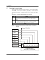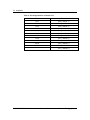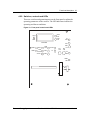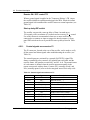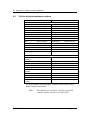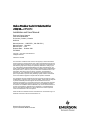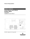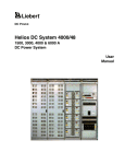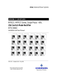
1
Emerson Energy Systems UM5C05C ( 169-2081-501 ) Helios Modular Switch Mode Rectifier 200I/48NT5C05C Installation and User Manual HELIOS V OL T V O LT CA L AM P CUR CA L CL AD J I EQ L AD J TH S D 0 HV SD RF A SEN F A IL FA N A LM EQ L V O L T+ V O U T- E QL A C ON FF 1 1 .0 A F F2 1 .0A F LT CL F LT A DJ A C/C A H VS D A DJ I S T UP DL Y S LS I D C /C C P0745680 Standard 6.00 October 2001 FS 3 Helios Modular Switch Mode Rectifier 200I/48 NT5C05C Installation and User Manual Manual Number : UM5C05C ( 169-2081-501 ) Manual Status : Standard Manual Issue : 6.00 Release Date : October 2001 P0745680 Copyright 2001 Astec International Ltd All Rights Reserved Published in Canada The information contained in this manual is the property of Astec International Ltd and is subject to change without notice. Astec International Ltd reserves the right to make changes in design or components as progress in engineering and manufacturing may warrant. Except as specifically authorized in writing by the V.P. of Engineering and Product Manufacturing of Astec International Ltd, the holder of this manual shall keep all information contained herein confidential and shall protect same, in whole or in part, from disclosure and dissemination to all third parties, and use the same for start-up, operation, and maintenance purposes only. Any modification to the equipment must be approved by the person responsible for product safety and design quality at Astec International Ltd to insure that the equipment complies with the operation standards. This equipment has been tested and found to comply with the limits for a Class A digital device, pursuant to part 15 of the FCC Rules. These limits are designed to provide reasonable protection against harmful interference when the equipment is operated in a commercial environment. The equipment generates, uses, and can radiate radio frequency energy, and if not installed and used in accordance with the instructions contained in the Installation and User Manuals, can cause harmful interference to radio communications. Operation of this equipment in a residential area is likely to cause harmful interference, in which case the user will be required to correct the interference at his own expense. Helios and Helios Candeo are trademarks of Astec International Ltd. The Emerson logo is a trademark and service mark of Emerson Electric Co. Emerson Energy Systems Rectifier 200I/48NT5C05C Installation and User Manual 5 Publication history October 2001 Standard Issue 6.00. Manual restructured and updated to reflect Emerson Energy Systems and Emerson Network Power identities. ( ECN 102-26804 ) March 1998 Issue 5.0. Standard. Reference change from NT5C05CB to NT5C05C. July 1997 Issue 4.0. Standard EMI compliance information and table of content numbering corrections. June 1995 Issue 3.0. Standard. Revised rectifier installation procedure in a cabinet. September 1994 Issue 2.0. Standard. Few revisions and additions from the previous issue. July 1994 Issue 1.0. Standard. Few changes from the previous issue and the document is now rated “Standard” Emerson Energy Systems Rectifier 200I/48NT5C05C Installation and User Manual 6 Publication history This page is left blank intentionally. UM5C05C P0745680 Standard 6.00 October 2001 Emerson Energy Systems 7 Contents 1. General information .................................................................................... 11 1.1. Purpose of this manual .............................................................................. 11 1.2. Models and mounting configurations ......................................................... 12 2. Specifications .............................................................................................. 13 2.1. Mechanical and electrical specifications .................................................... 13 2.2. Operation specifications and ambient conditions....................................... 14 2.3. Mechanical and electrical specifications of a 1200 A cabinet .................... 16 2.4. Ambient conditions of a 1200 A cabinet..................................................... 16 3. Installation.................................................................................................... 17 3.1. Mounting configurations ............................................................................. 17 3.2. Tools and test equipment........................................................................... 17 3.3. Cautions and Warnings.............................................................................. 17 3.3.1. Installing in a frame.............................................................................. 20 3.3.2. Installing in a cabinet ........................................................................... 20 3.4. Cabling and connecting.............................................................................. 22 3.5. Connecting the dc output terminals to the busbars.................................... 23 3.5.1. Securing the dc output terminals to the busbars in a 1200 A cabinet . 24 3.5.2. Running and connecting the dc between busbars and a rectifier ........ 24 3.6. Connecting ac to the rectifiers.................................................................... 24 3.7. Connecting the control signals ................................................................... 28 3.7.1. Monitoring of the shunt current ............................................................ 29 4. Functional description ................................................................................ 31 4.1. Overview .................................................................................................... 31 4.1.1. Input circuit .......................................................................................... 31 4.1.2. Output circuit........................................................................................ 31 4.1.3. Monitoring and control circuits ............................................................. 32 4.1.4. Output capacitors................................................................................. 32 4.2. Description of the front panel ..................................................................... 32 4.2.1. Breakers .............................................................................................. 32 4.2.2. Switches, controls and LEDs ............................................................... 33 4.2.3. Front panel LEDs................................................................................. 34 4.2.4. Local and remote adjustments and controls........................................ 35 4.2.5. Voltage / current displaytest and measurement............................... 36 4.2.6. Float and equalize voltage control ....................................................... 37 4.2.7. Current limit adjustment and rectifier regulating test ........................... 37 4.2.8. Rectifier parallel operation ................................................................... 38 4.2.9. HVSD ( high voltage shutdown ).......................................................... 40 4.2.10. TR ( temporary inhibition ) and sequential start................................... 40 4.2.11. Control signals on connector P1.......................................................... 42 5. Operation...................................................................................................... 45 5.1. Standard settings ....................................................................................... 45 5.2. Starting up and adjusting ........................................................................... 46 Emerson Energy Systems Rectifier 200I/48NT5C05C Installation and User Manual 8 Contents 6. Maintenance................................................................................................. 49 6.1. Replacing the air filter ................................................................................ 49 6.2. Replacing the fan unit ................................................................................ 49 6.3. Calibrating the Volt / Amp Multimeter......................................................... 50 6.4. Resetting the rectifier after an HVSD ( high voltage shutdown )................ 51 7. Troubleshooting .......................................................................................... 53 8. Appendix A : Replacement parts ............................................................... 55 9. Appendix B : Technical service assistance .............................................. 57 9.1. Local toll-free prefixes ................................................................................ 57 9.2. Toll-free technical assistance numbers...................................................... 58 10. Abbreviations and acronyms ..................................................................... 59 List of Figures Figure 1 - Front view of the modular 200I / 48 switch mode rectifier ................... 11 Figure 2 - Typical mounting in a cabinet or frame................................................ 12 Figure 3 - Anchoring the cabinet .......................................................................... 21 Figure 4 - Installing the rectifier............................................................................ 22 Figure 5 - Connecting the dc to the busbars with a shunt on the battery side or a shunt on the ground side ...................................................... 23 Figure 6 - Cabling ac the NT5C05CA / CB rectifiers............................................ 26 Figure 7 - Connect the power leads to the L1, L2 and L3 terminals of the rectifier ................................................................................................. 26 Figure 8 - Connecting ac to the rectifier NT5C05CC ........................................... 27 Figure 9 - Typical connections between rectifiers and the conventional controller .............................................................................................. 28 Figure 10 - Front panel controls and LEDs .......................................................... 33 Figure 11 - Replacing the fan unit ........................................................................ 49 List of Tables Table 1 - Mechanical specifications of the rectifier .............................................. 13 Table 2 - Electrical specifications of the rectifier.................................................. 13 Table 3 - Operation specifications of the rectifier ................................................ 14 Table 4 - Ambient conditions for the rectifier ....................................................... 15 Table 5 - Mechanical specifications of the NT6C43CB 1200 A cabinet .............. 16 Table 6 - Electrical specifications of the NT6C43CB ........................................... 16 Table 7 - Ambient conditions for the NT6C43CB 1200 A cabinet........................ 16 Table 8 - Pin assignment for connectors J7 to J12.............................................. 29 Table 9 - Pin assignment for connector J13 ........................................................ 30 Table 10 - Designation of the LEDs on the front panel ........................................ 34 Table 11 - Adjusting the potentiometers and switches ........................................ 36 Table 12 - Rectifier input / output signals to the controller................................... 36 Table 13 - Setting the start-up delay .................................................................... 41 Table 14 - Control signal connections on P1 ....................................................... 42 Table 15 - Standard settings for the rectifier........................................................ 45 Table 16 - Diagnosing system faults.................................................................... 53 List of Procedures Procedure 1 - Installing the rectifier in a frame .................................................... 20 Procedure 2 - Installing a rectifier in a cabinet..................................................... 21 Procedure 3 - Securing the dc output terminals to the busbars of the cabinet .... 24 Procedure 4 - Typical dc cabling in a frame application ...................................... 24 Procedure 5 - Cabling the ac input to the NT5C05CA / CB rectifiers .................. 25 UM5C05C P0745680 Standard 6.00 October 2001 Emerson Energy Systems Contents 9 Procedure 6 - Connecting the ac male plug between the NT5C05CC rectifier and the ac female plug in a 1200 A cabinet .................................. 27 Procedure 7 - Connecting the NT5C05CC to the controller................................. 28 Procedure 8 - Connecting an NT5C05CC rectifier directly to a controller ........... 29 Procedure 9 - Starting up the rectifier .................................................................. 46 Procedure 10 - Replacing the fan unit ................................................................. 50 Procedure 11 - Calibrating the meter................................................................... 51 Procedure 12 - Resetting the rectifier after a high voltage shutdown .................. 51 Emerson Energy Systems Rectifier 200I/48NT5C05C Installation and User Manual 10 Contents This page is left blank intentionally. UM5C05C P0745680 Standard 6.00 October 2001 Emerson Energy Systems 11 1. General information 1.1. Purpose of this manual This manual provides installation, operation and maintenance information for the NT5C05CA / CB / CC 200I modular switch mode rectifiers with an input voltage of 380 / 415 V ac and an output capacity of 200 A at a nominal voltage of –48 volts. This manual covers all applications of the rectifier referred to as the 200I ( “I” standing for “International” ) market. Figure 1 - Front view of the modular 200I / 48 switch mode rectifier HELIO S V OL T V O LT CA L AM P CU R CA L I CL AD J EQ L AD J TH S D 0 HV SD RF A SEN F A IL FA N A LM EQ L V O L T+ V O U T- A C ON E QL FF 1 1 .0 A F F2 1 .0 A F LT CL F LT A DJ AC/C A H VS D A DJ I S T UP DL Y S LS FS I D C /C C The NT5C05CA / CB / CC rectifiers are designed to operate continuously in a -48 V power system, equipped with or without batteries. It can be integrated into a small-embedded system or a larger power plant configuration. It is forced air-cooled by four fans contained in the unit, one of which is are redundant, if one fan fails this will not cause a shutdown of the rectifier. The rectifiers can be operated in conjunction with other Emerson rectifiers as well as with the models and conventional controllers of other manufacturers available on the market. Emerson Energy Systems Rectifier 200I/48NT5C05C Installation and User Manual 12 General information 1.2. Models and mounting configurations Two models of 200I rectifiers are available : • Models NT5C05CA / CB, without an ac cable • Model NT5C05CC, equipped with an ac cable terminated with a male plug Up to six switch mode 200I rectifiers can be installed in a 23-inch NT6C43CB 1200 A cabinet or in an NT6C40 type frame. The cabinet is specifically designed to provide modularity within a very compact unit. For wooden floor applications in a zone 4 seismic region, up to three rectifiers can be installed in a mounting frame mounting, but they must be installed in the three lowest mounting positions in the frame. Figure 2 - Typical mounting in a cabinet or frame RECTIFIER No. 1 RECTIFIER No. 2 RECTIFIER No. 3 RECTIFIER No. 4 RECTIFIER No. 5 RECTIFIER No. 6 UM5C05C P0745680 Standard 6.00 October 2001 Emerson Energy Systems 13 2. Specifications 2.1. Mechanical and electrical specifications Table 1 - Mechanical specifications of the rectifier 10.0 inches ( 25.4 cm ) Height : Depth : 22.0 inches ( 55.9 cm ) Width : 20.5 inches ( 52.1 cm ) Weight : 92.6 lbs ( 42 kg ) Table 2 - Electrical specifications of the rectifier Nominal : 380 / 415 V ac Input voltage : Range : 330 ±5 V ac to 475 ±5 V ac Frequency : 47 to 63 Hz Note: After an out of range line condition shutdown, the rectifiers will restart automatically at a line voltage within 350 ±5 V ac to 460 ±5 V ac. Nominal: 18 A RMS ( at 415 V ac ) Input current : Worst case: 24 A RMS Input protection : 25 A ac breaker, 3 Ø Output floating voltage : −46 V dc to —58 V dc Equalizing voltage : 0 to −4 V dc above the floating voltage High voltage shutdown : −52 V to −60 V dc Output current : 200 A ( 330 to 475 V ac input ) Output protection : 200 – 250 A dc circuit breaker Current limit : 50% to 105% of the rated output current Emerson Energy Systems Rectifier 200I/48NT5C05C Installation and User Manual 14 Specifications 2.2. Operation specifications and ambient conditions Table 3 - Operation specifications of the rectifier Output regulation : At the output terminals, the voltage is within ±0.5% of the set voltage value for all specified input and output variations, and within ±1% for any combination of specified input, output and ambient conditions. Temperature drift : Unless otherwise stated, all input and output parameters such as input voltage range, output current and voltage, current limit, etc. shall not vary more than 2% over the operating temperature range. Output noise and ripple : • less than 22 dB of random noise on C band at voice frequency over the entire operating range of the rectifier, including operation in the current limit mode, and at low, nominal and high input voltage conditions ( with or without batteries and measured at the point of regulation ) • less than 20 mV RMS in any 3 kHz band between 10 kHz and 20 MHz ( measurements made with or without batteries at the output terminals of the rectifier and with the rectifier in the local sensing mode ) • less than 250 mV peak to peak switching voltage spikes ( measured differentially with an a 100 MHz oscilloscope ) Total harmonic distortion ( THD ) : Less than 5%. Efficiency : Better than 89% at a nominal input voltage of 350 V ac and for an output current ( load ) greater than 80 A. Power factor : Better than 99% with an output current ( load ) greater than 80 A. Heat dissipation : The maximum heat dissipation is 1420 watts ( 4846 BTU / hr ) for an output current ( load ) of 200 A at –58 V dc ( when the ac input is 330-475 V ) Electromagnetic interference ( EMI ) : The NT5C05CA / CB rectifiers when used in the rectifier cabinet NT6C43CA / CB ( equipped with the ac EMI filter kit NT6C18KB, or the NT5C05CC without external EMI filter ) meet the CISPR requirements for conducted and radiated EMI as specified in Publication 22 for Class "A" equipment. Reliability: The rectifier has an MTBF greater than 120 000 hours under normal operating conditions, at 77°F ( 25°C ) as per Telcordia Technologies TR332 method. UM5C05C P0745680 Standard 6.00 October 2001 Emerson Energy Systems Specifications 15 Table 4 - Ambient conditions for the rectifier Operating conditions A minimum airflow clearance of 2 inches ( 5 cm ) is required at the rear of the rectifier. The rectifier will operate properly under the following conditions. Temperature: 32°F to 122°F ( 0°C to +50°C ) 32°F to 104°F ( 0°C to +40°C ) with air filters Humidity: Transportation conditions 0 to 95% RH ( non-condensing ) at 4 kPa max. equiv. to 7,000 ft. ( 2,100 m ) above sea level During transportation, the rectifier can be subjected to the following conditions without sustaining damage. Temperature: –67°F ( –55°C ) for 16 hours 140°F ( +60°C ) dry heat Humidity: 0 to 95% RH ( non-condensing ) at 4 kPa max. Vibration: 38 mm / s max. ( 10 Hz to 30 Hz ) sinusoidal, 18-inch ( 457 mm ) drop when packaged Pressure: 12 kPa min. equiv. to 49,212 ft. ( 15,000 m above sea level) Temperature shock : −58°F to 140°F ( −50°C to 60°C ) Storage conditions During storage, the rectifier may be subjected to the following conditions without damage : Temperature: –67°F ( –55°C ) for 16 hours to 140°F ( +60°C ) dry heat Humidity: 0 to 95% RH ( non-condensing ) at 4 kPa maximum The rectifier contains aluminum electrolytic capacitors that have a shelf life of five years or greater at the maximum rated storage temperature. Emerson Energy Systems Rectifier 200I/48NT5C05C Installation and User Manual 16 Specifications 2.3. Mechanical and electrical specifications of a 1200 A cabinet Table 5 - Mechanical specifications of the NT6C43CB 1200 A cabinet 84.00 inches ( 213.36 cm ) Height : Depth : 23.63 inches ( 60.0 cm ) Width : 23.63 inches ( 60.0 cm ) Table 6 - Electrical specifications of the NT6C43CB 1200 A cabinet 2.4. Input voltage : 380 / 415 V ac three phase Output voltage : –46 V dc to –58 V dc Output current : 1200 A Ambient conditions of a 1200 A cabinet Table 7 — Ambient conditions for the NT6C43CB 1200 A cabinet Operating conditions The cabinet is designed for use under the following ambient conditions. Temperature: 0°C to 50°C ( 32°F to 122°F ) 0° to 40°C ( 32° to 104°F ) with air filters Storage conditions Humidity: 0 to 95% RH ( non-condensing ) Altitude: sea level to 7,000 ft ( 2,100 m ) During transportation and storage, the acceptable ambient conditions are : Temperature: –55°C ( –67°F ) +60°C ( 140°F ) dry heat Humidity: UM5C05C P0745680 Standard 6.00 October 2001 0 to 95% RH ( non-condensing ) Emerson Energy Systems 17 3. Installation 3.1. Mounting configurations The NT5C05CA / CB / CC rectifiers are designed for installation in a 1200 A cabinet ( NT6C43CB ) or in a standard frame ( NT6C40 or equivalent ). In this chapter, a different procedure is provided for each mounting method. The rectifiers are shipped loose, not mounted in the frame or cabinet. Upon reception, remove the rectifier from its shipping carton and inspect it for physical damage. Report any damage to your immediate supervisor. 3.2. Tools and test equipment The following tools and test equipment are required : • screwdriver, flat blade, 3/16 inch ( 5 mm ) • potentiometer screwdriver, Bourns No. 60, or equivalent • heavy cable strippers or electrician’s knife • heavy cable cutters ( AWG 4/0 or metric No. 110 ) • nut drivers ( set ) • socket set ( 1/2 inch or 15 mm drive ) • torque limiting wrench ( 1/2 inch. or 15 mm drive ) • crimper, T&B, 15CA54R Violet die • digital multimeter, Fluke 8000A or equivalent 3.3. Cautions and Warnings The following precautions must be adhered to at all times when handling and installing power equipment. CAUTION Protecting the premises Protect the floors and walls against damage with sheets of plywood, cardboard, or other suitable material when handling the equipment. Emerson Energy Systems Rectifier 200I/48NT5C05C Installation and User Manual 18 Installation CAUTION Preventing damage caused by over-tightening Do not over-tighten nuts and bolts. Over-tightening can strip the threads or break the bolts. Apply the appropriate torque values. CAUTION Personal safety and protecting the equipment Use a dolly truck, forklift, or hoist whenever possible when handling and moving the equipment, as power equipment is heavy. If a forklift is used, do not remove the packing material before having moved the equipment to its final location. If a dolly truck is used, the packing material can be removed in the reception area. When handling cabinets with equipment installed in them, exercise care to ensure they do not tip over, as they can be top heavy. CAUTION Preventing personal injury When cutting material, wear gloves and goggles. Break all corners and sharp edges with a flat file. CAUTION Optimizing the life of the equipment Make sure there are no obstructions in front of the ventilation openings that can restrict the flow of air. UM5C05C P0745680 Standard 6.00 October 2001 Emerson Energy Systems Installation 19 WARNING Generator requirements for Emerson Energy Systems Power Systems For information on selecting ac generators that will effectively maintain peak performance and operating characteristics, for all Astec APS power systems, go to the partners’ section of the Emerson Energy Systems web site at www.EmersonEnergy-NA.com. To obtain access to the partners’ section follow the instructions found on the partner’ page, or dial our nearest local 1−800 technical support line ( refer to “Appendix C : Technical service assistance” of this manual for the telephone number ). DANGER Grounding The frame ground leads must be connected before any other leads. This is to prevent the cabinets and any other metal structures from carrying dangerous ac or dc voltage levels. DANGER Protecting against electrical shocks The cabling of the power plant, and all other required cabling, must be carried out by qualified personnel and in conformance with local and national electrical codes. AC input voltages to the rectifiers are at a dangerous level. Ensure that the circuit breakers are locked in the OFF position in the ac service panel before working on the power plant. Dangerous voltages may be present at the output dc terminals even if the rectifiers are OFF. Use a voltmeter to verify for the presence of such voltages. Do not put the circuit breakers to ON until the entire system has been assembled and you have been instructed to do so. Verify, and identify with a tag, the proper polarity of the battery leads before connecting them to the power plant. Emerson Energy Systems Rectifier 200I/48NT5C05C Installation and User Manual 20 Installation DANGER Short circuit hazard The rectifiers, and the batteries in particular, can deliver high current if a short to ground occurs. When working on live equipment, remove all personal jewellery, use properly insulated tools, and cover any live busbars with a insulating sheet of canvas to prevent short circuits that could be caused by falling tools or parts. 3.3.1. Installing in a frame When shipped, the NT5C05CA / CB / CC switch mode rectifiers are configured for installation in a standard frame. As the rectifier is heavy, use a manual forklift to mount the rectifier in a frame. If a forklift is not available, two persons, exercising care, can lift the rectifier into place and secure it. Procedure 1 - Installing the rectifier in a frame Step 1 Action Note : Install each rectifier beginning with the lowest mounting position in the frame. Align the mounting brackets of the rectifier with the mounting holes in the frame and insert the locating pins into these holes. 2 Lift the rectifier and align the middle holes in the mounting brackets of the rectifier with the locating pins inserted in the frame. Slide the rectifier into position onto the locating pins. 3 Secure the rectifier to the frame by inserting and tightening a mounting screw ( provided ) in the uppermost holes of each mounting bracket ( one on the left side and one on the right side ). 4 Remove the locating pins and install the other six mounting screws. Tighten the screws applying a torque of 6.5 ± 0.5 ft-lbs ( 8.5 ± 0.5 N-m ). end 3.3.2. Installing in a cabinet The cabinet is 23.56 inches ( 600 mm ) wide and deep, and 84 inches ( 2134 mm ) high. The anchors provided to secure the cabinet in place are intended for installation on 3000 psi ( 2 kg per sq. mm ) compressive strength concrete. Anchors for seismic applications are available upon request. Slotted holes are provided in the base of the cabinet for anchoring. The primary locations should be used as a first choice ( see Figure 3 ). If a steel-reinforcing rod is encountered when drilling the holes for the anchors UM5C05C P0745680 Standard 6.00 October 2001 Emerson Energy Systems Installation 21 in the concrete floor, the secondary anchor locations may be used. An optional cabinet isolation kit is available consisting of four anchor bushings and a base pad. If this kit is installed, place the pad on the floor and the bushings on the anchors, and position the cabinet on top. Figure 3 - Anchoring the cabinet 590 mm (23.13 po.) 520 mm (20.42 po.) 600 mm (23.56 po.) SECONDARY LOCATION FOR FLOOR ANCHORS + PRIMARY LOCATION FOR FLOOR ANCHORS + 526 mm (20.68 po.) Procedure 2 - Installing a rectifier in a cabinet Step Action 1 Loosen and remove the screws securing the mounting brackets to each side of the rectifier. 2 Reposition and secure the mounting brackets to the holes located nearest the front of the rectifier, on each side of the rectifier. 3 Remove the blank panel from the cabinet and put the self tapping screws in a secure location, for future use. continued Emerson Energy Systems Rectifier 200I/48NT5C05C Installation and User Manual 22 Installation Procedure 2 - Installing a rectifier in a cabinet ( continued ) Step Action 4 Place the rectifier on the L-shaped guides located in the lowest position of the cabinet and slide it towards the rear until the mounting brackets come into contact with the frame of the cabinet. The front of the rectifier should be flush with the front of the cabinet and the output bussing should be in contact with the riser busbars located at the rear of the cabinet. 5 Align the mounting holes in the brackets of the rectifier with the mounting holes in the frame. Secure the rectifier in place by inserting and tightening the self-tapping screws removed in Step 3. Note : Install an external tooth lock washer on one of the screws to assure good ground continuity between the rectifier and the frame. end Figure 4 - Installing the rectifier HELIOS VOLT CAL CUR CAL VOLT AMP EQL ADJ EQL VOLT/AMP THSD AC/CA HVSD SEN FAIL AC ON FAN ALM EQL CL VOUT+ VOUT- RFA SELF-TAPPING SCREW ( P097F813 ) CL ADJ FLT FF1 1.0A FF2 1.0A FLT ADJ HVSD ADJ ST UP DLY SLS DC/CC HELIOS 3.4. FS ET LOCK WASHER VOLT CAL Cabling and connecting The ac cables of the rectifier must always exit each rectifier from the right side, when viewed from the rear. The dc cables of the rectifier must always exit each rectifier from the left side, when viewed from the rear. The system alarm interface cable must always exit each rectifier from the right side, when viewed from the front. UM5C05C P0745680 Standard 6.00 October 2001 Emerson Energy Systems Installation 23 3.5. Connecting the dc output terminals to the busbars The dc outputs of the rectifier are connected to the busbars as illustrated in Figure 5. There are two methods : • BAT GRD ( + ) of the rectifier connected to the CHG/ DISCH GRD busbar and the –48 V of the rectifier connected to the CHG BAT busbar • BAT GRD ( + ) of the rectifier connected to the CHG GRD busbar and the -48V of the rectifier connected to the CHG/ DISCH BAT busbar Figure 5 - Connecting the dc to the busbars with a shunt on the battery side or a shunt on the ground side + CHG / DISCH GRD BUSBAR LOAD + BAT GRD RECTIFIER - -48V - CHG BAT BUSBAR SHUNT DISCHARGE BAT BUSBAR FUSE PANEL SHUNT ON THE BATTERY SIDE + CHG GRD BUSBAR SHUNT DISCHARGE GRD BUSBAR + BAT GRD RECTIFIER - -48V LOAD CHG / DISCH BAT BUSBAR FUSE PANEL SHUNT ON THE GRD SIDE ( PREFERRED CONFIGURATION ) Emerson Energy Systems Rectifier 200I/48NT5C05C Installation and User Manual 24 Installation 3.5.1. Securing the dc output terminals to the busbars in a 1200 A cabinet For cabinet applications, no dc cabling is required; the output terminals of the rectifier are connected directly to the busbars. Procedure 3 - Securing the dc output terminals to the busbars of the cabinet Step Action 1 Connect the BAT GRD output terminal of the rectifier to the BR busbar, and the –48 V output terminal of the rectifier to the –48 V busbar located at the rear of the cabinet. 2 Tighten the bolts by applying a torque of 6.5 ± 0.5 ft-lbs ( 8.5 ± 0.5 N-m ). end 3.5.2. Running and connecting the dc between busbars and a rectifier For frame applications, use terminal lug A0361762, supplied with the unit, and no. 110 ( 4/0 ) metric cable. Procedure 4 - Typical dc cabling in a frame application Step Action 1 Connect the BAT GRD output terminal of the rectifier to the CHG GRD busbar of the power plant. Connect the –48 V output terminal of the rectifier to the CHG / DISCH BAT busbar of the power plant ( see Figure 5 ). 2 Apply a torque of 6.5 ± 0.5 ft-lbs ( 8.5 ± 0.5 N-m ) on the bolts securing the lugs to the rectifier terminals. end 3.6. Connecting ac to the rectifiers WARNING Electrical connections should meet standards The electrical installation must be carried out by qualified personnel and in accordance with local electrical codes. UM5C05C P0745680 Standard 6.00 October 2001 Emerson Energy Systems Installation 25 DANGER Hazardous potentials Input voltage to the cabinet is at a hazardous potential. Make sure the power is OFF and that the lever in the ac service panel is locked in the OFF position before attempting to connect the input line voltage to the ac box of the cabinet. Procedure 5 - Cabling the ac input to the NT5C05CA / CB rectifiers Step Action 1 Install the ac breaker ( 30 A / 3 phase per rectifier ) in the 380 / 415 volts ac service panel and lock it in the open ( OFF ) position. 2 Put the ac breaker to OFF. 3 Run the ac armored cable ( metric no. 25 [ 10 AWG ] 3 conductors and ground ) from the service panel, through the top of the cabinet, to the rear of the rectifier. 4 Secure the ac cable to the side of the cabinet using cable ties and adhesive anchors. Make sure the cable are located in a manner that will not interfere with the insertion of the rectifier ( see Figure 6 ). 5 Ground the conduit sheath to the ac service panel. Insulate the conduit connector at the rectifier end with electrical tape to isolate it from the ac ground. 6 Remove the two ac protection plates located at the rear of the rectifier. 7 Strip 10 inches ( 250 mm ) of armored insulation from the end of the ac cable. Insert the wires in the 90° conduit connector ( see Figure 7 ). 8 Run the signal cable from the rectifier to the interconnect board or controller as described in the "Control signal connections" section. 9 Connect the green ground wire to the FR GND terminal. 10 Connect the power leads to the L1, L2 and L3 terminals ( any phase sequence ) ( see Figure 7 ). 11 Tighten the elbow connector and reassemble the ac protection plate. 12 Run the signal cable from the rectifiers to the interconnect board or controller as specified in the " Connecting the control signals" section. 13 Secure the signal cables to the insulating busbar support, located in the cabinet, with cable ties. 14 Start-up the rectifier as described in the “ Start-up “ procedure. end Emerson Energy Systems Rectifier 200I/48NT5C05C Installation and User Manual 26 Installation Figure 6 - Cabling ac the NT5C05CA / CB rectifiers SIGNAL CABLES TO THE PLANT CONTROLLER AC FEED TO RECTIFIERS PART OF OPTIONAL KIT P0872151 A CABLE TIE A SIGNAL CABLE Note: Dress the cables carefully to clear the insertion path of the rectifier. HEX HEAD CAP SCREW AND WASHERS ( 4 PLACES ) SECTION A-A REMOVE PLATE TO ACCESS CONNECTORS SHOWING TOP VIEW OF AC CABLING REAR VIEW OF A TOP FED ARRANGEMENT SHOWING OPTIONAL BUSBAR COVER KIT P0872151 ( WITH REAR PANELS REMOVED ) Figure 7 - Connect the power leads to the L1, L2 and L3 terminals of the rectifier UM5C05C P0745680 Standard 6.00 October 2001 Emerson Energy Systems Installation 27 Procedure 6 - Connecting the ac male plug between the NT5C05CC rectifier and the ac female plug in a 1200 A cabinet Step Action 1 Install the ac breaker ( 30 A / 3 phases per rectifier ) in the 380 / 415 volts ac service panel. 2 Put the ac breaker for the NT5C05CC rectifier, located in the ac service panel, to OFF. 3 Run the metric no. 25 ( 10 AWG ) ac supply cable ( 3 conductors and ground ) to the female receptacle ( see Figure 8 ). Connect the female connector to the male connector. 4 Run the signal cable from the rectifier to the interconnect board or controller as specified in the " Connecting the control signals " section. 5 Secure the signal cables to the insulating busbar support, located in the cabinet, with cable ties. 6 Start-up the rectifier as described in the “ Start-up “ section. end Figure 8 - Connecting ac to the rectifier NT5C05CC A A BROWN BLACK BLUE TB1 L1 L2 L3 GRD CONNECTION R1 (TB1-L1) S2 (TB1-L2) T3 (TB1-L3) WIRE COLOR BLUE BROWN BLACK GREEN / YELLOW GREEN/YELLOW SECT A-A FEMALE CONNECTOR Emerson Energy Systems Rectifier 200I/48NT5C05C Installation and User Manual 28 Installation 3.7. Connecting the control signals For all applications with conventional controllers ( such as NT6C25BA or NT6C25BB ) or front access controllers ( NT6C25FA ), execute the steps contained in Procedure 7 to connect the NT5C05CC rectifier ( see Figure 9 ). Procedure 7 - Connecting the NT5C05CC to the controller Step Action 1 Connect each rectifier to the NT6C43PB board ( positions J1 to J6 ), located at the top front of the cabinet or frame, with P0747000 cables. 2 • Connect the NT6C43PB board ( positions J7 to J12 ) to the controller with P0736355 cables for conventional controllers ; and with P0736268 cables for front access controllers. end Figure 9 - Typical connections between rectifiers and the conventional controller Cables P0747000 Rectifier #6 Rectifier #5 Rectifier #4 Rectifier #3 Rectifier #2 Rectifier #1 NT6C43PB J13 MONITOR J1 J2 J3 J4 J5 J6 J7 J8 J9 J10 J11 J12 Cables P0736355 CONTROLLER NT (NT6C25BA or NT6C25BB) UM5C05C P0745680 Standard 6.00 October 2001 Emerson Energy Systems Installation 29 Procedure 8 - Connecting an NT5C05CC rectifier directly to a controller Step 1 Action If an NT6C43PB interconnect board is not available, each rectifier must be connected directly to the controller with the following cables : • P0723784, P0723785 or P0723786 ( for conventional controllers ) • P0723708, P0723709 or P0723210 ( for front access controllers ) end For controllers not manufactured by Emerson Energy Systems see Table 12 in the " Functional Description " chapter describing the pin assignments of the rectifier. Refer to Table 8 for the pin assignments of connectors J7 to J12 on board NT6C43PB. Note: The alarm and control signals in Table 8 are all ground signals except for the RC– signal that is a –48 V battery signal. Table 8 - Pin assignment for connectors J7 to J12 Pin Label Function Input/ Output 1 EQL Equalize Input 2 RG+ Remote sense Input 3 RC– Remote sense Input 4 FAN ALM Fan fail alarm Output 5 HVSDR 6 HVSD 7 RFA 8 TR High voltage shutdown reset Input High voltage shutdown Input Rectifier failure alarm Temporary release Output Input 3.7.1. Monitoring of the shunt current A 12-pin connector ( J13 ) is also available on the NT6C43PB interconnect board for monitoring the individual output current shunt readings ( 250 A / 50 mV for example ) of each rectifier in a cabinet or a frame ( see Table 9 ). Emerson Energy Systems Rectifier 200I/48NT5C05C Installation and User Manual 30 Installation Table 9 - Pin assignment for connector J13 Pin Function J13-1 SH+ ( rectifier 1 ) J13-2 SH− ( rectifier 1 ) J13-3 SH+ ( rectifier 2 ) J13-4 SH− ( rectifier 2 ) J13-5 SH+ ( rectifier 3 ) J13-6 SH− ( rectifier 3 ) J13-7 SH+ ( rectifier 4 ) J13-8 SH− ( rectifier 4 ) J13-9 SH+ ( rectifier 5 ) J13-10 SH− ( rectifier 5 ) J13-11 SH+ ( rectifier 6 ) J13-12 SH− ( rectifier 6 ) UM5C05C P0745680 Standard 6.00 October 2001 Emerson Energy Systems 31 4. Functional description 4.1. Overview 4.1.1. Input circuit The input circuit offers the following characteristics : • ac rectifying • EMI filtering • inrush current limiting, a walk-in circuit limits the output current rise to 25 A per second • low and high ac inhibit • power factor compensation • surge voltage protection • ac breaker for input protection For all input and output conditions specified in this manual, when the rectifier is turned on, the ac current will not exceed the maximum steadystate value. 4.1.2. Output circuit The output circuit offers the following characteristics : • shunt for output dc current sensing • 225 A dc circuit breaker for output protection Emerson Energy Systems Rectifier 200I/48NT5C05C Installation and User Manual 32 Functional description 4.1.3. Monitoring and control circuits The monitoring and control circuits offer the following characteristics : • soft start • rectifier fail alarm ( RFA ) • control for local and remote equalize ( EQL ) • temporary release ( TR ) • thermal shutdown ( THSD ) • input ac monitoring • local and remote high voltage dc shutdown ( HVSD ) • local and remote HVSD reset • fan failure detection 4.1.4. Output capacitors The output capacitors will be completely discharged ( < 2 V ) two minutes after the ac power has been removed and the rectifier has been disconnected from the batteries or the parallel rectifiers. 4.2. Description of the front panel 4.2.1. Breakers DC circuit breaker A dc circuit breaker is provided to protect against current overload and to manually disconnect from the power plant. When the breaker is in the 0 ( OFF ) position, an RFA is triggered and the remote sense leads RG+ and RC– are internally disconnected. The rectifier will continue to operate, allowing the adjustment of the FLT, EQL and HVSD set points. AC breaker The input ac circuit breaker can be used to locally turn the rectifier ON or OFF. The local ON / OFF control overrides any remote control signals ( for example, TR ). Putting the breaker to OFF causes an RFA to be issued and the RFA LED to light up, as long as the rectifier output is connected to batteries. UM5C05C P0745680 Standard 6.00 October 2001 Emerson Energy Systems Functional description 33 4.2.2. Switches, controls and LEDs There are switches and potentiometers on the front panel to adjust the operating parameters of the rectifier. The LED indicators indicate the operating and alarm conditions. Figure 10 - Front panel controls and LEDs VOLT VOLT CAL AMP CUR CAL CL ADJ EQL ADJ VOLT/AMP THSD RFA HVSD FAN ALM VOUT+ SEN FAIL EQL EQL AC ON CL FF1 1.0A FF2 1.0A FLT FLT ADJ VOUT- HVSD ADJ ST UP DLY SLS FS DC/CC Emerson Energy Systems Rectifier 200I/48NT5C05C Installation and User Manual 34 Functional description 4.2.3. Front panel LEDs Table 10 - Designation of the LEDs on the front panel LED Color Description AC ON Green Input ac voltage operational CL Yellow Current Limit EQL Yellow Rectifier is in equalize mode FAN ALM Red Fan fail alarm HVSD Red High voltage shutdown RFA Red Rectifier fail alarm SEN FAIL Red Remote sense fail THSD Red Thermal shutdown AC ON ( ac voltage monitoring ) The rectifier monitors the input voltage and if the voltage exceeds the set limit, it will inhibit its operation and trigger a rectifier failure alarm ( RFA ). The rectifier will resume its normal operation automatically when the specified input voltage has been re-established. CL ( current limit indicator ) This LED lights up if the rectifier is in current limit. The rectifier limits the output current to 205 A + 5 A ( adjusted in the factory ), 50% to 105% of the rated output current. EQL ( equalize ) Indicates the rectifier is in equalizing mode. FAN ALM ( fan failure alarm ) This LED lights up when the FAN ALM is activated due to a defect in the fan system. The fan configuration includes redundancy to ensure the rectifier will continue working properly if one of the fans fails. If only one fan fails, a rectifier failure alarm RFA will not be triggered. It is, however, imperative to repair or change the fan unit as soon as possible to preserve this redundant feature. UM5C05C P0745680 Standard 6.00 October 2001 Emerson Energy Systems Functional description 35 HVSD ( high voltage shutdown ) The rectifier monitors itself for high voltage and will shut down when its output voltage exceeds a preset adjustable value ( between -52 V and -60 V ). RFA ( rectifier failure alarm ) The rectifier monitors its operation and triggers a global RFA if it detects an internal failure, causing the RFA LED to light up. One of the following will trigger an alarm : • abnormal or out of range ac input voltage • output fuse failure • system or internal shutdown ( thermal, HVSD, TR ) • internal failure causing a power switching malfunction If the switching malfunction is caused by an improper adjustment of the output float voltage, the RFA alarm will not be triggered. The RFA feature will be activated if the ac power is removed in a system where batteries are present. SEN FAIL ( sense fail alarm ) This LED lights up if the remote sense leads are not connected, or if the RC fuse has blown. THSD ( thermal shutdown ) This LED lights up when the rectifier is protecting itself against overheating by suspending its operation for the duration of the high temperature condition. An RFA alarm will also be triggered. 4.2.4. Local and remote adjustments and controls The current and voltage calibration, adjustment and control can be set through potentiometers and switches ( see Table 11 ) located on the front panel, or by remote signals sent from the controller ( see Tables 8 and 12 ). Emerson Energy Systems Rectifier 200I/48NT5C05C Installation and User Manual 36 Functional description Table 11 - Adjusting the potentiometers and switches Potentiometers CL ADJ Description Current limit adjust ( 100 A to 210 A ) CUR CAL Current reading calibration EQL ADJ Equalize voltage adjust ( 0 V to −4 V ) FLT ADJ Float voltage adjust ( −46 V to −58 V ) HVSD ADJ High voltage shutdown adjust ( −52 V to −60 V ) VOLT CAL Voltage reading calibration Switches EQL / FLT SLS / FS ST UP DELAY VOLT / AMP Description Equalize / Float selection switch Slope load sharing / Forced load sharing selection Start-up delay selection DIP ( 4 sec to 2 min ) Voltage and current display selection switch Table 12 - Rectifier input / output signals to the controller Designation Description RG+ / RC− External reference voltage across the batteries measured through the controller to regulate the voltage. HVSD HVSDR TR Remote High Voltage Shutdown input activated by a BAT RTN signal. Remote High Voltage Shutdown Reset input activated by a BAT RTN signal. Remote Inhibit input activated by a BAT RTN signal. EQL Remote Equalize input activated by a BAT RTN signal. RFA Rectifier Failure Alarm output activating a form C contact F ALM Fan Failure Alarm output activating a form C contact SHUNT ( + ) and SHUNT ( − ) Rectifier Current input / output ( 50 mV / 250 A ) CURRENT SHARE Common Forced Current Share Mode ( 0-12 V ) 4.2.5. Voltage / current display test and measurement CUR CAL / VOLT CAL potentiometers These potentiometers are used to calibrate the digital display meter for current and voltage measurements. As the two potentiometers affect each other, current calibration must be performed before voltage calibration. UM5C05C P0745680 Standard 6.00 October 2001 Emerson Energy Systems Functional description 37 VOLT / AMP digital meter switch This switch is used to select the measurement display mode of the digital meter. The output voltage or the output current modes can be selected. VOUT+, VOUT− − test points These test points are used to measure the voltage at the point of regulation. A 5 kohm resistor is placed in series with both sensing leads to prevent short-circuits at the jack terminals. The resistor may affect reading accuracy, depending on the impedance of the meter. Refer to the Instruction Manual for your meter to determine its internal impedance and correction factor. 4.2.6. Float and equalize voltage control Local FLOAT / EQL switch and potentiometers The rectifier is equipped with a FLOAT / EQL switch. When the FLOAT / EQL switch is held in the EQL position, the rectifier goes into equalize mode and boosts the output voltage to the value set by the EQL potentiometer. When the switch FLOAT / EQL is held in the FLT position, the rectifier delivers a float voltage set by the FLT potentiometer. Remote equalize control EQL The rectifier is equipped with remote equalize control. This control is activated by a remote ground signal ( BAT RTN ). The rectifier returns to normal ( float voltage ) operation when this signal is removed. 4.2.7. Current limit adjustment and rectifier regulating test CL ADJ potentiometer The rectifier limits the output current to a select value ranging from 100 A to 210 A, set by the CL ADJ potentiometer. The factory adjustment is 205 A ±5 A. Extended periods of operation in the current limiting mode and repeated transitions between constant-voltage operation and constantcurrent operation have no detrimental effect on the performance or service life of the rectifier. Emerson Energy Systems Rectifier 200I/48NT5C05C Installation and User Manual 38 Functional description The rectifier can be started when it is connected across a completely discharged battery without requiring human intervention or operating protective devices. A transition from constant voltage operation to constant current operation and from constant current operation to constant voltage operation occurs automatically, as determined by the output current. The current limiting circuit is functional in float and equalize modes. 4.2.8. Rectifier parallel operation The rectifier can operate in parallel with other rectifiers having similar output characteristics. It shares the total load in proportion to its output rating. Two methods for sharing load current are available : • Slope sharing • Forced sharing Selecting either mode is done by setting the two bottom DIP switches, SLS / FS, located on the front panel. The rectifier is factory set to the slope sharing mode. Slope sharing ( SLS ) When both bottom DIP switches are set to the SLS position, conventional load sharing is achieved through a -300 mV slope on the output voltage of the rectifier, from no load to full load. This mode should be used when rectifiers from different manufacturers are not all equipped with the forced load-sharing feature. In this mode, the units will share the load within ±10% of their maximum output rating. To accurately preset the float voltage of the rectifier, its current in the plant environment must be predicted and the preset output floating voltage must be calculated using the formula found below. In the formula, 0.8 volts is added to the float voltage to compensate for an internal voltage drop when the rectifier dc breaker is put in the ON position. V ( preset ) = Vo ( desired ) + 0.8 V + ( Io ( running ) x 300 mV ) 200 UM5C05C P0745680 Standard 6.00 October 2001 Emerson Energy Systems Functional description 39 Example 1 : If the rectifier is expected to provide 100 A at 48 V V ( preset ) = 48 V + 0.8 V + ( 100 x 300 mV ) 200 V ( preset ) = 48 V + 0.8 V + 0.15 V = 48.95 V Example 2 : If the rectifier is expected to provide 40 A at 48 V V ( preset ) = 48 V + 0.8 V + ( 40 x 300 mV ) 200 V ( preset ) = 48 V + 0.8 V + 0.06 V = 48.86 V Forced sharing ( FS ) When both bottom DIP switches ( SLS / FS ) are set to the FS position, forced load sharing is achieved by an internal control circuit that modifies the loop reference to equally share the output currents between rectifiers. The setting of the output voltage is not modified with changes in output load, as is the case in the slope share mode. In this mode, the rectifiers will share the load within ±2 % of their maximum output rating. For this to occur the rectifiers must communicate their operating current to the other rectifiers in the same power plant. The current share terminal of all the rectifiers ( P1-17 ) in the same power plant must be connected through the control cables and controller. In applications using the NT6C43PB interconnect board, such a connection is implemented automatically. Adjust the rectifier float voltage to the desired system float voltage, plus 0.8 volts, to compensate for an internal drop when the rectifier dc breaker is put in the ON position. Example 3 : for 48 V float voltage V ( preset ) = 48 V + 0.8 V = 48.8 V Emerson Energy Systems Rectifier 200I/48NT5C05C Installation and User Manual 40 Functional description 4.2.9. HVSD ( high voltage shutdown ) HVSD ADJ ( high voltage shutdown adjust ) potentiometer Use this potentiometer to set the internal threshold level at which the local high voltage shutdown condition should occur. Remote HVSD In addition to the local high voltage shutdown feature, the controller of the power plant controller can shut down any rectifier by sending a high voltage shutdown signal, ground ( BAT RTN ) pulse. The rectifier will shut down within 50 ms if it is supplying more than 10% of its full load rating. As is the case for the internal high voltage shutdown condition, two HVSD events must occur within an interval of two minutes to lock out the rectifier permanently. An ac breaker reset or an HVSDR signal can be used to restart the rectifier. Local and remote HVSD reset The rectifier may be reset from an HVSD condition locally by : 4.2.10. • toggling the ac circuit breaker to OFF then to ON ( or the ac breaker in the distribution panel ) • sending a remote ground signal to the HVSDR input through the controller restart ( provided the 'TR' lead has not been activated ) TR ( temporary inhibition ) and sequential start Sequential start The TR input can be interfaced to an external sequential start circuit. UM5C05C P0745680 Standard 6.00 October 2001 Emerson Energy Systems Functional description 41 Table 13 - Setting the start-up delay SWITCH # 1 0 6 5 4 3 POSITION 1 1 NOTE: Switches 3 to 6 ( top four switches ) are used to set the start-up delay. POSITION 1 4 SEC DELAY 0 68 SEC X 6 X 5 X X 4 X X 3 X X 6 X 5 X 4 3 X X X X 20 SEC X X 3 X 6 X X 28 SEC X X X X 3 X X 5 X 92 SEC X 4 6 84 SEC X X X 5 76 SEC X X 5 4 12 SEC X 6 2 DELAY 0 36 SEC X 100 SEC X X 4 X X 3 X X 6 5 X 4 3 44 SEC X X X X X 6 X X 52 SEC 5 X 4 X X X 6 X X 60 SEC X 5 X X 4 X X 3 X X Emerson Energy Systems 116 SEC X X 3 108 SEC X 124 SEC Rectifier 200I/48NT5C05C Installation and User Manual 42 Functional description Remote ON / OFF control TR When a ground signal is applied to the 'Temporary Release' ( TR ) input, the rectifier inhibits its operation and triggers the RFA. When the remote ground signal is discontinued the rectifier returns to normal operation ( see Table 14 ). Start up delay DIP switch The rectifier can provide a start-up delay of from 4 seconds up to 120 seconds, with a resolution of 8 seconds and an accuracy of +1 second. Use of this feature is recommended when two or more rectifiers are connected to a common ac input to stagger the inrush currents. A front panel DIP switch can be set to provide the start-up delays listed in Table 13. 4.2.11. Control signals on connector P1 The P1 connector, located at the rear of the rectifier, can be used to verify all the control and alarm signals when troubleshooting the rectifier ( see Table 14 ). The control inputs are activated by a ground ( BAT RTN ) signal. The alarms, extended by relay contacts, are isolated from each other and the rectifier frame. All contacts are rated 60 V and 0.5 A dc. The normal status of each contact is defined when the rectifier operates normally in the remote sense mode with no alarm. Contacts NC ( normally closed ) and NO ( normally opened ) refer to the de-energized state of their relay coils. Table 14 - Control signal connections on P1 Connection Signal P1-1 EQL Description Equalize P1-2 RC − P1-3 HVSDR Remote sense ( − ) P1-4 RFA ( NC ) P1-5 FAN ALM ( NC ) P1-6 FAN ALM ( C ) P1-7 SH− P1-8 RFA ( NO ) P1-9 SENSE ( C ) P1-10 SENSE ( NO ) High voltage shutdown reset Rectifier fail alarm ( NC ) Fan fail alarm ( NC contact ) Fan fail alarm ( C ) Output current shunt voltage ( - ) Rectifier fail alarm ( NO ) Sense fail alarm ( C ) Sense fail alarm ( NO ) continued UM5C05C P0745680 Standard 6.00 October 2001 Emerson Energy Systems Functional description 43 Table 14 - Control signal connections on P1 ( continued ) Connection Signal P1-11 NC No connection P1-12 NC No connection P1-13 CB OFF ( NC ) P1-14 RG+ P1-15 TR P1-16 HVSD P1-17 CURRENT SHARE P1-18 RFA ( C ) P1-19 SH+ P1-20 FAN ( NO ) P1-21 GRD P1-22 SENSE FAIL ( NC ) P1-23 NC No connection P1-24 NC No connection P1-25 CB OPEN ( C ) Emerson Energy Systems Description Output breaker OFF ( NC ) Remote sense ( + ) Rectifier temporary released by controller High voltage shutdown Forced share link Rectifier fail alarm ( C ) Shunt ( + ) Fan fail ( NO ) Reference ground Sense fail alarm ( NC ) Output breaker OFF ( C ) Rectifier 200I/48NT5C05C Installation and User Manual 44 Functional description This page is left blank intentionally. UM5C05C P0745680 Standard 6.00 October 2001 Emerson Energy Systems 45 5. Operation 5.1. Standard settings The parameters of the NT5C05CA / CB / CC rectifiers are set as indicated in Table 15. For different settings refer to User Manual Voltage_level entitled Voltage Level Limits for Power Plants, Rectifiers and Controllers. Table 15 - Standard settings for the rectifier Parameter Setting Rectifier float output voltage ( FLOAT ) 52.1 ±0.1 V dc Rectifier equalize output voltage ( EQUALIZE ) 52.8 ±0.1 V dc Rectifier high voltage shutdown threshold 56.5 ±0.1 V dc Rectifier output current limit Rectifier start delay 205 A ±5 A 4 sec Low ac input disconnect 330 ±5 V ac Low ac input reconnect 350 ±5 V ac High ac input disconnect 475 ±5 V ac High ac input reconnect 460 ±5 V ac Load sharing method Emerson Energy Systems Slope Rectifier 200I/48NT5C05C Installation and User Manual 46 Operation 5.2. Starting up and adjusting Procedure 9 - Starting up the rectifier Step Action 1 Put the dc circuit breaker to OFF ( 0 position ). Open the sensing leads by removing the corresponding RC fuse ( when the rectifier is used with a controller ) or by disconnecting the alarm and control cable ( when the rectifier is used without a controller ). 2 Put the ac circuit breaker in the main ac service panel to ON. 3 Put the 25 A, 3Ø, ac circuit breaker of the rectifier being tested to ON. The green ac ON LED should light up. Note : The output capacitors are precharged automatically when the dc cables are connected at the rear of the rectifier. 4 Put the meter selector to the VOLT position. The meter will display the voltage value to which the rectifier has been adjusted. 5 Connect a digital multimeter to test points VOUT+ and VOUT– on the front panel. The voltage reading should be within 1% of the rectifier meter reading. If not, calibrate it as described in the “ Maintenance ” section. 6 Determine the system requirements for float, equalize and HVSD limits by referring the User Manual Voltage_Level entitled Voltage Level Limits for Power Plants, Rectifiers and Controllers. 7 If the factory threshold limits of the rectifier must be verified or changed, go to Step 8; otherwise go to Step 14. Adjusting the high voltage shutdown ( HVSD ) 8 Put the dc circuit breaker to OFF ( O ). 9 Turn the HVSD potentiometer fully clockwise. 10 Turn the FLT potentiometer slowly clockwise to set the output voltage on the display of the rectifier to the required HVSD threshold. The EQL / FLT switch and the EQL potentiometer are used if the voltage cannot be set with the FLT potentiometer. 11 Turn the HVSD potentiometer counterclockwise until the rectifier shuts down. 12 Turn the FLT potentiometer counterclockwise two turns and put the ac breaker to OFF. 13 Wait a few seconds for the rectifier to shut down and put the ac breaker to ON to reset it. continued UM5C05C P0745680 Standard 6.00 October 2001 Emerson Energy Systems Operation 47 Procedure 9 - Starting up the rectifier ( continued ) Step Action Adjusting the float voltage 14 Ensure that the EQL / FLT switch is on the FLT position. 15 To adjust the float voltage to the proper level, turn the FLT potentiometer clockwise to increase the voltage or counterclockwise to decrease it. Adjusting the equalize voltage ( EQL ) 16 Set the EQL / FLT switch to EQL. Turn the EQL potentiometer clockwise to increase the voltage or counterclockwise to decrease it. 17 Put the FLOAT / EQL switch in the FLOAT position. Adjusting the slope share 18 Select the slope share mode by setting the two bottom DIP switches to SLS ( see Figure 10 ). Verify that the rectifier displays the required float value. If required, adjust it with the FLT potentiometer. 19 Connect the sense leads by inserting the RC fuse in the controller or by reconnecting the control cable. 20 Put the dc breaker located on the front of the rectifier to ON. 21 The rectifier is now connected to the system and should carry some current. If it is connected in parallel with other rectifiers, verify that the total system current is shared equally amongst the rectifiers. Put the switch on each rectifier to AMP. Find the mean current of the rectifiers by adding all the currents measured on each rectifier and dividing the total current by the number of rectifiers IT = I1 + 12 +I3 … + In n n Set the current from each rectifier to this mean value. If the current reading of one of the rectifiers is too low, or is 0, slowly increase the current by turning the FLT potentiometer clockwise until proper sharing is achieved. If the current reading is too high or if rectifier is in the current limit mode, turn the FLT potentiometer counterclockwise. Note : Adjust all the rectifiers in sequence to the mean value of the currents, and readjust more precisely if necessary. Verifying the current limit 22 Turn OFF some of the other rectifiers to force the rectifier under test to pick up a load current of at least 210 A. When the rectifier reaches about 205 A, the yellow CL LED should light up. continued Emerson Energy Systems Rectifier 200I/48NT5C05C Installation and User Manual 48 Operation Procedure 9 - Starting up the rectifier ( continued ) Step 23 Action Turn ON the other rectifiers in the system. Setting the start-up delay 24 Use this feature to reduce the inrush currents when two or more rectifiers are connected to a common ac input. Set the DIP switches on the front panel for the required start-up delay, from 4 to 124 seconds ( see Table 13 ). Adjusting the forced load sharing 25 If the forced share mode is chosen, adjust the float voltage of each rectifier to the appropriate value plus 0.8 volts in slope share mode, as described above. For example, to have a 52.1 V float voltage : 52.1 V +0.8 V = 52.9 V. This compensates for the internal voltage drop when the dc breaker of the rectifier is put in the ON position. Connect all the FS wires of the rectifiers together and set the two bottom DIP switches, located on the front panel, to FS for forced load sharing ( see Figure 10 ). 26 If the rectifiers are connected to the NT6C43PB board, in the cabinet or frame option, the P1-17 signals from all the rectifiers are automatically connected. After step 25 has been completed, the rectifiers will automatically share the output current. When forced load sharing is desired, but the NT6C43PB board is not used or is bypassed, pins P1-17 of all the rectifiers must be made common at a single point. This connection could be a splice connection of all the P1-17 wires in the control cables, using a 2B16 splice from T&B ( or equivalent ) in the control panel. The E1 terminal on the NT6C43PB board can be used when forced load sharing is desired amongst rectifiers on two, or more, cabinets or frames. In this case, the E1 terminal from all the cabinets or racks must be daisy chained with metric No. 7 ( AWG 22 ) wire. 27 Repeat step 21, but in equalize mode, to verify that the current is shared equally amongst the rectifiers when a remote equalize signal is applied, or when all local FLOAT / EQL toggle switches are toggled in the EQL position. If the current reading is too low, or is 0, turn the EQL potentiometer clockwise until proper sharing is achieved. If the current is too high, or if the rectifier is in the current limit mode, turn the EQL potentiometer counterclockwise. 28 Deactivate the EQL mode to return to the normal float mode. end UM5C05C P0745680 Standard 6.00 October 2001 Emerson Energy Systems 49 6. Maintenance 6.1. Replacing the air filter In dusty environments, the use of air filters is strongly recommended. If used they should be replaced at least once a year. 6.2. Replacing the fan unit The fan unit, consisting of four fans and a fan plate, can be replaced. To install a new fan unit, execute the steps outlined in Procedure 10 and illustrated in Figure 11. Figure 11 - Replacing the fan unit HELIO S V OL T V O LT CA L AM P CUR CA L CL AD J I EQ L AD J TH S D 0 HV S D RF A SEN F A IL FA N A LM EQ L V O L T+ V O U T- A C ON E QL FF 1 1 .0 A F F2 1 .0 A F LT CL F LT A DJ A C/C A H VS D ADJ I ST UP DL Y S LS FS I D C /C C REMO VE THESE FIVE SCREWS Emerson Energy Systems Rectifier 200I/48NT5C05C Installation and User Manual 50 Maintenance CAUTION Preventing short circuits The replacement operation is safe, as only SELV circuitry is present behind the fan assembly. However, due to the possible presence of residual charges in the output circuit, do not use metal tools within the rectifier enclosure. To remove the fan assembly mounting screws you need a screwdriver, but all the other operations described below can and should be performed without any tools. Procedure 10 - Replacing the fan unit Step Action Disassembling 1 Put the ac and dc breakers to OFF. 2 Remove the five screws securing the fan plate ( see Figure 11 ). 3 Swing open the assembly and disconnect all four fan cables. 4 Lift the assembly out the holes and pull it out towards you. Re-assembling 5 Insert the hinged bracket of the new assembly into the slotted holes on the left and reconnect the cables to the four fans. 6 Place the four fan cables close to the display panel, removing as much slack length as possible, so the cables will not interfere with the fan blades after the fan unit is secured in place. 7 Swing the fan unit closed and secure it in plate with the five screws. 8 Check fan fuses FF1 and FF2 and replace as required. 9 Put the ac and dc breakers to ON. end 6.3. Calibrating the Volt / Amp Multimeter In a cabinet or frame application, where the signal cables are connected to the NT6C43PB board, use a digital multimeter, at J13 on the NT6C43PB board, to monitor the shunt reading of the rectifier, as indicated in Table 9. In any applications where the NT6C43PB board is absent or has been bypassed, pins P1-19 and P1-7 of the signal connector provide the shunt reading. To access pins P1-19 and P1-7 use a cut P0747000 cable. If the meter must be calibrated execute the steps in Procedure 11. UM5C05C P0745680 Standard 6.00 October 2001 Emerson Energy Systems Maintenance 51 Procedure 11 - Calibrating the meter Step Action 1 Make sure the remote sense leads are disconnected by removing the corresponding RC− fuse from the controller. 2 Set the VOLT/AMP switch to AMP. Set the output load of the plant so the rectifier delivers a current of approximately 100 A. Measure the voltage between VOUT+ and VOUT −, located on the front panel, with a digital meter. 3 Convert this measured voltage to a current value ( 50 mV corresponding to 250 A ). current voltage = 250 A 50 mV If the voltage measured is 20.2 mV : measured current = 250 A X ( 20.2 mV ) = 101 A 50 mV Rotate the CUR CAL potentiometer on the display panel until this value is displayed. 4 Put the VOLT / AMP switch to VOLT. Adjust the V CAL potentiometer so that the reading displayed on the meter of the rectifier is identical to the reading on the digital meter. 5 Put the rectifier to OFF and reconnect the sense leads. end 6.4. Resetting the rectifier after an HVSD ( high voltage shutdown ) To reset the rectifier after an HVSD condition has occurred execute one of the steps contained in Procedure 12. Procedure 12 - Resetting the rectifier after a high voltage shutdown Step Action Locally 1 Toggle the ac circuit breaker on the unit itself, or the associated ac breaker in the distribution panel OFF and ON ( wait until the green ac ON LED extinguishes before toggling the breaker back to ON ). Remotely 2 Apply a ground signal at the HVSDR input of the rectifier. end Emerson Energy Systems Rectifier 200I/48NT5C05C Installation and User Manual 52 Maintenance This page is left blank intentionally. UM5C05C P0745680 Standard 6.00 October 2001 Emerson Energy Systems 53 7. Troubleshooting Table 16 - Diagnosing system faults Fault symptom The RFA LED is lit. The HVSD LED is lit. Possible causes • No ac input or input is out of bounds ( ac ON LED is extinguished ). • AC Input / dc output circuit breaker is open. • The rectifier has received an HVSD signal from the controller, or a TR signal is present. • An internal high voltage shutdown ( HVSD ) has occurred. • Two cooling fans or fuses have failed. • The inrush fuse has blown. • The dc circuit breaker is open. • A thermal shutdown has occurred. • Ambient air temperature is high. • Air inlet / outlet air is blocked, or the air filter is clogged. • A rectifier is in 'Start Time Delay' mode and the RFA will cease when the required time delay has elapsed. • Defective rectifier. • The internal high voltage shutdown point is set to low ( below the float or equalize setting ). • The controller triggered a remote HVSD. −continued− − Emerson Energy Systems Rectifier 200I/48NT5C05C Installation and User Manual 54 Troubleshooting Table 16 – Diagnosing system faults Fault symptom The AC ON LED is not lit. The FAN ALM LED is lit. Possible causes • No ac input voltage. • The input circuit breaker is open. • AC voltage is present but is out of operational limits. The unit will restart when the ac returns to the operating level. • AC has just been applied and the rectifier will momentarily start ( after an inrush control delay ). • The fuse of one or both fans has blown. • One or both fans have failed. Note 1 : If a single fan failed or a fuse blew, the rectifier will continue to operate while triggering a local and remote FAN ALM. Note 2 : If two cascaded fans failed or both fuses blew, the rectifier will shut down and trigger local and remote RFA alarms. The SEN FAIL LED is lit. The CL LED is lit. • One, or both, remote sense leads is disconnected. • Excessive impedance in one or both sense leads. • The dc circuit breaker is open but the unit is in remote sense. • The output load requirement exceeds the total rectifier capacity. • With paralleled units, the float or equalize is maladjusted causing one or more units to carry the load. • The unit is in "equalize" mode and paralleled units are not. • The remote sense lead has excessive impedance on one or more rectifiers. • The system batteries are in recharge mode after an ac outage. • The current share mode selection is not the same for all units. • The forced share line is disconnected ( in FLS only ). —end— UM5C05C P0745680 Standard 6.00 October 2001 Emerson Energy Systems 55 8. Appendix A : Replacement parts ITEM PART NUMBER ( CPC ) Fan Assembly P0723582 Fuse 1 A ( FF1, FF2 on Display PCB ) A0287301 Air filter P0744757 Air filter frame P0744559 Emerson Energy Systems Rectifier 200I/48NT5C05C Installation and User Manual 56 Appendix A: Recommended Replacement Parts This page is left blank intentionally. UM5C05C P0745680 Standard 6.00 October 2001 Emerson Energy Systems 57 9. Appendix B : Technical service assistance For technical assistance, 24 hours a day / 7 days a week, dial one of the following toll-free numbers. This service complements the services offered by field support organizations such as, the Emergency Technical Assistance Service ( ETAS ), and the Installation Technical Assistance Service ( ITAS ). 9.1. Local toll-free prefixes The following prefixes give access to toll-free numbers in various countries. For further information, please contact the local service provider. Country Australia Belgium Brazil Denmark Finland France Germany Hong Kong Ireland Japan Korea Malaysia Netherlands New Zealand Singapor Switzerland United Kingdom Emerson Energy Systems Prefix 0011 00 000815 00 00 or 990 00 00 001 00 001 ( KDD ) 041 ( ITJ ) 0061 ( Idc ) 001( Korea Telecom ) 002 ( Dacom ) 003 ( Once ) 00 00 00 001 00 00 Rectifier 200I/48NT5C05C Installation and User Manual 58 Appendix B : Technical service assistance 9.2. Toll-free technical assistance numbers United States: In Europe: Austria Belgium Denmark Finland France Germany Ireland Italy Netherlands Norway Sweden Switzerland United Kingdom *1 1-800-992-8417 800-213-49156 800-213-49156 800-213-49156 800-213-49156 800-213-49156 800-213-49156 800-213-49156 800-213-49156 800-213-49156 800-213-49156 800-213-49156 800-213-49156 800-213-49156 In the Caribbean and Latin America ( CALA ): Bahamas 1-800-389-0081 Barbados 1-800-534-0225 Brazil 7101-2288 Colombia 980-192288 Dominican 1-888-7514232 Republic Jamaica 1-800-850-1755 Mexico 001-800-514-2288 Puerto Rico Trinidad & Tobago *1 1-800-363-2288 Canada: In Asia and the Pacific: Australia 800-213-49156 Hong Kong 800-213-49156 Japan 800-213-49156 Malaysia 800-213-49156 New Zealand 800-213-49156 Philippines 1-800-1-110-0131 Singapore 800-213-49156 South Korea 800-213-49156 Taiwan 800-213-49156 In the Middle-East: Israel 800-213-49156 1-888-680-2288 1-800-363-2288 The United Kingdom includes England, Guernsey, the Isle of Man, Jersey, Northern Ireland, and Scotland. Note : For countries not covered by a toll-free service dial Canada ( country code 001 ) at 514-832-0201. UM5C05C P0745680 Standard 6.00 October 2001 Emerson Energy Systems 59 10. Abbreviations and acronyms ALCO Alarm cut-off ALM Alarm AUTOST Auto restart Indicator C Common CL Current limit indicator EMI Electromagnetic interference EQL Equalize FAN ALM Fan alarm HVSD High voltage shutdown HVSDR High voltage shutdown reset LED Light Emitting Diode LOP Loss of phase MPR Modular power rectifier NC Normally closed NO Normally open PCB Printed circuit board RC− − Remote charge bus ( negative ) Emerson Energy Systems Rectifier 200I/48NT5C05C Installation and User Manual 60 Abbreviations and acronyms RFA Rectifier fail alarm RG+ Remote ground bus ( positive ) RMT ACK Remote acknowledge SEN FAIL Sense fail THSD Thermal shutdown TR Temporary release VCAL Voltage reading calibration UM5C05C P0745680 Standard 6.00 October 2001 Emerson Energy Systems Helios Modular Switch Mode Rectifier 200I/48 NT5C05C Installation and User Manual Emerson Energy Systems 2280 Alfred-Nobel Blvd St-Laurent ( Quebec ) Canada H4S 2A4 Manual Number : UM5C05C ( 169-2081-501 ) Manual Status : Standard Manual Issue : 6.00 Release Date : October 2001 P0745680 Copyright 2001 Astec International Ltd All Rights Reserved Published in Canada The information contained in this manual is the property of Astec International Ltd and is subject to change without notice. Astec International Ltd reserves the right to make changes in design or components as progress in engineering and manufacturing may warrant. Except as specifically authorized in writing by the V.P. of Engineering and Product Manufacturing of Astec International Ltd, the holder of this manual shall keep all information contained herein confidential and shall protect same, in whole or in part, from disclosure and dissemination to all third parties, and use the same for start-up, operation, and maintenance purposes only. Any modification to the equipment must be approved by the person responsible for product safety and design quality at Astec International Ltd to insure that the equipment complies with the operation standards. This equipment has been tested and found to comply with the limits for a Class A digital device, pursuant to part 15 of the FCC Rules. These limits are designed to provide reasonable protection against harmful interference when the equipment is operated in a commercial environment. This equipment generates, uses, and can radiate radio frequency energy and, if not installed and used in accordance with Installation and User Manuals, may cause harmful interference to radio communications. Operation of this equipment in a residential area is likely to cause harmful interference in which case the user will be required to correct the interference at his own expense. Helios Candeo is a trademark of Astec International Ltd. The Emerson logo is a trademark and service mark of Emerson Electric Co. Emerson Energy Systems a part of Emerson Network Power