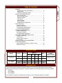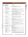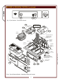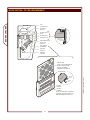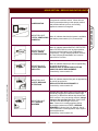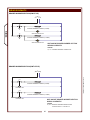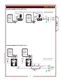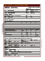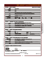
1
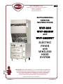
503
WELLS BLOOMFIELD, LLC
2 ERIK CIRCLE, P. O. Box 280 Verdi, NV 89439
telephone: 775-689-5707
fax: 775-689-5976
www.wellsbloomfield.com
SUPPLEMENTAL
SERVICE
INSTRUCTIONS
WVF-886
WVF-886RW
and
WVF-886RWT
ELECTRIC
FRYER
with
VENTLESS
HOOD
SYSTEM
IMPORTANT: WELLS BLOOMFIELD, LLC PROPRIETARY INFORMATION.
DISSEMINATION OF THIS INFORMATION TO ANYONE OTHER THAN
WELLS AUTHORIZED SERVICE AGENTS IS STRICTLY PROHIBITED.
TECHNICAL CONTENT OF THIS MANUAL IS DESIGNED FOR
USE BY QUALIFIED PROFESSIONAL TECHNICIANS ONLY.
PRINTED IN UNITED STATES OF AMERICA
p/n SV503 Rev.(-)
S503
080516
cps
PRECAUTIONS AND GENERAL INFORMATION
GENERAL
WARNING:
RISK OF
INJURY
Installation procedures must
be performed by a qualified
technician with full knowledge
of all applicable electrical and
plumbing codes. Failure can
result in personal injury and
property damage.
WARNING:
ELECTRIC
SHOCK HAZARD
All servicing requiring access
to non-insulated electrical
components must be
performed by a qualified
technician.
Some procedures involve
exposed live circuits. Use all
due caution to avoid contact
with live electric circuits.
Failure to follow this warning
can result in severe electrical
shock.
WARNING
SLIP / FALL
HAZARD
SPILLED OIL
This appliance is intended to prepare food for human consumption.
No other use is recommended or authorized by the manufacturer or its
agents.
Operators of this appliance must be familiar with the appliance use,
limitations and associated restrictions. Operating instructions must be
read and understood by all persons using or installing this appliance.
Cleanliness of this appliance is essential to good sanitation. Read and
follow all included cleaning instructions and schedules to ensure the
safety of the food product.
Disconnect this appliance from electrical power before performing any
maintenance or servicing.
DO NOT splash or pour water on, in or over any controls, control
panel or wiring.
The technical content of this manual, including any wiring diagrams,
schematics, parts breakdown illustrations and/or adjustment
procedures, is intended for use by qualified technical personnel.
Any procedure which requires the use of tools must be performed by a
qualified technician. All service to the fire suppression system must be
performed by an authorized Ansul® agency.
This appliance is made in the USA. Unless otherwise noted, this
appliance has American sizes on all hardware.
IMPORTANT INSTALLATION NOTE:
6” clearance is required from back and sides of the appliance to any
combustible or non-combustible surface.
This installation requires a minimum ceiling height of 96" in order to
maintain adequate airflow.
SV503 SvcManual WVF-886(RW)
DO NOT OPERATE UNLESS
THE GREASE CUP AND
TROUGH ARE INSTALLED.
Oil and moisture will drip onto
the floor and falls may result.
Death or serious injury may
result from slipping and falling
This appliance is intended for use in commercial establishments
only.
CAUTION:
RISK OF
DAMAGE
DO NOT connect or energize
this appliance until all
installation instructions are
read and followed. Damage to
the appliance will result if
these instructions are not
followed.
xi
TABLE OF CONTENTS
GENERAL
GENERAL
Precautions & General Information …………….………… xi
Specifications ..……………………………...................….. 1
Features & Operating Controls ……………………………. 2
VENTILATOR HOOD SECTION
Filter Arrangement .......................................................... 6
Service Indicator Lights .…….......................................… 7
Operational Notes ........................................................... 8
Filter System ................................................................... 10
Vacuum System .............................................................. 11
Ansul® System ............................................................... 12
Troubleshooting Suggestions ……………………………… 14
FRYER SECTION
Periodic Cleaning ............................................................. 16
Disposal of Used Oil ......................................................... 17
Fryhead Repair & Maintenance ........................................ 18
Troubleshooting Suggestions ........................................... 21
DRAWER WARMER SECTION
General Arrangement ...................................................... 22
RWT-Style Controller ........................................................ 23
Troubleshooting Suggestions ........................................... 24
EXPLODED VIEWS AND PARTS LISTS
Ansul® Components ......................................................... 25
Hood Section .................................................................... 26
Drawer Warmer Section ................................................... 28
Fryer Section .................................................................... 29
WIRING SCHEMATICS and DIAGRAMS .............................. 32
OTHER DOCUMENTS
Material Safety Data Sheet—Ansulex Low pH ................. 38
Maintenance Logs ............................................................ 40
SV503 SvcManual WVF-886(RW)
SPECIFICATIONS
MODEL
WVF-886
WVF-886RW
WVF-886RWT
VOLTS
WATTS
208
AMPS 3ø
AMPS 1ø
L1
L2
L3
N
12000
33
32
33
-
58
240
12000
29
28
29
-
50
208
12720
37
32
37
-
61
240
12900
29
28
29
-
54
POWER
SUPPLY CORD
NEMA 15-60P
NEMA 15-60P
INTRODUCTION
This manual contains information needed to properly service and repair Wells Bloomfield free-standing
electric fryer with ventless hood system. This manual applies to the following Wells Manufacturing models:
WVF-886
WVF-886RW
WVF-886RWT
For installation, operation and maintenance instructions, refer to Operation Manual p/n 304989.
1
FEATURES & OPERATING CONTROLS
28
VENTILATOR CONTROL PANEL
see pages 4 & 5
VENTILATOR
POWER ON
CHECK FILTERS
REPLACE
PREFILTER
a15
28
1
56
SERVICE
REQUIRED
REPLACE
FILTER PACK
53
VCS 2000
VENTLESS COOKING SYSTEM
19
16
FRYER CONTROL PANEL
see pages 4 & 5
a11
18
16
18
23
23
22
PUSH
ANSUL
40
12
IN CASE OF
FIRE
PUSH
a10
®
PULL
HANDLE
41
TO ACTIVATE
FIRE SUPPRESSION
SYSTEM
44
a6
LO
HI
7
2
3
8
WELLS
COCKED
OPTIONAL FRYPOT
DRAIN AND VALVE
see page 4 & 5
OFF
6
5
4
FIRED
a31
43
42
OFF
3
7
5
4
WARMER CONTROLS
see pages 4 & 5
8
2
LO
HI
WELLS
6
GENERAL
28
8
9
38
38
Fig. 1 Ventilator Section Operating Features & Controls
V2
V3
V4
Fig. 2 Ventilator Section - Controls & Indicator Lights
2
V5
V6
SV503 SvcManual WVF-886(RW)
V1
FEATURES & OPERATING CONTROLS (continued)
ITEM
DESCRIPTION
VENTILATOR SECTION
Lists Manufacturer, Model and Serial Number information.
Also lists electrical specifications.
a6.
FIRE SUPPRESSION
TANK (1.5 gal.)
8.
ADJUSTABLE (FRONT) LEG
Allows the unit to be leveled.
9.
RIGID (REAR) CASTER
Allows the unit to be easily positioned by lifting the front of the unit slightly.
a10.
MANUAL PULL STATION
Provides a means of manual activation of the fire suppression system.
PULL ONLY IN CASE OF FIRE!
a11.
FUSIBLE LINKS
Automatically activates fire suppression system in the event of fire in the fryer.
LOWER REAR ACCESS PANEL
Allows access to Ansul® fire suppression agent tank (a6) and controls also
access to main power contactor (41).
12.
a15.
AGENT
Container for Ansulex™ Low-pH liquid fire suppression liquid.
DISCHARGE NOZZLE
Fire suppression media discharges here (2 places).
16.
GREASE BAFFLE
Extracts and drains most grease and moisture from the air flow.
18.
PRE-FILTER ASSEMBLY
Comprises the PRE-FILTER FRAME and a replaceable
PRE-FILTER. Stops larger particles of grease from reaching the
PACK for reduced maintenance costs.
FILTER
19.
HEPA/CHARCOAL FILTER PACK
Stops most grease and smoke particles. Also assists in some cooking odor
removal.
22.
GREASE CUP
Collects grease/moisture drained from grease trough (23).
23.
GREASE TROUGH
Directs grease/moisture removed by grease baffle to grease cup.
28.
VENTILATOR EXHAUST DUCT
Exit point for ventilator airflow - on top left rear of unit.
DO NOT BLOCK
STATUS INDICATOR
Displays status of fire suppression system (COCKED - FIRED). If FIRED, a
buzzer will sound continuously.
38.
POWER CORD (WHEN PROVIDED)
6’ cord and cap. Plug for NEMA 15-60R (receptacle by user).
40.
WARMER RELAY
Provides power to roll warmer section. Energized at all times except during fire
safety shut-down.
41.
POWER CONTACTOR
Energizes fryer only while ventilator section is sensed as operational.
42.
BUILDING FIRE ALARM RELAY
Reports fire alarm condition to building fire management system.
43.
GROUND LUG
Ground wire of power cord connects here.
44.
INTERLOCK TERMINAL
Provides connection for shut-down control by building fire management system.
53.
FILTER INTERLOCK SWITCHES
Proper installation of grease baffle and filter pack close these switches in
ventilator sensor circuit.
56.
VENTILATOR FAN
Provides air movement for ventilation.
a31.
SV503 SvcManual WVF-886(RW)
NAMEPLATE
GENERAL
1.
COMMENT
VENTILATOR CONTROL AND INDICATOR PANEL
V1
POWER SWITCH
Energizes blower motor. If, after 10 seconds, proper conditions are met,
appliance is energized.
V2
POWER ON INDICATOR
GREEN. Glows when POWER switch is ON.
V3
CHECK FILTERS ALARM
INDICATOR
AMBER. Glows if one or more filters are out of position. Check all filters and
baffles for proper installation.
V4*
REPLACE PREFILTER ALARM
INDICATOR
AMBER. Glows when PREFILTER is approaching the end of its service life and
must soon be replaced.
V5*
REPLACE FILTER PACK ALARM
INDICATOR
AMBER. Glows when FILTER PACK is approaching the end of its service life
and must soon be replaced.
V6*
SERVICE REQUIRED ALARM
INDICATOR
RED. Glows when PREFILTER and/or FILTER PACK has reached the end of
its service life and is too loaded to allow sufficient air flow. Filter MUST be
replaced. Appliance is SHUT DOWN until expended filters are replaced.
3
FEATURES & OPERATING CONTROLS (continued)
GENERAL
F.02
F.01
F.02
Fig. 3 Fryer Section - Front Panel Controls
F.04
ELEMENT HEAD
(SHOWN LOWERED)
F.05
F.06
F.07
FRYER
BASKET
HEATING ELEMENTS
(ELEMENT HEAD
SHOWN RAISED)
BASKET LIFT
ELEMENT
LIFTING
HANDLE
FRYPOT
FRYPOT
HANDLES
ELEMENT
HEAD
SUPPORT
ROD
HUMI TROL
RACK
FUSE
FUSE
HOLDER
!
RW-STYLE
CAUTION:
Electric Sho ck Hazard
Disconn ect power b efor e
removing fu ses.
W.03
F.08
W.02
W.04
F.01
W.01
RWT-STYLE
W.06
W.05
Fig. 4 Fryer & Drawer Warmer - Operating Features & Controls
4
F.02
FRYPOT DRAIN
(OPTIONAL)
SV503 SvcManual WVF-886(RW)
DRAWER
INSERT PAN
ITEM
DESCRIPTION
COMMENT
FRYER SECTION CONTROLS
F.01
POWER SWITCH
Turns fryer section ON or OFF.
F.02
TIMER
Set to desired time, press to lower basket and begin timed cook cycle.
F.04
TEMPERATURE CONTROL
THERMOSTAT
Set to desired cooking temperature.
F.05
HEAT INDICATOR
AMBER. Glows when heating element is energized.
F.06
TROUBLE INDICATOR
RED. Glows if safety thermostat is tripped.
F.07
HI-LIMIT RESET
Allows hi-limit safety thermostat to be reset after oil has cooled below
400ºF.
F.08
DRAIN VALVE
Optional frypot drain. Valve is 1/4-turn ball valve.
NOTE: Drain not available on RW (roll warmer ) units
OPTIONAL DRAWER WARMER SECTION CONTROLS
RW-STYLE
W.01
WARMER TEMPERATURE
CONTROL
Infinite switch control of one warmer drawer.
W.02
POWER ON INDICATOR
AMBER. Glows when associated control is turned ON.
W.03
THERMOMETER
(OPTIONAL )
Shows temperature in warmer drawer. Must be ordered at time of
initial equipment build.
W.04
HUMIDITY CONTROL
Slide control of shutters to control air circulation within the warmer
drawer.
SV503 SvcManual WVF-886(RW)
RWT-STYLE
W.05
CONTROL MODULE
Adjust setpoint, view setpoint and actual temperatures.
W.06
WARMER POWER SWITCH
Energize individual drawer warmer.
5
GENERAL
FEATURES & OPERATING CONTROLS (continued)
HOOD SECTION - FILTER ARRANGEMENT
FAN
WALL OF UNIT
FILTER PA CK
SE AL
FILTER PACK
FILTER PA CK
AIR FLOW
VENTILATOR HOOD
FILTER PA CK
PO SITIO N
SWITCH
HOL DE R CLIP
GRE ASE B AFFLE
PO SITIO N
SWITCH
H OLDER CLIP
CLIPS ONTO
LEDGE
PRE -FILTER
AS SEMB LY
GRE ASE
BA FFL E
GRE ASE
TROUGH
PRE -FILTER
NOTE: AIR FL OW A RRO W
PO INTS AWAY FROM
INSTAL LER WHEN
PRO PERLY INSTA LLE D
FILTER HOOK
R
E
TE
R
FILTER
HOOK
FILTER
RAIL
FILTER
HANDLE
FILTER
FRAME
NOTE: P RE-FILTER IS S ENSE D
AS B EING IN POS ITION BY THE
PRE SSURE DROP A CRO SS IT.
6
SV503 SvcManual WVF-886(RW)
P
IL
-F
HOOD SECTION - SERVICE INDICATOR LIGHTS
POWER SWITCH
SV503 SvcManual WVF-886(RW)
INDICATOR LIGHT
When lit, indicates that electrical power is available,
(GREEN) VENTILATOR
and that the power switch (V.01) is turned ON.
POWER ON
INDICATOR LIGHT
(AMBER) CHECK
FILTERS (POSITION)
When lit, indicates that the BAFFLE, PRE-FILTER
and/or FILTER PACK is not in its proper position,
or that an interlock switch is out of adjustment.
Controlled by: Plunger switches position monitors
for Filter Pack and Grease Baffle; and, vacuum
switch S3 for Pre-Filter.
INDICATOR LIGHT
(AMBER) REPLACE
PREFILTER
When lit, indicates that the pre-filter is approaching
the end of its service life.
ALWAYS HAVE A SPARE PRE-FILTER ON
HAND FOR QUICK REPLACEMENT.
Controlled by vacuum switch S1.
INDICATOR LIGHT
(AMBER) REPLACE
FILTER PACK
When lit, indicates that the filter pack is approaching
the end of its service life.
REPLACE FILTER PACK PROMPTLY!
Controlled by vacuum switch S2.
INDICATOR LIGHT
(RED) SERVICE
REQUIRED
Indicates that either the pre-filter or the filter pack is
individually clogged (the individual indicator light
may be lit), or that the the airflow drop across both
filters is critical. As a cost saving measure, always
change a dirty pre-filter first (when lights V.04 &
V.05 are not lit, and red light V.06 is on).
Note: Power to the cooking appliance will be
de-energized whenever this RED “SERVICE
REQUIRED” indicator light is lit. When lit, the air
flow is insufficient to meet appliance vapor capture
levels requirements.
Controlled by vacuum switch S4.
7
VENTILATOR HOOD
Energizes the ventilator section. When all three
filters are sensed as being in their proper position,
and sufficient airflow is proven, the cooking
appliance contactor is energized.
HOOD SECTION - OPERATIONAL NOTES
WARNING:
FIRE AND HEALTH
HAZARDS
VENTILATOR HOOD
DO NOT bypass or attempt to
bypass the filter placement
interlocks. Operating the
appliance without filters properly
in place will compromise the fire
protection and air filtration
capabilities of this unit.
Serious personal injury and/or
substantial property damage may
result.
NOTICE:
Operating without all filters
properly in place, and/or
operating with filter placement
interlocks defeated will void the
manufacturer’s warranty.
IMPORTANT:
NEVER wash the PREFILTER or
FILTER PACK.This will shut
down the cooking appliance.
(Red “SERVICE REQUIRED”
light will turn ON).
REPLACE PREFILTER and REPLACE FILTER PACK indicator lights
provide a timely warning that a system shut-down is imminent. The
actual time between the indicator light coming on and the loss of
cooking appliance power will depend upon the cooking conditions.
Anytime a dirty PRE-FILTER is replaced, the system airflow will
increase. If the condition of the FILTER PACK is marginal, the
REPLACE FILTER PACK light could then come on. If this happens, a
fresh FILTER PACK must be installed within a reasonably short time.
Loss of airflow through the old filter pack will soon cause a system
shut-down when the airflow falls below minimum vapor capture levels.
KEEP SPARE FILTER PACKS ON HAND.
IMPORTANT: If you decide to “get the most” out of the old filter pack,
and continue to use it until a system shut-down happens, it is advisable
to have a fresh filter pack readily at hand, and have someone available
who is capable of replacing it. Otherwise, you may experience an
extended down time, with consequent associated loss of business.
The manufacturer assumes no liability for loss of business due to
a system shutdown caused by a dirty pre-filter and/or filter pack
(i.e. red SERVICE REQUIRED light is on), when the user fails to
have the proper replacement pre-filter and/or filter pack on hand.
SV503 SvcManual WVF-886(RW)
8
HOOD SECTION - OPERATIONAL NOTES (continued)
FIRE
DAMPER
LABEL
SHUTTER
DAMPER
SUPPORT
FUSIBLE LINK
280ºF
FIRE DAMPER INSTRUCTIONS
1. The FIRE DAMPER is accessible by removing the TOP PANEL
The FIRE DAMPER sets in the DAMPER SUPPORT and may be
removed by lifting straight up.
SV503 SvcManual WVF-886(RW)
2. The FIRE DAMPER normally needs no maintenance. If it
becomes heavily contaminated with dust and/or grease, it must
be replaced.
3. If the FIRE DAMPER malfunctions or if the fusible link releases,
the manufacturer recommends that the entire FIRE DAMPER
ASSEMBLY be replaced.
4. Reinstall the FIRE DAMPER with the “THIS SIDE UP FOR
HORIZONTAL MOUNTING” arrow pointing away from the
BLOWER.
9
IMPORTANT:
Replace the entire fire damper
assembly if the link trips, or if the
damper mechanism becomes
heavily contaminated with dust
and/or grease.
While the fusible link alone may be
replaced, once the damper has
tripped it may no longer function
reliably.
Contact factory for pricing and
availability.
VENTILATOR HOOD
THIS SIDE UP
FOR HORIZONTAL
MOUNTING
THIS
SIDE UP
FOR VERTICAL
MOUNTING
¬ ®
AIR FLOW
ACCESS DOOR
THIS SIDE
HOOD SECTION - FILTER SYSTEM
HOOD ASSEMBLY
(LOOKING UP)
VENTILATOR HOOD
FILTER PACK
POSITION MONITOR
GREASE BAFFLE
POSITION MONITOR
PRE-FILTER
ASSEMBLY
NOTE AIR FLOW ARROWS ON
GREASE BAFFLE, PRE-FILTER
AND FILTER PACK. INSTALL
THESE COMPONENTS SUCH
THAT ARROWS POINT
TOWARD FAN
FILTER
PACK
GREASE
BAFFLE
1. The GREASE BAFFLE separates grease particles and water vapor
from the air stream by the centrifugal force of the air moving through
its inter-leaved baffle plates. Ejecta is collected in the GREASE CUP
through drain holes in the baffle frame and cabinet.
The GREASE BAFFLE POSITION MONITOR plunger switch controls
electric power to the ventilator fan.
NOTE:
The charcoal portion of the
filter pack is an aid in
controlling cooking odors
only. It will not completely
eliminate such odors.
2. The PRE-FILTER is composed of a replaceable media filter and a
filter-retaining gage. The pre-filter captures the bulk of grease vapors.
Pre-filter position is monitored by a vacuum switch, which is in the
control circuit of the cooking appliance contactor.
3. The FILTER PACK is composed of a high-efficiency filter to capture
grease vapors down to a very small particle size; and, an activated
charcoal filter to help control cooking odors.
The FILTER PACK POSITION MONITOR plunger switch is in the
control circuit of the cooking appliance contactor.
10
SV503 SvcManual WVF-886(RW)
NOTE:
Change the pre-filter as
soon as the "REPLACE
PRE-FILTER" indicator
glows in order to extend the
service life of the filter pack.
HOOD SECTION - VACUUM SYSTEM
FAN
PORT A
VS4
PORT A
VS1
VENTILATOR HOOD
PORT B
FAN
PORT C
PORT C
PORT C
VS3
PORT B
PLENUM PORT
(AFTER FILTER PACK)
VS2
SV503 SvcManual WVF-886(RW)
VS2
FILTER PACK ALERT
Will illuminate "REPLACE FILTER PACK"
indicator if pressure drop across the filter
pack exceeds setting.
VS3
PRE-FILTER ALERT
Will illuminate "REPLACE PRE-FILTER"
indicator if pressure drop across the prefilter exceeds setting.
VS4
AIR FLOW MONITOR
Pressure drop must exceed setting before
cooking appliance is energized. As filters
become plugged, airflow decreases.
Beyond the useful life of the filters, air flow
will be insufficient to maintain the required
pressure drop, which will shut-down
ventilator fan and cooking appliance and
illuminate "SERVICE REQUIRED"
indicator.
GREASE
BAFFLE
PREFILTER
SWITCH
VS1
PRESSURE
RISE FROM
FAN
PRESSURE
DROP ACROSS
FILTER PACK
PRE-FILTER POSITION MONITOR
Unit will not function unless a pre-filter
is properly installed, as sensed by the
pressure drop across it. Pressure drop
across the pre-filter must exceed setting
before cooking appliance is energized.
Insufficient pressure drop will illuminate
"CHECK FILTER" indicator.
AMBIENT
PRESSURE
VS1
PRESSURE
DROP ACROSS
BAFFLE
SWITCH FUNCTION
PRESSURE
DROP ACROSS
PRE-FILTER
CABINET PORT
(BEFORE FILTER PACK)
FILTER
PACK
FAN
SWITCH
VS2
SWITCH
VS4
AIR FLOW
SWITCH
VS3
IMPORTANT:
Vacuum switch settings are factory set, and are not
adjustable.
11
HOOD SECTION - ANSUL® FIRE DETECTION SYSTEM
HOO D ASS EMBLY
VIEWED FROM R EAR
SER IES
DETEC TOR
VENTILATOR HOOD
FU SE LINK
165 ºF
FU SE LINK
165 ºF
IN
CA
FI
BLIND
HOLE
H
ANS
UL
SE
RE OF
PU
A LL
N
DL
E
MANUAL
PU LL STAT ION
THREADED
THRU HOLE
CABLE SITS IN
GROOVE IN
PU LLEY
PULLEY
ELBOW
IMPORTANT:
All servicing of the fire
detection system to be
performed by an
authorized Ansul® agent
only.
1. Cooking appliance protected by two series detectors with 165ºF
fusible links.
2. Fire suppression system may be activated by the manual pull station
on the front of the unit, or by a remote manual pull station if installed.
3. A microswitch in the Ansul® Automan assembly allows connection to
a building fire alarm system.
12
SV503 SvcManual WVF-886(RW)
MIC ROSWITC H
HOOD SECTION - ANSUL® FIRE SUPPRESSION SYSTEM
HOOD ASSEMBLY
VIEWED FROM REAR
FLEX
HOSE
NOZ ZLE 1W
PLENUM
NOZZLE ASSY
NOZ ZLE 1W
APPLY SEALANT TAPE
SEAL WITH
TEFLON TAPE
IN S
ID
E
OU
TS
I DE
FIBER
WASHER
IS ALWAYS
ON THE INSIDE
CABINET WALL
SEAL WITH
TEFLON TAPE
SV503 SvcManual WVF-886(RW)
TYPICAL BULKHEAD
FITTING
FIRE SUPPRESSION
MEDIA TANK
PRESSURE
CARTRIDGE
1. Actuation of the Ansul® system will cause the pressure cartridge seal
to be punctured, which will pressurize the 1.5 gallon media tank. Fire
suppression media will be forced through the piping where it will spray
from the various nozzles.
2. The cooking appliance surface is protected by a type 1W nozzle.
3. The plenum area between the filters and the fan is protected by a
single type 1W nozzle.
4. The pressure integrity of the plenum bulkheads is maintained by the
use of compression fittings at the piping penetrations.
5. Nozzles are protected from grease contamination by press-on silicone
rubber caps.
13
IMPORTANT:
All servicing of the fire
suppression system to be
performed by an
authorized Ansul® agent
only.
VENTILATOR HOOD
UNDER-HOOD
NOZZLE
ASSY
HOOD SECTION - TROUBLESHOOTING SUGGESTIONS
SYMPTOM
VENTILATOR HOOD
Entire unit inoperative
No lights glow
No buzzer sounds
Cooking appliance inoperative
“POWER” light on hood ON. Vent
fan working ok with no service
Cooking appliance inoperative
“POWER” light on hood ON.
Vent fan working OK.
"SERVICE REQUIRED" light ON
SUGGESTED REMEDY
Unit unplugged.
Plug power cord into receptacle
Circuit breaker off or tripped
Reset circuit breaker
Damaged power cord
Replace power cord
Damaged power switch
Check switch. Replace as req’d.
External interlock jumper loose or
damaged (unit is not connected to
building fire control system)
Check jumper. Repair or replace
as required
External interlock open (unit
connected to building fire control
system)
Locate and rectify open circuit
condition in building fire control
system.
Contactor, wiring or connectors
damaged
Replace contactor
Repair wiring
Vacuum line to switch VS4
restricted
Check for restriction in vacuum
line to switch.
Vacuum switch VS4 open or
defective
Check vacuum switch VS4.
Replace as req’d.
Vacuum pickup port in plenum, or
vacuum port on blower plugged
Clean vacuum ports
NOTE: Vacuum port in plenum
may appear as a place to attach
a nozzle. Do not attach a nozzle
here. It will block the vacuum
signal (see pg 11).
Fire damper tripped
Replace fire damper
NOTE: While the fusible link alone
may be replaced, once the
damper has tripped it may no
longer function reliably.
Grease baffle and/or filter pack
position switch(es) open
Missing or un-seated filter assy.
Reseat filter or adjust interlock
switch.
Vacuum switch VS1 open or
damaged
Be sure pre-filter is hooked in
position. Check for damaged
vacuum line, or one that is
disconnected at the vacuum
switch or pick-up port. Also check
port for grease contamination.
14
SV503 SvcManual WVF-886(RW)
Vent fan working OK, but amber
“CHECK FILTERS” light stays ON
POSSIBLE CAUSE
HOOD SECTION - TROUBLESHOOTING SUGGESTIONS (continued)
POSSIBLE CAUSE
Prefilter is at end of service life
Vent fan working OK, but amber
“REPLACE PREFILTER” light ON. Vacuum Switch VS3 damaged
“REPLACE PREFILTER” light
turns on some of the time.
“REPLACE FILTER PACK” light
ON.
Replace prefilter
Replace vacuum switch VS3
Pre-filter frame not hooked in
position at top
Hook metal pre-filterframe at top
to prevent air blowing around filter
Pre-filter position switch SW1
misadjusted or damaged.
Check switch SW1, adjust or
replace
Prefilter is nearing end of service
life
Replace prefilter
Filter pack nearing end of its
service life
Replace filter pack
Filter pack vacuum switch VS2
Check switch VS2, repair vacuum
lines restricted or switch damaged. lines or replace switch.
Appliance newly installed and
Ansul® system not yet charged.
Vent fan not operating and buzzer
is sounding.
SUGGESTED REMEDY
Check status of Ansul® system at
rear of unit, if fired, call Ansul®
Service Distributor for set-up.
Check status of Ansul® system at
rear of unit, if fired, call Ansul®
Service Distributor for
Ansul® system has been set off by
replacement of fire suppression
overtemp condition, or manual pull
agent and propellant. If fuse link
station has been activated.
has been activated, it must be
replaced prior to re-cocking the
Ansul® system.
SV503 SvcManual WVF-886(RW)
Vent fan not operating.
Grease baffle not installed
Install grease baffle.
Buzzer silent.
Green “POWER” light ON.
Amber “CHECK FILTER” light and Grease baffle position switch SW2 Check switch SW2, adjust or
misadjusted or damaged.
replace
red “SERVICE REQUIRED” light
ON.
15
VENTILATOR HOOD
SYMPTOM
FRYER SECTION - PERIODIC CLEANING
CAUTION:
PERIODIC CLEANING
BURN HAZARD
Add 1/2 cup of granulated dishwasher detergent to frypot. Fill with water
to the MAX OIL line.
Be sure frypot and
elements are dry before
returning unit to service.
Water left in the frypot will
boil off when heating,
splattering hot oil.
Lower the element into the frypot and set the control knob to 225ºF
Boil the mixture for five minutes. Turn the control knob to OFF. Allow the
mixture to set in the frypot overnight.
After the soak period, raise the elements and remove any remaining
carbonization with a stiff bristle brush. Be careful that the capillary tubes
of the thermobulbs are not moved or damaged during cleaning.
CAUTION:
Drain the frypot and wash with warm water and mild detergent.
BURN HAZARD
Reinstall the frypot in the fryer. Add 1 quart of vinegar, then fill to the MAX
OIL line with cold water.
Before cleaning, ALWAYS:
• Disconnect fryer from
electric power and allow
to cool.
• Drain the oil and wipe
out the frypot.
Lower the elements into the vinegar solution. Allow to set for 15 minutes.
Drain the frypot and rinse with clean water. Dry the frypot and elements
thoroughly before returning the fryer to operation.
IMPORTANT: Nickel plated frypot must be dried completely in order to
prevent rusting, and to eliminate water contamination of the cooking oil.
FRYER
Periodic cleaning is
necessary to remove
carbonization from the
elements and frypot.
Frypot may be cleaned by
the method described at
right, or with a commercial
frypot cleaner. Be sure to
follow the manufacturer's
directions.
SV503 SvcManual WVF-886(RW)
16
FRYER SECTION - DISPOSAL OF USED OIL
DANGER: BURN HAZARD
Contact with hot oil will cause severe burns. Allow the fryer to cool before cleaning.
Always wear protective clothing and heat resistant gloves when handling hot oil.
PREPARATION Turn temperature control to OFF
Allow fryer to cool completely before draining
FREQUENCY
Daily, or as needed
TOOLS
Container for disposal of used oil.
OIL DISPOSAL
CAUTION:
BURN HAZARD
Allow fryer to cool completely
before draining.
CAUTION:
2. Allow the oil to cool to a safe temperature (120ºF or 50ºC).
3. Raise the element head and lift the frypot out of the fryer by the
frypot handles.
4. Dispose of the used oil in an approved oil disposal receptacle, or
filter the oil for reuse.
SLIP AND FALL
HAZARD
Clean up oil spills
immediately. Slipping in oil
can cause injury.
CAUTION:
5. Wipe the frypot and reinstall in the fryer.
HEALTH
HAZARD
Procedure is complete.
SV503 SvcManual WVF-886(RW)
Clean up oil spills
immediately. Oil provides an
environment for the growth of
bacteria, which presents a
health hazard.
17
FRYER
1. Turn temperature control to OFF.
FRYER SECTION - REPLACE HEATING ELEMENT
5/8-18 NUT
LOCK WASHER
FIBER WASHER
CAUTION:
BURN HAZARD
CAPILLARY CLIP
6 places
Allow fryer to cool before
performing this service.
ELEMENT
BULB CLIP
4 places
CAUTION:
SHOCK HAZARD
2 places
HI-LIMIT
BULB (ref)
Element Assembly
Disconnect fryer from electric
power before servicing.
IMPORTANT:
DO NOT damage the
capillary tubes. If the tubes
are pinched or kinked, they
are not repairable.
5/8-18 NUT
LOCK WASHER
CONTROL BOX
FIBER WASHER
ELEMENT
FRYER
Element Attachment
CAPILLARY CLIP
BULB CLIP
BULBS (ref)
ELEMENT
Cross-Section View of
Element and Thermobulbs
IMPORTANT: Disconnect from electric power and allow fryer to cool
before servicing.
A. REMOVE ELEMENT HEAD FROM FRYER
Note: Some operations can be performed without removing the
fryhead. However, doing so will ease access to components and
fasteners.
1. Remove two screws holding either element head pivot.
Remove pivot.
2. Lift element head assembly from fryer.
3. Remove bottom cover from control box.
B. DISCONNECT ELEMENT
1. Disconnect the wiring from the element terminals.
2. Note position of each thermobulb and the routing of the capillary
tubes. Remove bulbs from element by removing two bulb clips and
three capillary clips from each bulb.
3. Undo both holding nuts from terminal end of the element.
4. Withdraw the element from the control box.
C. INSTALL NEW ELEMENT
1. Wipe area around element openings in control box to remove any
grease or other cooking debris.
2. Slide one fiber washer over each end of the new element.
3. Insert element into the control box. Slide a lock washer over each
element, then thread on the holding nuts. Make sure the element
is square with the control box. Tighten holding nuts.
4. Reconnect wiring to the element terminals.
5. Reinstall the thermobulbs. Be sure a bulb clip is in place at each
end of the thermobulb.
NOTE: Control and HI-Limit thermobulbs may require different
bulb clips. Refer to parts list for proper component.
Snap a bulb clip over the element to secure the bulb. Carefully
route the capillary tube and secure with three capillary clips.
Repeat for both bulbs.
D. REINSTALL ELEMENT HEAD ON FRYER
1. For F-49, be sure the pivot washer is in place on the pivot brackets.
While holding the support rod in the forward position, slide the
element head assembly onto the fixed pivot. Reinstall the pivot
removed In step A.
Test fryer for proper operation and return to service.
18
SV503 SvcManual WVF-886(RW)
IMPORTANT:
Be sure thermobulbs are
correctly seated in bulb clips.
These clips hold the bulbs
away from the element
surface. Failure to properly
position the clips will result in
the immediate failure of the
thermostat due to thermobulb
damage.
TEMP
CONTROL
BULB (ref)
FRYER SECTION - REPLACE CONTROL OR HI-LIMIT THERMOSTAT
HI-LIMIT
THERMOSTAT
CONTROL
KNOB
CAUTION:
BURN HAZARD
Allow fryer to cool before
performing this service.
Thermostat
Installation
TEMP
CONTROL
THERMOSTAT
CAUTION:
SHOCK HAZARD
CAPILLARY CLIP
6 places
Disconnect fryer from electric
power before servicing.
BULB CLIP
4 places
TEMP CONTROL
THERMOSTAT BULB
IMPORTANT: Disconnect from electric power and allow fryer to cool
before servicing.
A. REMOVE ELEMENT HEAD FROM FRYER
Note: Some operations can be performed without removing the
fryhead. However, doing so will ease access to components and
fasteners.
1. Remove two screws holding either element head pivot.
Remove pivot.
2. Lift element head assembly from fryer.
3. Remove bottom cover from control box.
SV503 SvcManual WVF-886(RW)
B. DISCONNECT THERMOSTAT
1. Remove the control knob if replacing the temperature control
thermostat.
2. Remove the two screws holding the thermostat to the control box.
3. Note the position of the wiring. Disconnect the wiring from the
thermostat terminals.
4. Note position of the thermobulb and the routing of the capillary
tube. Remove the bulb from the element by removing two bulb
clips and three capillary clips.
5. Undo the pass-thru fitting and withdraw the thermostat from the
control box.
C. INSTALL NEW THERMOSTAT
1. Wipe area around pass-thru openings in control box to remove any
grease or other cooking debris.
2. Undo nut and lock washer from pass-thru fitting of the new
element. Insert the bulb from the inside of the control box.
3. Reconnect wiring to the thermostat terminals. Connect wiring then
attach the thermostat to the control box
4. Reinstall the thermobulbs. Slide two bulb clips over the bulb,
spacing the clips 3/8" from each end of the bulb. Snap the bulb
clips over the element, centering the bulb between element bends.
Carefully route the capillary tube and secure with three
capillary clips.
5. Carefully route capillary tube away from electrical terminals
inside of the control box. Tighten the pass-thru fitting then seal the
inside of the pass-thru fitting with hi-temp sealant.
D. REINSTALL ELEMENT HEAD ON FRYER (see page 16)
Test fryer for proper operation and return to service.
19
IMPORTANT:
DO NOT damage the
capillary tubes. If the tubes
are pinched or kinked, they
are not repairable.
FRYER
HI-LIMIT THERMOBULB
Capillary Tube Pass-Thru
Fitting
IMPORTANT:
Be sure bulb clips are
properly positioned on bulb,
and are clipped to element to
maintain the gap between
bulb and element. Failure to
properly position the rings will
result in the immediate failure
of the thermostat due to
thermobulb damage.
3/8"
Bulb Clip Spacing
3/8"
FRYER SECTION - REPLACE SPRING FOR FRYHEAD SUPPORT ROD
CAUTION:
BURN HAZARD
Allow fryer to cool before
performing this service.
Support Rod
Spring Installation
CAUTION:
SHOCK HAZARD
Disconnect fryer from electric
power before servicing.
IMPORTANT: Disconnect from electric power and allow fryer to cool
before servicing.
A. REMOVE ELEMENT HEAD FROM FRYER
Note: Some operations can be performed without removing the
fryhead. However, doing so will ease access to components and
fasteners.
1. Remove two screws holding either element head pivot.
Remove pivot.
2. Lift element head assembly from fryer.
3. Remove bottom cover from control box.
FRYER
B. REMOVE BROKEN SPRING
1. Using a flat blade screwdriver or other suitable tool, pry the split
end of the support rod to open the slot.
2. Remove and discard the broken spring parts.
C. INSTALL NEW SPRING
1. Position the support rod toward the back (power cord) side of
the control box, then slide the new spring over the split end of
the support rod.
Note orientation: Long leg of spring at the top and pointing
toward the front; short leg of spring in the slot.
2. Using pliers, squeeze the split end of the support rod to capture
the spring.
3. Tension the spring by swinging the long leg clockwise, and
allowing it to rest against the lip of the control box.
Test fryer for proper operation and return to service.
Installation Sequence
20
SV503 SvcManual WVF-886(RW)
D. REINSTALL ELEMENT HEAD ON FRYER
1. While holding the support rod in the forward position, slide the
element head assembly onto the fixed pivot. Reinstall the
pivot removed In step A
FRYER SECTION - TROUBLESHOOTING SUGGESTIONS
POSSIBLE PROBLEM
Unit not plugged in or circuit breaker
tripped
Plug into proper receptacle
Reset circuit breaker
Ventilator not running
Press ventilator power switch ON
Cooking appliance contactor not
energized
Refer to hood section to troubleshoot
ventilator problems
Fryer power switch not ON
Press fryer heat switch ON
Damaged internal component
Check wiring and connections
Temperature control knob not set to
desired temperature
Set to desired temperature
Hi-limit safety tripped
Clean element, reset hi-limit
Damaged internal component
Check thermostat, hi-limit, element,
Check wiring and connections
Fryer will not maintain
temperature
Control thermostat thermobulb
contaminated with cooking debris
Clean element
Fryer leaks oil
Damaged frypot
Replace drain valve (if used)
Replace frypot
Fryer will not heat
(both sections)
Fryer will not heat
(one section)
Element head cannot be Frypot out of position, or has excess
raised
cooking debris in bottom
Check frypot for position
Clean frypot
Element head will not
stay in the up position
Damaged hinge bracket, support rod or
support rod spring
Replace damaged hinge
Replace support rod and/or spring
Support rod not moved from support
position
Lift head slightly, then swing support
rod fully forward
Damaged hinge bracket or support rod
Replace damaged hinge
Replace support rod
Fuse(s) blown
Correct cause and replace fuse(s)
Damaged internal component
Check timer, lift motor, microswitch
Check lift mechanism components
Check wiring and connections
Timer not set
Set to desired cook time
Timer "PUSH" button not pushed
Push to start
Damaged internal component
Check timer, lift motor, microswitch
Check lift mechanism components
Check wiring and connections
Lift shaft seal(s) contaminated with
grease
Clean or replace seals
Lift cam loose on motor shaft
Tighten lift cam set screw
Damaged internal component
Check timer, lift motor, microswitch
Check lift mechanism components
Check wiring and connections
Element head will not
lower to cooking position
Basket lift will not move
SV503 SvcManual WVF-886(RW)
SUGGESTED REMEDY
Basket lift will not lower
Basket lift will not raise
21
FRYER
DESCRIPTION
DRAWER WARMER SECTION - OPERATIONAL NOTES
OPTIONAL
HUMITROL
RACK
DRAWER
STOP
PRODUCT
PAN
LATCH
ASSEMBLY
OPTIONAL DIAL
THERMOMETER
DRAWER
ASSEMBLY
THERMOSTAT
CONTROL
KNOB
OPTIONAL ELECTRONIC CONTROL
CONTROL MODULE
POWER
SWITCH
ºF OR ºC
INDICATORS
LED READOUT
CONTROL
MODULE
"PROCESS" KEY
PROCESS
LOAD
INDICATOR
INCREMENT AND
DECREMENT KEYS
BURN HAZARD
Interior of drawer warmer cavity will
be hot during operation. Allow unit
to cool before performing any
service.
NOTE:
In the absence of a drawer warmer
appliance, the WVF-886 is
equipped with a storage cabinet in
the base. This single cabinet has
two doors.
1. The optional drawer warmer unit is a Wells RW-26HD or
RWT-26HD two-drawer roll warmer unit.
2. The drawer warmer has two individually controllable sections.
a. Control of RW-style unit is via bulb and capillary
thermostat with SPST switch.
b. Control of RWT-style unit is via electronic controller.
3. Each section is heated by a single element of roughly
rectangular configuration.
4. Drawer warmer is powered by the drawer warmer relay
5. Optional dial thermostat may be located on either or both
drawer sections.
6. Digital controller will replace thermometer-equipped units in
new production. Thermometer-equipped units are to become
obsolete.
22
SV503 SvcManual WVF-886(RW)
DRAWER WARMER
CAUTION:
DRAWER WARMER SECTION - CONTROL MODULE for RWT- STYLE UNITS
CONTROL MODULE
ITEM
1
2
3
DESCRIPTION
1
PROCESS Key:
Press to view actual temperature of cavity.
2
4 Character LED Display:
Normally shows SETPOINT temperature.
3
ºF or ºC Indicator:
Glows to indicate if unit is configured for
degrees Fahrenheit or degrees Celsius.
4
LOAD Indicator:
Glows when heating element is energized.
5
Increment and Decrement Keys:
Press UP arrow to increase
Press DOWN arrow to decrease
ºF
ºC
LOAD
PROCESS
4
5
SET SETPOINT TEMPERATURE
Press an arrow key:
UP arrow to increase
DOWN arrow to decrease
Release key when desired setpoint temperature
is displayed.
ºF
ºC
LOAD
Reading is locked into memory 3 seconds after
last key stroke.
PROCESS
DRAWER WARMER
SV503 SvcManual WVF-886(RW)
Minimum setpoint is 140ºF (60ºC)
Maximum setpoint is 250ºF (121ºC)
CHANGE DISPLAY MODE ( ºF or ºC)
Press and hold UP arrow and DOWN arrow keys
for 10 seconds.
ºF
Release keys when display reads F
LOAD
ºC
C.
Within 3 seconds, press UP arrow or DOWN arrow
key until desired indicator (ºF or ºC) glows.
PROCESS
The new value will lock into memory 3 seconds
after last keystroke.
HOLD
10 SEC.
23
DRAWER WARMER SECTION - TROUBLESHOOTING SUGGESTIONS
SYMPTOM
No lights or heat
(both drawers)
No heat (one drawer)
POSSIBLE CAUSE
SUGGESTED REMEDY
Hood power switch not "ON"
Press power switch to "ON"
NOTE: Drawer warmer is
energized any time hood power
switch is "ON" and Ansul® system
is ready. Hood need not be
operating.
Temperature control not set
Set for desired temperature.
Damaged thermostat or heating
element (RW-style units)
Inspect thermostat, heating
element, wiring and connections.
Repair/replace as necessary.
Inspect controller, temperature
Damaged controller or temperature
sensor, wiring and connections.
sensor (RWT-style units)
Repair/replace as necessary.
Runaway temperature
(one drawer)
Food dries out
Inspect cap tube for kinks or
breaks. Replace thermostat.
(RWT-style units)
Unlikely to fail "hot" due to
controller or sensor malfunction.
Inspect for shorted wiring.
Humidity control (air vent) not set
OPEN air vent for dry operation.
CLOSE air vent for moist
operation.
Water in pan evaporated or low
Add water to pan.
Food contacting water
Use a Humitrol Rack
Water level too high
Water should be no more than
1/2" deep
Humidity control (air vent) not set
OPEN air vent for dry operation.
CLOSE air vent for moist
operation.
Drawer latch catch roller not
extended before closing drawer
Be sure catch roller is extended
before installing drawer.
Drawer latch damaged
Replace drawer latch
Drawer stop dirty
Clean and lubricate drawer stop
Drawer stop damaged
Replace drawer stop
Food gets soggy
Drawer falls open
Drawer falls out when opened
24
SV503 SvcManual WVF-886(RW)
DRAWER WARMER
Damaged thermostat or thermobulb capillary tube (RW-style
units)
FOR USE ONLY BY AUTHORIZED
ANSUL© SERVICE PERSONNEL
ref. ADAPTER, QUICK-SEAL 3/8”
ANSUL© p/n 77284
Refer to Ansul© part no. 418078-05
R-102 Restaurant Fire Suppression
System Design, Installation,
Recharge and Maintenance
ref. NOZZLE 1W
ANSUL© p/n 419336
FUSIBLE LINK
165ºF 502583
ASSY, PULL STATION
ANSUL©
501389
F
TO
IT
UN
ON
FR
ref. MOUNTING BRACKET
RELEASE MECHANISM
R-102 ANSUL© p/n 79493
ref. PULLEY ELBOW
ANSUL© p/n 423250
(typical)
(NOT SHOWN)
MICROSWITCH 67273
TERM.BLOCK 53068
NIT
SV503 SvcManual WVF-886(RW)
ref. CABLE, WIRE ROPE
ANSUL© p/n 15821 (50’/15m)
79653 (500’/152m) (typical)
CK
BA
U
OF
ref. TANK 1.5 GAL, ANSULEX®
ANSUL© p/n 429864
(NOT SHOWN)
ANSULEX ® EXTINGUISHING
AGENT 1.5 GAL.
ANSUL© p/n 429864
CARTRIDGE LT-20-R
ANSUL© p/n 67099
insi
de
Seal with
Teflon tape
side
Fiber
washer
is always
on the inside
ANSUL© p/n 77284
DETAIL
Cable sits in
groove in
pulley
out
cabinet wall
ANSUL© p/n 423250
DETAIL
Seal with
Teflon tape
25
EXPLODED VIEWS
PARTS BREAKDOWN for ANSUL® COMPONENTS
HOOD CABINET COMPONENTS
EXPLODED VIEWS
INTERNAL BRACKETS
FIRE DAMPER ASSY
280ºF (ref. 301187)
LABEL, CONTROL
PANEL 502782
GASKET, SILICONE
15-1/4” 502772 (2 pl)
GASKET, SILICONE
18-1/2” 502773 (2 pl)
ASSY, FILTER
PACK 22619
PREFILTER
22618
HOUSING, LIGHT
SOCKET 505098
CAGE,
PRE-FILTER
22683
BULB, APPLIANCE
100W
505100
GLASS GLOBE, LIGHT
BULB COVER 505099
GREASE CUP
504405
BAFFLE, GREASE
FILTER (TYPE 3)
22684
MAGNET, DOOR
CATCH 66502 (2 pl)
ASSY, PULL STATION
ANSUL
501389
-RW UNITS
SET, CASTERS
20804
(2 swivel, 2 fixed)
CABINET DOORS
(NON -RW UNITS)
LEG, ADJUSTABLE
VCS 22649 (pk 2)
(REAR LEG OPTION)
ASSY, DOOR
RIGHT 502646
26
SV503 SvcManual WVF-886(RW)
ASSY, DOOR
LEFT 502642
FITTING, 1/2” CONDUIT
STRAIGHT 57748
EXPLODED VIEWS
HOOD ELECTRICAL & VACUUM COMPONENTS
ASSY, BLOWER
240V
502584
VACUUM SWITCH
#4
502593
VACUUM SWITCH
#1
502590
VACUUM SWITCH
#3
502592
ASSY, VAC TUBE
MANIFOLD 502588
VACUUM SWITCH
#2
502591
ref Ansul®
77284
ref Ansul®
77284
SWITCH, POWER
8528-40
SWITCH, FILTER
INTERLOCK
500407 (2 pl)
BUZZER, 240V
64834
LIGHT, INDICATOR
GREEN 240V 55697
LIGHT, INDICATOR
AMBER 240V 50516 (3 pl)
OD
P
LIGHT, INDICATOR
RED 240V 51157
FR
ON
TO
FH
L
D
A
IC
P
- U
R
CT
E
EL
OO
ER
HO
TERMINAL BLOCK
2P 250V 53068
JUMPER, FLAME
SENSOR 54005
SV503 SvcManual WVF-886(RW)
RELAY, 208/240V
(-RW, -RWT ONLY) 63880
HOUSING, LIGHT
SOCKET 505098
BULB, APPLIANCE
230V 100W 505100
CONTACTOR 208/240V
50A 3-PH 502789
STRAIN RELIEF
1-1/4” 504420
RELAY, BLDG
FIRE ALARM
64514
GLASS GLOBE
LIGHT BULB
COVER 505099
POWER CORD
NEMA 15-60P
22682
(incl. strain relief)
ELECTRICAL - REAR OF LOWER CABINET
ELECTRICAL - UNDER HOOD
27
DRAWER WARMER COMPONENTS
21488
55487 (pk 50)
part of 50471
18-302
55565
55530 (pk 10)
67096
heavy-duty
drawer assy
complete
55487
(pk 50)
69251
CLO
SED
50483 (pk 6)
OPE
N
51796
64475 OPTIONAL
THERMOMETER
52112
50471 (includes
strike and catch)
18-302 (typ.)
55677
55683
50482 (240V)
50519 (120V)
65923 (set includes left
and right)
65351 (CAVITY ASSEMBLY)
63271
(pk 10)
51801(UPPER)
53565 (LOWER)
SV503 SvcManual WVF-886(RW)
50483 (pk 6)
51808
55687
0
OFF
H
-RWT ELECTRONIC CONTROL
OPTION (PART NO. PENDING)
50372
58936
7
3
WELLS
8
2
LO
I
6
5
4
EXPLODED VIEWS
20624
(optional)
28
505656
50227
51179
55487
51718
(pk 50)
(pk 10)
4 places
52073
505658
ER
TI
M
52681
52667
50231
2 places
51145
(pk 6)
2 places
51146
51259
50233
51040
SV503 SvcManual WVF-886(RW)
50198
50543
50207
50205
51048
50222
4 places
(pk 10)
(pk 10)
4 places
50876
2 places
50850
50878
50215
29
EXPLODED VIEWS
FRYER AUTOLIFT COMPONENTS
FRYER FRYHEAD COMPONENTS
HEAD ASSY, COMPLETE, F-886
62926 (208V)
62927 (240V)
NOTE: Fryer has two identical
fryer heads. Only one is shown.
50177 fiber washer
50176 lock washer (pk 10)
57882
50172
55510
50516 amber
temp control
50157
51157 red
62504
(pk 4)
58656
hi-limit
50157
62504
50157
(pk 4)
62842 (208V)
62866 (240V)
52428
T
SE
RE
52427
54452
50211
55747
EXPLODED VIEWS
55028
55566 (pk 100)
30
SV503 SvcManual WVF-886(RW)
53358
50464
FRYER CABINET & ELECTRICAL COMPONENTS
20161 1/2 size
20162 full size
53890 (pk 10)
51717
(pk 40)
52806
53245
53895
20169
2 places
50183
53068
54005
50131
61974
(pk 10)
2 places
BASKET
HOOKS
2 places
see page 26
55736(pk 10)
57779 (208V)
57780 (240V)
51053
53848
(pk 100)
51881 sleeve
requires 3'
54769
LIFT ASSEMBLY
55127
54871 (pk 4)
2 places
see page 26
TIMER 2 places see page 26
31
EXPLODED VIEWS
SV503 SvcManual WVF-886(RW)
green KEPS
WIRING SCHEMATIC
HOOD SECTION
G L1
L2 L3
CAC-1
CAC-2
CAC-3
WIRING
SERVICE REQUIRED
INDICATOR
PS1-1
FS1(NC)
CHECK FILTER
INDICATOR
SW1
VS4
VS1
SW2
PS1-2
COIL
TB1
JUMPER
COOKING APPLIANCE CONTACTOR
BLOWER MOTOR
POWER ON INDICATOR
VS3
REPLACE PREFILTER INDICATOR
VS2
REPLACE FILTER PACK INDICATOR
NC
NC
COIL
DRAWER WARMER RELAY
ZZZ
FS1(NO)
ANSUL® SYSTEM BUZZER
TO
DRAWER
WARMER
SV503 SvcManual WVF-886(RW)
TO BLDG
FIRE ALARM
SYSTEM
COIL
FIRE ALARM RELAY
WVF-886(RW) HOOD SECTION
WIRING SCHEMATIC
TO FRYER
LEGEND
CAC = COOKING APPLIANCE CONTACTOR
FS1 = ANSUL® FIRE ALARM SWITCH
PS1 = POWER SWITCH
SW1 = FILTER PACK POSITION SWITCH
SW2 = GREASE BAFFLE POSITION SWITCH
TB1 = FLAME SENSOR TERMINAL BLOCK
VS1 = PRE-FILTER POSITION VAC SWITCH
VS2 = REPLACE FILTER PACK VAC SWITCH
VS3 = REPLACE PRE-FILTER VAC SWITCH
VS4 = AIRFLOW MONITOR VAC SWITCH
32
WIRING DIAGRAM
HOOD SECTION
16
EXTERNAL
CONTROL
TERMINAL
BLOCK 1
EXTERNAL
SHUTDOWN
CONTROL
13
JUMPER
2
1
3
21
22
6
10
BLACK
WHITE
14
15
HOOD
LIGHT
7
12
9
VACUUM SWITCH
VS4 (AIRFLOW)
POWER
CORD
4
35
24
RED
ANSUL® SYSTEM
BLOWER
MOTOR
GREASE BAFFLE
POSITION SW
3
2
23
19
C
BLACK
NO
T1
T2
T3
C
4
17
NO
18
NO
CONTACTOR
5
208/240VAC
75 AMPS
37
VACUUM SWITCH FILTER PACK
VS1 (PRE-FILTER) POSITION SW
25
L3
GROUND
5
2
NC
L2
C
6
1
FIRE SWITCH
L1
36
NO
DRAWER
WARMER
RELAY
34
1
2
3
NO
26
3
32
2
31
33
5
C
27
1
DRAWER
WARMER
VACUUM SWITCH VACUUM SWITCH
VS3 (PRE-FILTER) VS2 (FILTER PACK)
4
NO
NO
DISCHARGE BUILDING
ALARM
BUZZER
RELAY
SV503 SvcManual WVF-886(RW)
COOKING
APPLIANCE
11
BUILDING
ALARM
SYSTEM
NOTES
1. REMOVE JUMPER WHEN USING
EXTERNAL CONTROL.
IMPORTANT:
DO NOT CONNECT ANY POWER TO
EXTERNAL CONTROL TERMINAL BLOCK!
2. FIRE SWITCH SHOWN WITH
ANSUL® SYSTEM CHARGED
AND COCKED
8
MODEL
WVF-886
WVF-886RW
WVF-886RWT
3ø AMPS
VOLTS
60Hz
L1
L2
L3
1ø
AMPS
208V
33
32
33
58
12000
240V
29
28
29
50
12000
208V
37
32
37
61
12720
240V
29
28
29
54
12900
WATTS
from part no. 302802 issue J
33
WIRING
VENTILATOR
POWER SWITCH
SERVICE
REPLACE
REPLACE
PREFILTER FILTER PACK REQUIRED
INDICATOR INDICATOR INDICATOR
CHECK
FILTER
INDICATOR
POWER ON
INDICATOR
WIRING SCHEMATIC
FRYER AND GRIDDLE SECTIONS
FROM COOKING APPLIANCE CONTACTOR
HEATING ELEMENT
WIRING
TEMP LIGHT
POWER
SWITCH
T
C
CONTACTOR
CONTROL T'STAT
HI-LIMIT T'STAT
T
C
TROUBLE LIGHT
CONTACTOR
FUSE
10A
FUSE
10A
M
PUSH-BUTTON
TIMER
LIFT
MOTOR
MICRO
SWITCH
M
HEATING ELEMENT
SV503 SvcManual WVF-886(RW)
TEMP LIGHT
HI-LIMIT T'STAT
T
C
CONTROL T'STAT
TROUBLE LIGHT
CONTACTOR
T
C
CONTACTOR
WVF-886 FRYER SECTION
WIRING SCHEMATIC
M
PUSH-BUTTON
TIMER
M
34
MICRO
SWITCH
LIFT
MOTOR
WIRING DIAGRAM
FRYER AND GRIDDLE SECTIONS
TEMP LIGHT
(AMBER)
TEST/TROUBLE
LIGHT (RED)
TEST/TROUBLE
LIGHT (RED)
FROM
COOKING
APPLIANCE
CONTACTOR
RIGHT
HEATING
ELEMENT
LEFT
HEATING
ELEMENT
CONTROL
THERMOSTAT
CONTROL
THERMOSTAT
HI-LIMIT
T'STAT
L1 L2 L3
HI-LIMIT
T'STAT
19
19
TERMINAL
BLOCK 3ø
43
13 14 15
16 17 18
CONTACTOR
CONTACTOR
C
2
1
C
POWER
SWITCH
WITH
LIGHT
6
CONTACTOR
30
GROUND
MICRO-SWITCH
LIFT
MOTOR
N.O.
M
COM
FUSE
10A
N.O.
M
N.C.
N.C.
PUSH TIMER
PUSH TIMER
N.O.
SV503 SvcManual WVF-886(RW)
5
C
MICRO-SWITCH
COM
4
CONTACTOR
C
LIFT
MOTOR
3
N.O.
COM
FUSE
10A
COM
M
M
N.C.
N.C.
WIRING DIAGRAM F-886
from part no. 307501
35
WIRING
TEMP LIGHT
(AMBER)
WIRING SCHEMATIC
DRAWER WARMER SECTION (RW-STYLE)
L1 L3
T3
T
WIRING
T4
T
DRAWER WARMER ELEMENT (UPPER)
HEATING INDICATOR
DRAWER WARMER ELEMENT (LOWER)
HEATING INDICATOR
WVF-886RW DRAWER WARMER SECTION
WIRING SCHEMATIC
LEGEND
T3, T4 = DRAWER WARMER THERMOSTAT
DRAWER WARMER SECTION (RWT-STYLE)
L1 L3
DRAWER WARMER ELEMENT (UPPER)
E
CONTROLLER
E2
DRAWER WARMER ELEMENT (LOWER)
E
CONTROLLER
WVF-886RWT DRAWER WARMER SECTION
WIRING SCHEMATIC
LEGEND
E1, E2 = DRAWER WARMER TEMPERATURE
CONTROLLER N.O. CONTACTS
36
SV503 SvcManual WVF-886(RW)
E1
WIRING DIAGRAM
DRAWER WARMER SECTION (RW-STYLE)
1
INDICATOR
LIGHT
T
7
WIRE
NUT
LOWER
HEATING
ELEMENT
240VAC
900WATTS
8
8
2
3
4
T
THERMOSTAT
7
WIRE
NUT
WIRE
NUT
32
31
33
THERMOSTAT
FROM
DRAWER
WARMER
RELAY
WIRING
WIRE
NUT
UPPER
HEATING
ELEMENT
240VAC
900WATTS
WIRING DIAGRAM RW-26
from p/n 300959 issue A
INDICATOR
LIGHT
SV503 SvcManual WVF-886(RW)
DRAWER WARMER SECTION (RWT-STYLE)
UPPER
HEATING
ELEMENT
240VAC
900WATTS
UPPER
HEATING
ELEMENT
240VAC
900WATTS
4
4
7
TEMP
PROBE
7
CONTROLLER
1
6
2
7
TEMP
PROBE
CONTROLLER
1
6
2
7
8
3
8
4
9
4
9
5
10
5
10
WIRING DIAGRAM RWT-26
from p/n 307532 issue (-)
5
3
5
E
E
CONNECTOR CONNECTOR
6
32
9
6
CONNECTOR
31
3
3
CONNECTOR
37
8
33
FROM
DRAWER
WARMER
RELAY
MSDS - ANSULEX™ Low pH FIRE SUPPRESSION MEDIA
DOCUMENTATION
SV503 SvcManual WVF-886(RW)
38
SV503 SvcManual WVF-886(RW)
DOCUMENTATION
MSDS - ANSULEX™ Low pH FIRE SUPPRESSION MEDIA
39
DOCUMENTATION
SV503 SvcManual WVF-886(RW)
40
WELLS BLOOMFIELD, LLC
41
Max interval: 12 months
Replace fire damper fusible link:
rated @ 280ºF
Replace two (2) fire suppression
links at cooking appliance:
each link is rated @ 165ºF
SV503 SvcManual WVF-886(RW)
DOCUMENTATION
WELLS BLOOMFIELD, LLC
IMPORTANT: WELLS BLOOMFIELD, LLC PROPRIETARY INFORMATION.
DISSEMINATION OF THIS INFORMATION TO ANYONE OTHER THAN
WELLS AUTHORIZED SERVICE AGENTS IS STRICTLY PROHIBITED.
TECHNICAL CONTENT OF THIS MANUAL IS DESIGNED FOR
USE BY QUALIFIED PROFESSIONAL TECHNICIANS ONLY.
Wells Bloomfield proudly supports CFESA
Commercial Food Equipment Service Association
WELLS BLOOMFIELD, LLC
2 ERIK CIRCLE, P. O. Box 280 Verdi, NV 89439
telephone: 775-689-5707
fax: 775-689-5976
www.wellsbloomfield.com
PRINTED IN UNITED STATES OF AMERICA