1
OWNER’S MANUAL
BENETEAU 323
HULL IDENTIFICATION NUMBER:
US-BEY _ _ _ _ _ _ _ _ _
OWNER’S MANUAL BENETEAU PART #: 112746
TABLE OF CONTENTS:
I)
II)
III)
IV)
V)
VI)
VII)
VIII)
IX)
X)
XI)
XII)
XIII)
XIV)
XV)
XVI)
XVII)
XVIII)
XX)
XXI)
XXII
XXIII)
XXIV)
XXV)
XXVI)
INTRODUCTION................................................................................................................................3
ANTI-FOULING..................................................................................................................................4
LIMITED WARRANTY......................................................................................................................5
HULL IDENTIFICATION NUMBERS ..............................................................................................7
DEALER'S RESPONSIBILITIES .......................................................................................................7
OWNER'S/OPERATOR'S RESPONSIBILITIES................................................................................8
SAFE OPERATION AND WARNING LABELS .............................................................................12
FEDERAL/STATE REGULATIONS................................................................................................17
COMMISSIONING ...........................................................................................................................20
SPECIFICATIONS OF THE BOAT..................................................................................................24
INTERIOR LAYOUT ........................................................................................................................26
DECK .................................................................................................................................................28
SAILS AND RIGGING......................................................................................................................29
FRESH WATER SYSTEM................................................................................................................42
BILGE PUMP SYSTEM....................................................................................................................44
SEACOCKS AND THRU-HULLS....................................................................................................47
MARINE TOILET & HOLDING TANK ..........................................................................................49
ELECTRIC SYSTEMS ......................................................................................................................53
LP GAS SYSTEM..............................................................................................................................63
STEERING SYSTEM ........................................................................................................................66
ENGINE .............................................................................................................................................68
HANDLING .......................................................................................................................................73
MAINTENANCE OF YOUR BOAT.................................................................................................74
WINTERIZING PROCEDURES.......................................................................................................80
ENVIRONMENT...............................................................................................................................85
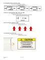
EXPLANATION OF THE TYPOGRAPHY USED:
DANGER
WARNING
TAKE CARE
BENETEAU 323
Apr. 01, 2004
rev 00
Page 1 of 85
RECEIPT
OWNER’S NAME
…………………………………………………………………………..
ADDRESS
…………………………………………………………………………..
…………………………………………………………………………..
………………………………………………………Zip:………………
Owner of the BENETEAU 323 number …………………………………………………………….
Does certify that I have accepted delivery and read the information in the owner’s manual delivered with the boat.
Signed on this____day of_______in the year________, _________________________________________________
Owners Signature
WARNING
The use of any boat or boat equipment and going to sea can be dangerous.
This manual is only a general maintenance guide, and it is not intended as an instructional manual on safety and
seamanship. The safety and security of your boat and its passengers are solely the responsibility of the owner
and/or the operator of the boat. Those not specifically and completely familiar with any particular aspect of the safe
and appropriate operation of a boat (or any piece of boat equipment) must obtain lessons, gain knowledge and seek
experienced advice, before proceeding to use a boat (or any piece of boat equipment). Your Beneteau dealer can
advise you on the availability of boating courses, sailing lessons and professional instruction in your area.
Please keep this portion for your records
>>>>>>>>>>>>>>>>>>>>>>>>>>>>>>>>>> cut here to separate>>>>>>>>>>>>>>>>>>>>>>>>>>>>>>>>>>>
RECEIPT
OWNER’S NAME
:
…………………………………………………………………………..
ADDRESS
:
…………………………………………………………………………..
…………………………………………………………………………..
………………………………………………………Zip:………………
Owner of the BENETEAU 323 number ……………………………………………………………….
Does certify that I have taken delivery and read the information in the owner’s manual delivered with the boat.
Signed on this____day of________in the year________, ________________________________________________
Owners Signature
Please return this portion to BENETEAU USA, Customer Service Dept, 1313 Hwy 76 West, Marion, SC 29571
WARNING
The use of any boat or boat equipment and going to sea can be dangerous.
This manual is only a general maintenance guide, and it is not intended as an instructional manual on safety and
seamanship. The safety and security of your boat and its passengers are solely the responsibility of the owner
and/or the operator of the boat. Those not specifically and completely familiar with any particular aspect of the safe
and appropriate operation of a boat (or any piece of boat equipment) must obtain lessons, gain knowledge and seek
experienced advice, before proceeding to use a boat (or any piece of boat equipment). Your Beneteau dealer can
advise you on the availability of boating courses, sailing lessons and professional instruction in your area.
BENETEAU 323
Apr. 01, 2004
rev 00
Page 2 of 85
I)
INTRODUCTION
Many parts and systems installed on your boat are supplied by other
manufacturers and each carries a specific warranty and may require specific care.
This manual supplements the literature supplied with the various equipment and we will
refer to manufacture’s literature throughout this booklet. We recommend referring to
original manufacturer's literature whenever possible.
This manual is broken down into several sections that attempt to help explain your
boat, your warranty, responsibilities as an owner, and maintenance of your new Beneteau.
Some of the equipment described in this manual are offered as options. The systems and
procedures described in this manual were correct to the best of our knowledge at the time
of printing and may be changed at any time or may have been changed on your boat.
While we have tried to describe the major points of your boat within this book, we cannot
cover every detail. Owning a boat and the operation of it are complex issues that can only
be mastered by vast experience and professional assistance. Please call your dealer or feel
free to call us if any question should arise.
If you are a seasoned sailor much of the manual may be old news, and if this is
your first boat, we hope this will prove useful, but we advise you to seek out professional
instruction through your dealer, sailing schools, the US Coast Guard auxiliary, US Power
Squadron, etc.
Should you need to contact Beneteau please use the following addresses and
numbers, be sure to include your model and hull identification number with any
correspondence.
Beneteau Customer Service
(Customer Service Dept.)
1313 Highway 76 West
Marion, SC 29571
Tel (843)-629-5300
Fax (843)-629-5329
We would like to sincerely thank you for choosing a Beneteau and we wish you good
sailing.
NOTE: Specifications, dimensions, capacities and descriptions are estimations given for general
information purposes, and they are not contractual in nature.
BENETEAU 323
Apr. 01, 2004
rev 00
Page 3 of 85
II)
ANTI-FOULING
The primary function of your Beneteau is to maximize your boating pleasure.
Your new Beneteau was made to last for many years. From the very beginning, care has
been taken in building your boat. Your years of pleasurable ownership are dependent
upon proper care and preparation.
Between the gel coat and the fiberglass laminate, Beneteau applied a Vinylester
resin that greatly reduces the phenomenon of osmosis and osmotic blistering. All
materials used in the construction of your Beneteau are of high production quality.
Sampling of materials and operational standards are monitored so that the structural
design matches the engineered standard. This, coupled with the mastery of building
techniques, allows Beneteau USA to offer you one of the most favorable structural
warranties in the marine industry.
Methodology for anti-fouling application when new:
1.
2.
3.
Clean and degrease hull thoroughly using a denatured ethyl alcohol
Sand hull using sandpaper with a minimum grit of #220. (i.e., 220, 300, or 400)
Rinse with fresh water.
DO NOT USE DETERGENTS. DO NOT PRESSURE WASH.
4.
APPLY ANTI-FOULING TO MANUFACTURER'S DIRECTIONS.
NOTE: It cannot be emphasized enough that thorough de-waxing must
occur. Furthermore, if the gel coat is abraded with coarse sandpaper,
the water imperviousness will be destroyed, and the warranty might be
voided.
BENETEAU 323
Apr. 01, 2004
rev 00
Page 4 of 85
III)
LIMITED WARRANTY
Beneteau USA Inc. ("Beneteau USA") warrants to the original purchaser or any subsequent buyer during the time of this Limited Warranty (the
"Owner"), that the boat, excluding parts or accessories not manufactured by Beneteau USA or Chantiers Beneteau, S.A., will be free from defects in
material and workmanship for a period of ONE year from the date of the delivery to the original purchaser.
In addition, Beneteau USA warrants to the Owner, except for the prototypes and boats from the California series, that the hull and deck structure of
the boat will be free from defects in material and workmanship for a period of FIVE years from the earliest of the following events: delivery of the
boat to the original purchaser, first date of utilization, last day of the boat model year.
Beneteau USA's obligation under this warranty shall be limited to the repairing or replacing (or causing to be repaired or replaced), at Beneteau
USA's option, the part or parts which are recognized defective by it in material or workmanship within the applicable warranty period to the
exclusion of all other remedies. This Warranty shall apply only provided that the Owner presents the boat's Certificate of Origin and gives the
selling dealer written notice of any claimed defect within 15 days after such defect is first discovered and satisfactory proof thereof. Warranty
repairs do not result in a renewal or extension of the original Warranty for the boat or a part thereof. Transportation charges and duties shall be
borne by the Owner.
This Warranty does not extend to: (1) any losses due to misuse, accident, disaster, abuse, neglect, normal wear and tear or improper maintenance;
(2) boats or any part thereof which have been repaired or altered without Beneteau USA's prior written approval; (3) accessories or parts not
supplied by Beneteau USA or Chantiers Beneteau, S.A., or, parts or accessories installed during the process of manufacturing that were not
manufactured by Beneteau USA or Chantiers Beneteau, S.A., for which the Warranty will be the one provided by the supplier of the part or
accessory; (4) damages resulting from any modification made to the boat; (5) boats for rental, lease, or charter; (6) splits, discoloration, or cracks in
the gel-coat (hull, rudder, and deck); (7) disorders in the hull, or deck such as, without limitation, blisterings, which are caused by use of improper
maintenance products or by improper sanding of the gel-coat; (8) anti fouling, varnishes, paints, acrylon, naugahyde, fabrics, headliners, chrome,
anodized coatings, keel coatings, sails, cushions, or running rigging, as these items are subject to deterioration caused by climate, erosion, normal
use conditions, or wear and tear; (9) reasonable and necessary maintenance, including, but not limited to, periodic re-bedding of chain plates,
stanchion bases, windows and/or window frames, and winches; (10) damages or deterioration due to the non-observance of maintenance
recommendations as described in the owner's manual or non-compliance with the normal rules of boat maintenance; (11) failure to take reasonable
measures necessary to protect the boat; (12) any damage or deterioration to the boat resulting from participation in a competitive sporting event.
In addition, if (1) any structural damage to the boat is suffered as a result of any cause other than a defect in material or workmanship (whether or
not such damage requires or results in any repairs to the hull or deck), or (2) any repairs or alterations to the boat of any nature whatsoever are made
at a shipyard not approved in writing by Beneteau USA, then the five-year hull/deck Warranty set forth above will immediately thereupon terminate
and be of no further force or effect.
THIS WARRANTY IS EXPRESSLY IN LIEU OF ALL OTHER WARRANTIES EXPRESS OR IMPLIED INCLUDING WITHOUT
LIMITATION THE IMPLIED WARRANTIES OF MERCHANTABILITY OR FITNESS FOR A PARTICULAR PURPOSE AND ALL OTHER
LIABILITIES ON BENETEAU USA's PART, AND BENETEAU USA NEITHER ASSUMES, NOR AUTHORIZES ANY PERSON,
INCLUDING THE DEALER, TO ASSUME FOR IT, ANY OTHER LIABILITY IN CONNECTION WITH THE SALE OF BENETEAU USA's
BOATS.
Beneteau shall in no event be liable to the Owner or any other person or entity for damages of any kind, including but not limited to direct, indirect,
special or consequential damages, arising from the sale or in connection with the use or inability to use the boat for any purpose whatsoever,
irrespective of whether the claims or actions for such damages are based upon contract, tort, negligence, strict liability, warranty, or otherwise.
For the purpose of compliance with the Federal Boat Safety Act of 1971 and all notification procedures set forth therein, Beneteau USA requests
that you complete the information requested below concerning your current address, which shall be returned to Beneteau USA by your Dealer.
Beneteau USA reserves the right, at any time, to make changes in design or additions to or improvements in the boats without liability or obligation
to incorporate such change, addition, or improvement in any boat manufactured prior thereto.
This Warranty gives you specific legal rights. You may also have other rights which vary from state to state.
--------------------------------------------------------------------------------------------------------------------------------------------------------------------------------I hereby acknowledge that Beneteau USA Inc. Limited Warranty was attached to Dealer's purchase order in its entirety at the time that I purchased
my boat from said Dealer; that I have read such Limited Warranty in its entirety; and that I have a copy of such Limited Warranty, as attached to
Dealer's purchase order, for future reference.
__________________________________________________________________________
Signature
__________________________________________________________________________
Purchaser’s Name/Please Print Clearly
__________________________________________________________________________
Mailing Address of Purchaser
__________________________________________________________________________
City State Zip
__________________________________________________________________________
(Area Code)
BENETEAU 323
Apr. 01, 2004
rev 00
Telephone Number
Page 5 of 85
Boat Model _________________________________________________________________
Hull # _____________________________________________________________________
Dealer _____________________________________________________________________
___________________________________________________________________________
Date ______________________________________________________________________
WARRANTY/REGISTRATION PROCEDURES
Warranty Procedure
Beneteau boats, unless specifically excluded, carry a one year limited warranty, as well as
an extended hull and deck structural warranty (see official warranty form for details). As
the first owner of your new Beneteau, your warranty only becomes valid upon receipt, by
Beneteau, of the completed and signed warranty form. It is important that you were
presented with this document at the time of your contract with your dealer and that
both you and your dealer have signed this form. Your warranty will then take effect
upon delivery to you of your new Beneteau.
Registration Procedure
As a new Beneteau owner you will automatically become a member of Club Beneteau.
Club Beneteau will entitle you to many added benefits and advantages as well as providing
you with a valuable line of communication with Beneteau. We will forward a new owner’s
package directly to 30 day after receipt of the completed and signed warranty form from
your dealer.
Subsequent owners of Beneteaus are invited to become a member of Club Beneteau as
well. We will automatically enroll these boat owners upon receipt of their warranty
transfer cards.
In the event that you change your address, please fill out and mail in the change of address
card at the back of the manual (to the address below) so that you will not miss any of Club
Beneteau's opportunities. You can also find a change of address form on line under CLUB
BENETEAU at www.beneteauusa.com.
If you have any questions concerning this procedure please feel free to contact Beneteau
Customer Service at at the number below.
Warranty Transfer
For a period of five years from date of manufacture, your new Beneteau has a transferable,
limited hull and deck warranty. In the event of selling your Beneteau, the new owner must
be registered with Beneteau within 30 days of the date of sale for the warranty to be
transferred.
Please fill in the appropriate warranty registration card at the back of this owner’s manual
and mail it to:
Beneteau USA Inc.
(Customer Service Dept.)
1313 Highway 76 West
Marion, SC 29571
Tel (843)-629-5300
Fax (843)-629-5329
BENETEAU 323
Apr. 01, 2004
rev 00
Page 6 of 85
IV)
HULL IDENTIFICATION NUMBERS
The hull identification or "BEY" number is a unique number given to your Beneteau alone.
This number begins with "BEY" which has been assigned to Beneteau by the USCG
followed by an alpha-numeric code which details the model, serial no., month of
construction, year of construction and model year.
Please clearly identify your boat using your model and "BEY" number during any
correspondence with Beneteau.
Your boat identification number appears in two places:
The main hull identification number is located on the aft starboard side, near the transom,
stamped into the hull, approximately 3 inches below the toerail.
The second hull identification number is in a hidden area for anti-theft purposes.
V)
DEALER'S RESPONSIBILITIES
Your Beneteau Dealer is an independent sales agency and they are a part of a worldwide
distribution network, with dealers in 28 countries. A Beneteau Dealer, has certain
obligations to you as the customer and to Beneteau as an authorized sales agency. A
Dealer’s responsibility does not end with the sale of your boat. Your Dealer is responsible
for the following:
BENETEAU 323
Apr. 01, 2004
rev 00
•
Delivering your new Beneteau to you complete, as ordered in your purchase
agreement.
•
Preparation of your boat for commissioning by their personnel, or another boat yard
contracted by them to accomplish the correct commissioning procedures.
•
Checking of all systems on the boat for fit, proper function and to familiarize you with
the usage of each system.
•
Sea trial of your new Beneteau with you as a final verification that all systems are in
good order.
•
Providing customer support and spare parts after you take delivery and any warranty
service under the terms of the limited warranty. All warranty questions/claims or
processing should be directed through your dealer.
Page 7 of 85
VI)
OWNER'S/OPERATOR'S RESPONSIBILITIES
STATE REGISTRATION OR FEDERAL DOCUMENTATION
For State Registration please consult your Dealer or the State offices in charge of boating,
who can provide the correct governmental department handling registration in your state.
Your Dealer also should be able to advise you on the possibility of Federal Documentation
with the US Coast Guard.
SAFETY AND MAINTENANCE
For maximum enjoyment of your Beneteau, due respect should be given to proper safety
and maintenance procedures.
Be sure that your boat is operated according to the U.S. Coast Guard Regulations as
outlined in the "Federal Requirements for Recreational Boats". Please familiarize yourself
with all operating requirements.
Prepare yourself for any situation before going out on the water. Follow the instructions
provided in the sections of this owner's manual, the individual supplier instruction
manuals, and all applicable U.S. Coast Guard and other regulations. If you are not an
experienced sailor, you should complete an accredited sailing course.
Before leaving the dock, be sure that all your equipment is in working order, that you are
aware of the weather conditions, and someone ashore is familiar with your destination or
sailing activities.
MANDATORY COAST GUARD SAFETY EQUIPMENT
Many safety items are required for compliance with the U.S. Coast Guard regulations.
Note that these regulations are subject to change. It is the owner's responsibility to be
aware of current regulations as outlined in the "Federal Requirements for Recreational
Boats". For your convenience a copy is included with your yacht’s documentation, and
additional copies may be obtained by calling the U.S. Coast Guard Boating Info line at
(800) 368-5647.
Good safety equipment should be a priority of every sailor for the protection and comfort
of passengers. Passengers aboard should be made familiar with the safety equipment and
operation of the boat in the event of an emergency.
Depending on the length, passenger capacity, and operating conditions, your boat must be
equipped according to the current USCG requirements. Be sure that you operate your boat
with the necessary number of life preservers, fire extinguishers, signaling devices, distress
signals, navigation lights as referred to in the "Federal Requirements for Recreational
Boats."
BENETEAU 323
Apr. 01, 2004
rev 00
Page 8 of 85
RECOMMENDED SAFETY EQUIPMENT
Preparation is the key to safety on the water.
Your new Beneteau has been fitted with the following equipment:
•
Compass - be sure that it is properly calibrated to give the correct magnetic reading.
•
A large capacity bilge pump.
We recommend that you fully outfit your Beneteau with safety equipment that can be
obtained through your dealer or marine supply outlets. These items should
include but not be limited to:
•
Up to date nautical charts covering your intended cruising area.
•
Boat hook.
•
Large waterproof flashlight with spare batteries.
•
Fenders.
•
Docking lines - a good rule of thumb to follow dictates that your bow, stern, and spring
line be equal to the length of the boat.
•
Life jackets, anchor, anchor chain and line, throwing line, flares, soft wooden plugs for
thru-hulls, life ring, fire extinguisher, and foghorn.
•
Electronics - Depth Sounder, Log Speedometer, and VHF Radio.
SAFETY COURSES
It is recommended that owners and operators gain knowledge and experience in boat safety
skills such as:
(a) Navigation
(b) Seamanship and boat handling
(c) Rules of the road, international and inland waterway
(d) Weather prediction
(e) Safety at sea
(f) Survival in bad weather
(g) Respect for others on the water
(h) First aid
(i) Radio communication
(j) Distress signals
(k) Pollution controls
To find out where one can attend these courses in your area, please call your dealer or "The
Boaters Educational Course Line" at (800) 336-2628.
BENETEAU 323
Apr. 01, 2004
rev 00
Page 9 of 85
ANCHORING
Various sea and bottom conditions require different anchoring systems. Your dealer can
help in choosing rode size and length, anchor chains, and working and storm anchors most
appropriate for your boat and location.
In general, a minimum of two anchors should be carried at all times and enough anchor
rode and chain necessary for the depth of water to be navigated during storm conditions.
Certain anchors are useful for a variety of bottom conditions. Study the charts of the area
to be navigated for information concerning bottom conditions and water depth.
The greatest hazard with a sound permanent mooring is chafe, which can occur to the rode
at the bow chocks. This is the single most common site of failure. Care is advised in the
selection and protection of the rode pennant with appropriate chafing gear. Careful and
regular inspection of moored boats on a regular basis is necessary to ensure the boat's
safety.
ADDITIONAL SAFETY EQUIPMENT
A number of additional safety items are worthy of your consideration. These range from
safety harnesses to emergency beacons, life rafts, and survival suits. Their use depends
upon the intended use of the yacht. We suggest you investigate the necessity of these
items through discussion with your dealer or local chandler.
MEDICAL KIT
Every yacht should carry a first aid manual, and a medical kit tailored to the specific needs
of the owner. Any ship's store should carry a standard type medical kit. Items in the kit
should include but not be limited to the following:
•
•
•
•
•
•
•
BENETEAU 323
Apr. 01, 2004
rev 00
Aspirin
Adhesive strips and tape
Antiseptic wipes
Gauze bandages
Sunscreen first aid/burn cream
Sterile pads
Ace bandages & splints
•
•
•
•
•
•
•
Page 10 of 85
Motion sickness pills
Ammonia inhalants
Antiseptic germicide ointment
Zinc oxide ointment
Insect/bee sting relief ointment/spray
Cold packs for sprains
Scissors & tweezers
TOOL KIT
A basic kit should consist of:
•
Wrenches - adjustable, Metric and SAE open end, box, socket
•
Hammers - large and small
•
Knife - with marlinespike
•
Screwdrivers - large and small, standard and Phillips
•
Pliers - regular, cutting and needle nose, vise grips
•
Wire cutter - capable of cutting standing rigging
•
Hacksaw - with spare blades
SPARE PARTS
A basic kit should consist of the following:
•
•
•
•
•
•
•
BENETEAU 323
Apr. 01, 2004
rev 00
Standing and Running Rigging: Turnbuckles, monel seizing wire, clevis and cotter
pins, shackles, blocks, extra line, rigging tape, duct tape.
Fasteners: Assortment of stainless steel screws, nuts, bolts, and washers
Hose clamps.
Electrical: Electrical tape, wire, crimps on lugs, spare navigation light bulbs.
Lubricating supplies: WD-40 and silicone grease.
Engine: Check engine manual for spare parts, engine oil and transmission fluid
recommendations.
Sails: Sail repair kit and sail slides.
Page 11 of 85
VII)
SAFE OPERATION AND WARNING LABELS
Ensure that the boat operator is not under the influence of drugs and/or alcohol.
Do not venture out in weather or sea conditions beyond the skill or experience of the
operator.
There are "Warning" and "Caution" statements affixed to your Beneteau. These are
detailed below with location:
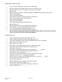
FUEL WARNING LABEL
•
Affixed to the fuel tank.
Beneteau Part #111358
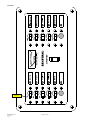
SHORE-POWER LABEL
•
At the 110V distribution panel.
Beneteau Part #111359
BENETEAU 323
Apr. 01, 2004
rev 00
Page 12 of 85
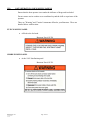
PROPANE LABELS
•
At the propane stove affixed to the bulkhead in the galley
Beneteau Part #111353
Beneteau Part #111357
BENETEAU 323
Apr. 01, 2004
rev 00
Page 13 of 85
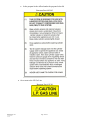
•
In the propane locker affixed under the propane locker lid
Beneteau Part #015903
•
On or next to the LP Gas Line
Beneteau Part #111361
BENETEAU 323
Apr. 01, 2004
rev 00
Page 14 of 85
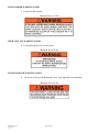
SWIM LADDER WARNING LABEL
•
Located on the transom
Beneteau Part # 111354
HIGH VOLTAGE WARNING LABEL
•
Located beside the 110v electric panel.
Beneteau Part #111365
TRANSOM DOOR WARNING LABEL
•
Located on or next to the helmsman’s seat. (Not applicable on all models)
Beneteau Part #111362
BENETEAU 323
Apr. 01, 2004
rev 00
Page 15 of 85
STANDARD BATTERY SWITCH LABEL
• Located at the standard battery switches.
Beneteau Part #111363
OPTIONAL INVERTER BATTERY SWITCH LABEL
• Located at the battery switches
Beneteau Part #112624 (Not applicable on all models)
SLING LOCATION ARROWS LABEL
• Located at or near the hull to deck joint
Beneteau Part #111364
ANTI FREEZE CAUTION TAG
• Tied to the breaker for the water
Beneteau Part #111046
BENETEAU 323
Apr. 01, 2004
rev 00
Page 16 of 85
VIII)
FEDERAL/STATE REGULATIONS
DISCHARGE OF OIL
•
Located: under the sail locker lid.
Beneteau Part #111352
BENETEAU 323
Apr. 01, 2004
rev 00
Page 17 of 85
SOLID WASTE DISPOSAL
•
Located under the sail locker lid.
Beneteau Part #111356
MARINE SANITATION
Your Beneteau is equipped with an USCG approved marine head and holding tank.
By law you must use a holding tank in all U.S. waters, Check with local
authorities for regional laws governing your area before selecting the
overboard discharge option.
BENETEAU 323
Apr. 01, 2004
rev 00
Page 18 of 85
ACCIDENT REPORTING
Knowledge of accident reporting requirements. Please refer to the following list for a
copy of the U.S. Coast Guard Boating Accident form. For further information on where
to obtain more forms, please call the U.S. Coast Guard Boating Safety Hotline at (800)
368-5647
NATIONAL VESSEL DOCUMENTATION CENTER
2039 STONEWALL JACKSON DR.
FALLING WATERS, WV 25419
TOLL FREE: 1-800-799-8362
PHONE:
(304) 271-2400
FAX:
(304) 271-2405
RENDERING ASSISTANCE
United States Code, Title 46:
"The owner or operator of a vessel is required by law to render assistance to any individual
or vessel in distress, so long as his vessel is not endangered in the process."
BENETEAU 323
Apr. 01, 2004
rev 00
Page 19 of 85
IX)
COMMISSIONING
COMMISSIONING PROCEDURES
The first commissioning of a yacht is essentially the start of its life, and the importance of
proper commissioning procedures at this time cannot be overstated. The first
commissioning procedure must be performed by an authorized Beneteau dealer or those
authorized by them. The dealer will also have a commissioning checklist to be signed by
the owner and a dealer representative at the time of the first commissioning. The owner
also needs to concern himself with items such as safety equipment, which is considered to
be his responsibility. See the Owner’s Operator’s Responsibilities section for details.
Lists of the pre-launch and post-launch checks employed during commissioning are
provided in this section for those owners interested in understanding the commissioning
procedure, as well as for future use in any recommissionings that may be required after
periods of wet or dry storage. The lists are of a general nature and do not attempt to
provide step-by-step instructions.
The following is a list of minimum commissioning duties. Additional
operations may be required dependent upon the model & equipment
PRIOR TO LAUNCH
_____
_____
_____
_____
_____
_____
_____
_____
_____
_____
_____
_____
_____
_____
All accessories & options supplied per shipping list and boat order
Check hull and repair any shipping damage - aft end of keel, rudder, etc.
Prep bottom and apply bottom paint if needed.
Thru hulls inspected and closed.
Clean hull thoroughly.
Check clamps on all thru hulls below waterline.
Wax hull topsides.
Dock lines and fenders aboard.
Check tightness of nuts on prop shaft and zinc. (Folding props require additional steps).
Check steering system (rudder moving freely stop to stop and does not touch hull?).
(Hydraulic steering requires all fittings be checked and the system is bled)
Zincs installed.
Thru hulls unobstructed and speed/log impeller in place (if applicable).
Fuel valve turned ON.
Check keel bolts for tightness.
BENETEAU 323
Apr. 01, 2004
rev 00
Page 20 of 85
OPERATIONS AFTER LAUNCH
_____
_____
_____
_____
_____
_____
_____
_____
_____
_____
_____
_____
_____
_____
_____
_____
_____
No water leaks, stuffing box, shaft log, strut, rudder post.
No leaks at thru hulls; all hose clamps secure with seacocks open.
Fill water tanks, no leaks at fill pipes, overflows or connections.
Fill fuel tank.
Batteries secured, connected, filled and charged. (NOTE: Beneteau ships batteries dry)
Check all cabin lights.
Check all navigation lights.
Water pressure system - air bled, no leaks at connections.
Check electric sump pumps and bilge pump.
Check manual bilge pump
Check emergency tiller fit.
110V shore power polarity ok and breakers on
Battery charger ok.
Hot water heater works-must be filled before turning on.
Check head(s) operation and holding tank(s) for leaks.
Test wash down pumps, refrigeration, heaters, etc.
Test stove and LPG tank for leaks and proper operation
DO NOT TEST FOR LEAKS WITH AN OPEN FLAME, WIPE EACH JOINT WITH A
SOAPY SOLUTION AND LOOK FOR BUBBLES
ENGINE START-UP
_____
_____
_____
_____
_____
_____
_____
_____
_____
_____
_____
_____
_____
_____
_____
_____
_____
_____
_____
_____
Check transmission for proper fluid and proper level.
Check crankcase dipstick for proper fluid and proper level.
Check shift and throttle cables for proper adjustment and secure end fittings.
Engine alarms work when key is on.
Open engine water intake.
Start engine, check gauges and water flow at exhaust is normal.
Check water level in heat exchanger and expansion tank.
Check belts and mounts.
Run engine at operating temperature. Note temperature _______degrees.
No engine or fuel line leaks-no chafe problems with wires.
Forward and reverse gears operate.
After warm-up, shut engine down, check oil, and fluid levels again.
Alignment to under .003 - coupling bolts tightened.
Idle set correctly , engine won't stall when put in gear. Idle set at _____ RPM.
Allow engine to run for at least (1) hour.
No leaks at the shaft seal.
Shift and throttle operate smoothly with engine running.
No leaks at keel bolts after engine run.
Test run boat, check all operations of shifting, controls etc.
Maximum RPM in gear ___________.
BENETEAU 323
Apr. 01, 2004
rev 00
Page 21 of 85
PRIOR TO STEPPING MAST
_____
_____
_____
_____
_____
_____
_____
_____
_____
_____
_____
_____
_____
_____
_____
_____
Clean or wax spar.
Mast sheaves free running.
Run halyards if necessary– Make sure you have clean hands on clean ground.
Attach and secure all stays and shrouds.
Attach and secure spreaders to mast and upper shrouds.
Check boom gooseneck fitting.
Install mast boot on spar if applicable.
Check all mast lights.
Attach and secure boom topping lift.
Check running lights and electrical connections.
Protect against chafe on spreader ends and any fitting.
Check sail track for burrs.
Turnbuckles attached.
Re-check all pins, cotters, and Locktite any shackles.
Check with salesman and work order for additional mast gear.
Furling system built and connected to mast
AFTER STEPPING MAST
_____
_____
_____
_____
_____
_____
_____
_____
_____
_____
_____
Protect spar from scratching on mast collar on keel stepped masts.
Turnbuckles lubricated.
Attach standing rigging to chain plates.
Chock mast partner and seal mast boot on keel stepped masts.
All mast wiring connected.
Preliminary tune - spar straight - shrouds proper tension.
Run reefing lines and halyards.
All cotter pins in place on turnbuckles and opened.
Run main sheets and attach topping lift.
Tape chain plates and cotter pins to prevent chafe.
Check and double-check all turnbuckles, cotter and clevis pins.
BENETEAU 323
Apr. 01, 2004
rev 00
Page 22 of 85
PRIOR TO DELIVERY
_____
_____
_____
_____
_____
_____
_____
_____
_____
_____
Hose test all ports, deck hardware, chain plates, and stanchion posts for leaks.
Tighten lifelines and tape split rings.
All doors, drawers, floorboards, hatches, and cabinets operate freely - fit if necessary.
Clean thoroughly: sinks, bulkheads and counter tops, all lockers and drawers, bilge, cushions,
deck and cockpit lockers.
Dry the bilge completely.
Clean and oil exterior teak if needed.
Clean cabin sole, deck area and ports.
All Coast Guard and safety gear aboard.
Sails bent on, ALL HEADSAILS (AND MAINSAIL) FIT FURLING. Operate freely.
All electronics and optional gear tested and working.
DELIVERY TO OWNER
_____ Walk through the boat with manuals and owner, showing operation of all components.
_____ Test sail boat with owner showing all operations.
_____ Fill out warranty certificates.
BENETEAU 323
Apr. 01, 2004
rev 00
Page 23 of 85
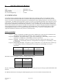
X)
SPECIFICATIONS OF THE BOAT
Type .......................................................
Name of Builder ....................................
Design Category.....................................
No. of acknowledged body.....................
BENETEAU 323
BENETEAU USA INC.
B
CE 0607
CE CERTIFICATION
Your Beneteau has been manufactured in the United States and has been certified by ICNN to be in compliance with the
relevant parts of the Recreational Craft Directive 94/25/EC from the European Parliament. The CE mark means your boat
meets or exceeds all current International Organization for Standardization (ISO) standards and directives in effect at the time
of manufacture. The builders plate located in the cockpit of your boat, gives information pertinent to this certification, such as;
model, design category with corresponding max. number of persons recommended, and max. load weight. Following are the
design categories established by the Recreational Craft Directive. This is a guideline only, the safety of those on board your
boat are only measurable by the experience and skill of the captain and crew, together with proper preparation and appropriate
safety equipment for the given conditions, in addition to a well maintained boat. This certification only applies to factory
installed equipment and does not cover equipment installed by the dealer or owner. In the case of European travel such
equipment installed after manufacture may need to be certified separately.
DESIGN CATEGORIES
Category A: OCEAN – Designed for extended voyages where conditions may exceed wind force 8 (Beaufort scale)
and significant wave heights of 4 m and above, and vessels largely self sufficient
Category B: OFFSHORE – Designed for offshore voyages where conditions up to, and including, wind force 8 and
significant wave heights up to, and including, 4 m may be experienced.
Category C: INSHORE – Designed for voyages in coastal waters, large bays, estuaries, lakes and rivers where
conditions up to, and including, wind force 6 and significant wave heights up to, and including, 2 m may
be experienced.
Category D: SHELTERED WATERS – Designed for voyages on small lakes, rivers, and canals where conditions up
to, and including, wind force 4 and significant wave heights up to, and including, 0.5 m may be
experienced.
Category
A
B
C
D
Height of the Waves
(ft)
> 4 m (13.0 ft)
< 4 m (13.0 ft)
< 2 m (6.5 ft)
< .5 m (1.6 ft)
Wind Force
(Beaufort)
>8
<8
<6
<4
Maximum recommended number of persons on board by design category:
Category
Maximum Number
of Persons
A
B
C
D
6
8
10
The C.E. Certified equipment includes: The fuel tanks, parts of the steering system, parts of the gas system and the hatches and
portholes.
For additional information concerning the standard equipment, please refer to the manuals enclosed with the boat.
BENETEAU 323
Apr. 01, 2004
rev 00
Page 24 of 85
Length Over All
10.00 m
32.81 ft
Hull Length
Length Waterline
Hull Beam
Draft:
(from waterline)
9.72 m
8.89 m
3.27 m
31.89 ft
29.17 ft
10.73 ft
1.45 m
1.80m
14.85 m
4.76 ft
5.91 ft
48.72 ft
Centerboard
Shoal
Deep
Clearance Height (from waterline)
Maximum Authorized Engine Power :
25 kW
Fuel Capacity
Fresh Water Capacity
Waste Tank Capacity
Battery Capacity
33 hp
65 L (17.2 US gal)
182 L (48.1 US gal)
50 L (13.2 US gal)
75A engine
75A house
WEIGHT ESTIMATION
SAILING CATEGORIES
A
B
C
D
Kg (lbs)
Kg (lbs)
Kg (lbs)
Kg (lbs)
4230 (9326)
4230 (9326)
4230 (9326)
Life Raft :
Crew :
Water :
Fuel :
Personal Equipment :
55 (121)
450 (992)
160 (353)
60 (132)
270 (595)
55 (121)
600 (1323)
160 (353)
60 (132)
160 (353)
55 (121)
750 (1654)
160 (353)
60 (132)
50 (110)
Optional Equipment
Air Conditioning
Holding Tank :
Auto Pilot Gear :
Mech. Refrigeration
Furling Mast
Spinnaker Gear :
Microwave Oven :
Roof Sprayhood :
Bimini :
SUB TOTAL
(Optional Equipment)
80 (176)
60 (132)
10 (22)
20 (44)
20 (44)
10 (22)
5 (11)
10 (22)
10 (22)
225 (496)
80 (176)
60 (132)
10 (22)
20 (44)
20 (44)
10 (22)
5 (11)
10 (22)
10 (22)
225 (496))
80 (176)
60 (132)
10 (22)
20 (44)
20 (44)
10 (22)
5 (11)
10 (22)
10 (22)
225 (496))
Margin for Other Equipment
80 (176)
40 (88)
0 (0)
5530 (12,192)
5530 (12,192)
5530 (12,192)
1300 (2866)
1300 (2866)
1300 (2866)
Light Displacement :
Includes:
Light Boat + Safety Equipment + Sails
MAXIMUM LOAD DISPLACEMENT
Kg (Lbs.)
MAXIMUM LOAD
Kg (Lbs.)
MAXIMUM LOAD = MAXIMUM LOAD DISPLACEMENT – LIGHT DISPLACEMENT
ANY OVERLOADING CARRIES A RISK OF FLOODING OR LOSS OF STABILITY
BENETEAU 323
Apr. 01, 2004
rev 00
Page 25 of 85
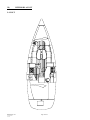
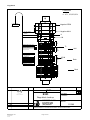
XI)
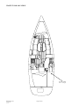
INTERIOR LAYOUT
LAYOUT
BENETEAU 323
Apr. 01, 2004
rev 00
Page 26 of 85
EXIT IN CASE OF FIRE
=
Emergency Exit
=
Recommended Fire Extinguisher Location
= Engine Compartment Fire Extinguisher Port
BENETEAU 323
Apr. 01, 2004
rev 00
Page 27 of 85
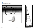
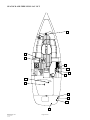
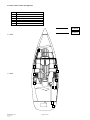
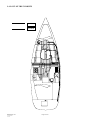
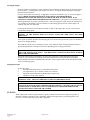
XII)
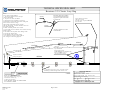
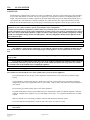
DECK
- Jack lines can be fastened either to the mooring cleats, or to pad eyes on deck.
The Beneteau 323 is fitted with a foldaway swimming ladder. The swimming ladder
should be in its folded/upright position as soon as you are on board.
The transom area is not considered part of the working deck and should not be used while underway
See diagram below
Make sure that the hatches and portholes are closed before you put out to sea.
In case of rough sea, close the boat with the sliding hatch and weatherboards so that no water may come into
the boat.
Check that nothing blocks the cockpit drain holes; these holes should never be sealed.
1
2
3
4
5
Recommended location of the life-raft
Fwd water tank deck fill
Waste tank pump out deck plate
Fuel deck fill
Swim ladder
Recommended Fire Extinguisher Location
Zones excluded from working deck
2
6
1
5
BENETEAU 323
Apr. 01, 2004
rev 00
4
Page 28 of 85
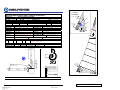
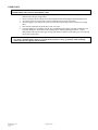
XIII)
SAILS AND RIGGING
SPECIFICATIONS OF THE SAILS:
SAIL
AREA
Roller furling main Classic main
Total
Mainsail
Genoa (116%)
48.1 m2
23.5 m2
24.6 m2
Specifications of the Standing Rigging:
V: VERTICAL - D: DIAGONAL
REF CABLE
1
V1D2
2
D1 AFT (Aft Lower Shroud )
3
Forestay
4
Double Backstay
51.7 m2
27.1 m2
24.6 m2
Roller furling mast
I
13.006 m
Classic mast
I
13.006 m
J
P
E
J
P
E
3.372 m
11.71 m
4.015 m
3.372 m
11.86 m
4.015 m
Dia. In.
1/4
1/4
1/4
3/16
P
E
J
4
3
2
1
Q
BENETEAU 323
Apr. 01, 2004
rev 00
Page 29 of 85
Apr. 01, 2004
rev 00
Page 30 of 85
13158
13263
CONTROL LENGTH
12849mm
42ft 1-7/8in
NOTE:
ALL MEASUREMENTS TAKEN WITH
TURNBUCKLES 2/3 OPEN
00000
52
Do not supply top pin on toggle.
Tie-wrap toggle to removable eye.
NOTE:
Fasten removable eye
to double jaw toggle
and roller furling unit
link plates using Profurl
threaded stepped pin
supplied with roller
furling unit.
REMOVABLE
EYE SWAGE
WITH
1/2" HOLE
RME0816
1/4"
1X19
W IRE
N546-0816
MARINE
EYE SWAGE
WITH HOLE FOR
1/2" PIN
ME08
JAW AND JAW
TOGGLE
J200-1616
CONTROL LENGTH
13211mm
43ft 4-1/8in
BENETEAU 323
00000
3/8"
BLANK + TOGGLE
TURNBUCKLE
N674-001212
3/8"
STUD SWAGE
SWS0812
1/4"
1X19
WIRE
13030
STEMBALL SWAGE
SB08 +
BACKING SHELL
Z428
V1D2
CONTROL LENGTH
14073mm
46ft 2-1/16in
Add double turnbuckle
+ masthead toggles to
backstay
BDB 12/03/03
BENETEAU USA INC.
N°:112727
01
THIS DOCUMENT IS - PROPRIETARY AND REPRODUCTIONS MUST BE AUTHORIZED BY BENETEAU - DRAWN BY BENETEAU - SPECIFIED AND
DESIGNED BY PRODUCT MANUFACTURER.
Tel. (843) 423-4201 - Fax. (843) 423-4912
1313 HIGHWAY 76 WEST
PO DRAWER 1218 , MARION,SC 29571
Design Date : 09/01/03
By : BDB
Approved Date :
By :
Weight :
Visa :
00000
5/16"
BLANK + TOGGLE
TURNBUCKLE
N674-001010
5/16"
NAVTEC SCREW
D320S10
5/16"
TURNBUCKLE BODY
TBBO10
5/16"
STUD SWAGE
SW S0610
N555-0610
3/16"
1X19
W IRE
MARINE EYE SWAGE
WITH 3/8" HOLE
ME06
N546-0612
STANDING RIGGING KIT O323
BOX 1/1
Gen.Tol.:
14430
14470
3/8" EYE & JAW TOGGLE
EJT12 (CSJ 12-122)
TWIN BACKSTAYS
Dimension in mm :
Scale:
00000
3/8"
BLANK + TOGGLE
TURNBUCKLE
N674-001212
3/8"
STUD SWAGE
SWS0812
1/4"
1X19
WIRE
STEMBALL SWAGE
SB08 +
BACKING SHELL
Z428
6721
R DESCRIPTION By DATE
01
CAUTION
CAO
DRAWING
Material :
D1 AFT
CONTROL LENGTH
6541mm
21ft 5-1/2in
FORESTAY
STANDING RIGGING
BENETEAU 323
Apr. 01, 2004
rev 00
Page 31 of 85
SAILS
Headsail Specification and Technical Worksheet
12620
Max Hoist:
4075
Foot:
Tack Detail:
Clew Detail:
Foot Cleat:
U.V. Cover:
Leech/Foot Line:
Trim stripe:
Seam:
Furling System:
Date:
11-02
Area:
23.75m2
L.P.:
116% /3911
Double webbing Loop
40mm external ring with leather
2 #1 eyelets at tack
U.V. Dacron w/top backside cover
3mm Polyester
2 x 3/8" in black
V-92 Blue / 2 rows 3-step
Ref: Beneteau # 112729
Rev. #
112736 rev0 - 0323 rf genoa.doc
UV cover / starboard
Model Type:
Beneteau 323
Roller Furling Genoa
Sail Type:
13006
3372
“I” Dim:
“J” Dim:
Finished Dimensions
12450
11780
Luff:
Leech:
Finish Details
5.9 Contender
Material Type:
Double Webbing Loop
Head Detail:
241 aluminum cleat w/snubbing eyes
Leech Cleat:
Single fold, hot-knifed 25mm tabling
Foot/Leech:
9inch vinyl
T.T. Window:
NP #5
Foil Tape:
Drawstring type "a'
Bag Type:
Std. NP Ditty Bag Kit
Ditty Bag:
Drawing Information
Drawing Name:
B323 RFG
Drawn By:
BP
Additional Notes:
Prototype Genoa.
Tack Detail with reefing tabs
BENETEAU 323
Apr. 01, 2004
rev 00
Page 32 of 85
Beneteau Part #:
112736
u.v.cover
both sides
Mainsail Specification and Technical Worksheet
Model Type:
Sail Type:
“P” Dim: 11710
Beneteau Oceanis 323 USA
Roller Furling Mainsail
4015
“E” Dim:
Sailmaker “E”
Area:
22.00sqmt
Finished Dimensions
Luff:
Leech:
11582
Foot:
11814
3977
Z-Spar 3259
Finish Details
Material Type:
Head Detail:
Clew Detail:
Furling Label
Draft Stripe:
Leech Cleat:
Luff Rope
7.4 Contender
Tack Detail:
Single ply 25mm webbing loop
Single ply 25mm webbing loop
Clew Slug/Car: Z-spar 3259 Clew block
Pg 38 safety clew ring with webbing
Insignia:
Yes, black
120mm behind UV Cover
Seams:
2 rows of 3-step, Blue V-92
2x3/8" black
Tell Tale:
Yes, 2 at leech
241 Alum cleat with snubbing eyes
Bag Type:
Drawstring type “B”
NPS#6 Foil Tape Luff tape ends at the
Cover Material/Colour:
Clew only, both sides: UV
foot/luff intersection.
Dacron cloth / white
Zspar-400E
Boom Section
Zspar – z360
Mast Section:
C A U TIO N !
M
a
ins
ail m
us
t b
e fu
rle
d s
o tha
t
this lin
e is in
sid
e the m
as
t
F
a
ilu
retod
os
ow
ill c
a
u
s
ep
re
m
a
tu
r
eb
re
a
k
w
h
en the m
a
ins
ail is n
ot in u
se
.
d
o
w
no
fth
es
a
ilc
lo
thd
u
etos
u
n
lig
h
td
a
m
a
g
e
,
w
h
ic
hisn
o
tc
o
v
e
re
db
yw
a
rra
n
ty
.
120 mm
Tack and Clew Cutback Details:
A:
50
B:
100
Drawing Information
Bob
Drawn By:
Additional Notes:
C:
100
Note: These are for design reference only; sail does not have cut
back or cut out at foil tape.
Nov-03
Date:
Revision #
Finished Dimensions include head and tack webs.
112735 - R000 - RF Mainsail.doc
"B"
u.v.cover
both sides
"C"
Rise:
8 5mm per 10 0 0 mm of E
"A "
Boom
CAUTION!
Ma insa il must be furled so th at
this line is inside the mast
when t he ma insa il is n ot in u se .
C
A
U
T
IO
N
!
F a i lu r e t o d o s o w i l l c a u s e p r e m a tu r e b r e a k d o wn o f th e s ai lc l ot h d u e to s un l ig h t d am ag e ,
w h i c h i s n o t c o v e r e d b y w a r r a n t y.
Tack/Clew Detail
Apr. 01, 2004
rev 00
F
a
u
l
i
r
e
o
t
d
o
s
o
w
i
l
c
a
u
s
e
p
r
e
m
a
t
u
r
e
b
r
e
a
k
t
h
i
s
l
i
n
e
i
s
n
is
i
d
e
t
h
e
m
a
s
t
w
h
c
i
h
i
s
n
o
t
c
o
v
e
r
d
e
b
y
w
a
r
r
a
n
t
.
y
Black Insignia & Furling Label
Please refer to most recent drawings Specifications subject to change with prior consent from Beneteau Copyright Neil Pryde
BENETEAU 323
M
a
i
n
s
a
i
l
m
u
s
t
b
e
f
u
r
l
e
d
s
o
t
h
a
t
d
o
n
w
o
f
t
h
e
s
a
l
i
c
o
l
t
h
d
e
u
t
o
s
u
n
g
i
l
h
t
a
d
m
a
e
g
,
w
h
e
n
t
h
e
m
a
i
n
s
a
il
i
s
n
o
ti
n
u
s
e
.
Page 33 of 85
Beneteau Part #:
112735
Mainsail Specification and Technical Worksheet
Model Type:
Sail Type:
“P” Dim:
Beneteau 323
Classic Mainsail
“E” Dim:
11860
4015
Area:
26.61sqmt
Finished Dimensions
Luff:
Material Type:
Head Detail:
Head Slide:
Clew Reef 1:
Clew Reef 2:
Ditty Bag:
Battens:
Bat. Lengths:
Luff Slides:
Leech Cleat:
Luff Tape:
Leech Line:
Reef Cleat:
Reef Hts. %
Reefing slots:
Reef eyes:
Mast Section:
A:
Leech:
11733
40
Drawing Name:
Foot:
12242
Finish Details
6.9 Contender Dacron
Tack Detail:
40mm S.S. ring with leather
Clew Slug/Car:
Metal Seldon 661B set just below head
Clew Detail:
ring.
34118 Wichard block on Port Side led
Tack Reef 1:
through PG 23 ring
34118 Wichard block on Port Side led
Tack Reef 2:
through PG 23 ring
Packaged with headsail
Logos
Ben. Part#:
4 x 25mm flat
#1
#2 1500
#3
750
2000
Tell Tale:
16-661A seldon slides
DraftStripe:
241 Alum. With snubbing eyes
Luff eyes:
4" with 6mm rope
Insignia:
3mm Dacron line
Bag Type:
2 x 241 Alum.
Reef 1
Reef 2
13.8%
30%
Foot /Leech Tape:
None
Sail Ties:
6- # 2 eyelets
Boom Section:
Z-Spar 401
Tack and Clew Cutback Details:
B:
000
C:
200
D:
000
E:
25
Drawing Information
323 classic
Bob
Sept-03
Drawn By:
Date:
Additional Notes:
3967
40mm SS Ring with leather
SLD 151
40mm SS ring with leather
120mm
PG 23 @ leech
PG 20 @ luff
33118 @ luff
34118 @ leech
33118 Wichard block on Port Side
led through PG 20 ring
33118 Wichard block on Port Side
led through PG 20 ring
2 bullseyes
112734
#4
#5
2500
n.a.
4x 1 at each batten
1 in black
16-#3 eyelets
Black ‘Beneteau 323”
Drawstring type “a”
Reef 3
na
Double tabling
Yes, 2 x 2.4 mt ties
Z-Spar 360
F:
Rev:
200
G:
120
Reef
112732-rev0-cl
mainsail.doc
Production Model Classic Main
Re e f e y e
Reef
"G "
Tack Gat e
"C"
"E"
"B"
"D"
Boom
"A"
"F"
Tack/Clew Detail
Insignia Detail in Black
Beneteau Part #:
BENETEAU 323
Apr. 01, 2004
rev 00
Page 34 of 85
112732
TECHNICAL SPECIFICATION SHEET
Beneteau 323 Classic Lazy Bag
Notes:
Cover: Forest Green Odysey
1. Top section folded over to accept a
11mm round batten
2. Top sewn to seam. See detail
3. Openings for line notched in as shown.
4.Front flap to fold inside bag while sailing and
Velcro to the interior of bag.
5.Web loops and buckle at fore and aft
ends for tensioning. ***these should be sewn on
the inside of the bag
6. Back of batten 'pocket' sewn closed.
7. Front needs to have internal velcro closure to keep
batten in place.
8. One half of the top with extra tabling width
to provide for zipper 'flap'.
9. One Bullseye on each side of bag
10. 2 number 2 eyelets on both sides of
rear of bag for tensioning purposes
Side panels form loop by folding
over onto themselves and sewing.
Top panel is in place and is sewn
in at same time
Zip-Flap
zip
Zipper half to both sides
and sewn to front
Fore/aft zipper to pull FORWARD
from aft end.
Stitching
Notches in pockets are cut and
hot knifed later
1282mm
495mm
1447mm
165mm
#2 Eyelet in each half
of bag for tie purposes
774mm
Top and Bottom
Front support straps:
25MM Webbing loop 1000mm long
Sewn to INSIDE of cover
(not externall as shown)
4058mm
200MM
7- Grommets each side of cover at 623mm centers.
604B Slugs webbed through both sides of cover.
Buckle and loop 25mm x 500mm
Loop goes through corner rings and
back to other side of bag
to allow for tensioning.
NOTE: BUCKLE TO BE SET INSIDE REAR
OF COVER BY 200MM
BENETEAU 323
Apr. 01, 2004
rev 00
Neil Pryde Sails Int .
354 Woodmont Rd #18
Milford Conn. 06460 U.S.A.
Phone: 203-874-6984 Fax: 203-877-7014
Drawing Name: 323 Lazy Bag
Date:
Sept -03
Scale: Not to Scale
Drawn by: Bob Pattison Rev: 000
Copyright 20 0 3 Neil Pryde Sails
Page 35 of 85
TECHNICAL SPECIFICATION SHEET
Beneteau 323 lazy jack lines
Material List for BOTH SIDES
4- 30mm rings
30mts of 5mm line
Lines will be tied around round batten
stock that is exposed in cutouts
6000mm
Note: lengths approximate until fitted.
Final Cuts after Annapolis boat show
5000mm
4000mm
Neil Pryde Sales & Design Office
50 Broad Street, Milford Conn. 06460 U.S.A.
Phone: 203-874-6984 Fax: 203-877-7014
Drawing Name: 323 Lazy Jack lines
Date:
Sept 03
Scale:
Not to Scale
Drawn by: Bob Pattison
Revision #: 000
File Name:
BENETEAU 323
Apr. 01, 2004
rev 00
Page 36 of 85
393 Line
DECK LAYOUTS
DECK LAYOUT FOR ROLLER FURLING MAST + OPTIONAL GENNEKER
The optional foreguy attaches to port Wichard pad eye on forward part of coachroof,
then led thru single block + snapshackle on spi pole,
then led thru single block attached to starboard Wichard pad eye on forward part of coachroof,
then led aft as shown.
- Main boom topping lift cleated on general purpose
cleat on port side of mast.
- Jib halyard n°1 made off on clamcleat on port side
of mast, led thru a mast step block and stowed on a
general purpose cleat on the mast.
1110
Jib halyard n°1
- The vang line is led thru a single swivel block
shackled to the lower hole of the toggle on the vang
bracket on the mast, then led aft as shown.
- The genoa roller furling line runs along the port
toerail thru lead blocks, then led thru a Harken pivot
block and cam cleat, then to the primary winch.
6-way deck
organizer
Traveller
Main halyard
Outhaul
Inhaul
Vang
Mainsheet
Traveller
Mainsheet
track &
traveller
system
opt
Genneker halyard
Spi pole topping lift
Foreguy
std
- Install optional Spinlock XAS1 and XAS2 in
position shown.
- Optional XAS1 is supplied for genneker halyard
and must be installed where XAS1 opt is shown.
XAS2 opt
XAS1 opt
XAS2 std
XAS2 std
XAS1 std
Spinlock
stoppers
Manoeuvering
winch 30cst
std
opt
opt
opt
opt
std
std
std
Line hanger
Genoa roller
furling line
Primary winch 30cst
Material :
DESCRIPTION
Gen.Tol.:
MAST STEP, STOPPER & WINCH LAYOUT Design Date : 01/20/04
By : BDB
O323 RF
Approved Date :
By :
BENETEAU USA INC.
Weight
:
1313 HIGHWAY 76 WEST
CAUTION
CAO
DRAWING
R
Visa :
Dimension in mm :
Scale:
By
DATE
PO DRAWER 1218 , MARION,SC 29571
Tel. (843) 423-4201 - Fax. (843) 423-4912
14323AU20
N°:
THIS DOCUMENT IS - PROPRIETARY AND REPRODUCTIONS MUST BE AUTHORIZED BY BENETEAU - DRAWN BY BENETEAU - SPECIFIED AND DESIGNED BY PRODUCT MANUFACTURER.
BENETEAU 323
Apr. 01, 2004
rev 00
Page 37 of 85
DECK LAYOUT FOR CLASSIC MAST + OPTIONAL GENNEKER
The optional foreguy attaches to port Wichard pad eye on forward part of coachroof,
then led thru single block + snapshackle on spi pole,
then led thru single block attached to starboard Wichard pad eye on forward part of coachroof,
then led aft as shown.
- Main boom topping lift cleated on general purpose
cleat on port side of mast.
- Jib halyard n°1 made off on clamcleat on port side
of mast, led thru a mast step block and stowed on a
general purpose cleat on the mast.
1110
Jib halyard n°1
- The vang line is led thru a single swivel block
shackled to the lower hole of the toggle on the vang
bracket on the mast, then led aft as shown.
- The genoa roller furling line runs along the port
toerail thru lead blocks, then led thru a Harken pivot
block and cam cleat, then to the primary winch.
6-way deck
organizer
Traveller
Main halyard
Reef 2
Reef 1
Vang
Mainsheet
Traveller
Mainsheet
track &
traveller
system
- The mainsail outhaul is cleated on the boom.
opt
Genneker halyard
Spi pole topping lift
Foreguy
std
- Install optional Spinlock XAS1 and XAS2 in
position shown.
- Optional XAS1 is supplied for genneker halyard
and must be installed where XAS1 opt is shown.
XAS2 opt
XAS1 opt
XAS2 std
XAS2 std
XAS1 std
Spinlock
stoppers
Manoeuvering
winch 30cst
std
opt
opt
opt
opt
std
std
std
Line hanger
Genoa roller
furling line
Primary winch 30cst
Material :
DESCRIPTION
Gen.Tol.:
MAST STEP, STOPPER & WINCH LAYOUT Design Date : 01/20/04
By : BDB
O323 CL
Approved Date :
By :
BENETEAU USA INC.
Weight :
1313 HIGHWAY 76 WEST
CAUTION
CAO
DRAWING
R
Visa :
Dimension in mm :
Scale:
By
DATE
PO DRAWER 1218 , MARION,SC 29571
Tel. (843) 423-4201 - Fax. (843) 423-4912
14323AU10
N°:
THIS DOCUMENT IS - PROPRIETARY AND REPRODUCTIONS MUST BE AUTHORIZED BY BENETEAU - DRAWN BY BENETEAU - SPECIFIED AND DESIGNED BY PRODUCT MANUFACTURER.
BENETEAU 323
Apr. 01, 2004
rev 00
Page 38 of 85
MAINSHEET LAYOUT
BENETEAU 323
Apr. 01, 2004
rev 00
Page 39 of 85
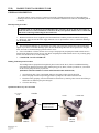
VANG BRACKET ON MAST
•
•
Vang is pinned on the top hole of the toggle of the vang bracket.
A single swivel block is shackled to the lowest hole of the toggle on the bracket.
BENETEAU 323
Apr. 01, 2004
rev 00
Page 40 of 85
RUNNING RIGGING SPECS
ITEM PART
No.
(6 digit)
024173
REV
QTY
00
2
DESCRIPTION
MAKE & TYPE
JIB SHEET
LANCELIN
COL.
TERMINAL 1
TERMINAL 2
BLACK
WHIPPING
WHIPPING
NOTES
DIA
LENGTH
mm
FEET
IN
10mm
10000
32
9
11 /
16
112758
00
1
MAINSHEET
SAMSON LS
GREY
SOFT EYE
WHIPPING
3/8"
18000
59
0
5/
8
112761
00
2
SAMSON LS
WHITE
SOFT EYE
WHIPPING
5/16"
6000
19
8
3/
16
112599
00
1
MAINSHEET
TRAVELLER
CONTROL LINE
GENNEKER
HALYARD
SAMSON LSTC
RED
WHIPPING AND
LOOP
3/8"
30000
98
5
1/
16
112572
00
1
GENNEKER TACK
STROP
SAMSON LSTC
BLACK
SOFT EYE
SNAPSHACKLE
W2475
BURNT
BURNT
3/8"
7000
22
11
9/
16
112580
00
2
GENNEKER SHEET SAMSON LSTC
- twin sheet system
RED
BURNT
BURNT
3/8"
22000
72
2
1/
8
00
1
JIB HALYARD #1
GLEISTEIN
TASMANIA
BLUE
BURNT
10mm
29200
95
9
9/
16
00
1
MAIN HALYARD classic mast
GLEISTEIN
TASMANIA
RED
BURNT
10mm
30300
99
4
7/
8
00
1
MAIN HALYARD roller furling mast
GLEISTEIN
TASMANIA
RED
BURNT
10mm
30300
99
4
7/
8
00
1
MAIN BOOM
TOPPING LIFT
GLEISTEIN
TASMANIA
YELLOW
BURNT
6mm
27300
89
6
13 /
16
GLEISTEIN
TASMANIA
GLEISTEIN
TASMANIA
GLEISTEIN
TASMANIA
GLEISTEIN
TASMANIA
GREEN
KNOT + 7MM
ZSPAR 3639 D
SHACKLE
KNOT + 7MM Zspar
3639
D
shackle
KNOT + 6MM
ZSPAR 56
D SHACKLE
KNOT + 6MM
ZSPAR 3212
D SHACKLE
BURNT
BURNT
8mm
12000
39
4
7/
16
BLUE
BURNT
BURNT
10mm
18000
59
0
5/
8
BLACK
BURNT
BURNT
10mm
15600
51
2
3/
16
BLACK
BURNT
BURNT
8mm
3000
9
10
1/
8
BLACK
BURNT
8mm
11000
36
1
1/
16
RED
KNOT +
ZSPAR 253
SINGLE+BECKET
BLOCK
BURNT
BURNT
10mm
19600
64
3
5/
8
BLUE
BURNT
BURNT
10mm
27400
89
10
3/
4
00
1
VANG LINE
00
1
MAIN RF
INHAUL LINE
MAIN RF OUTHAUL
LINE
OUTHAUL AFT
LINE - classic mast
00
1
00
1
00
1
OUTHAUL FWD
GLEISTEIN
LINE - classic mast TASMANIA
00
1
00
1
REEF 1 classic mast
REEF 2 classic mast
BENETEAU 323
Apr. 01, 2004
rev 00
GLEISTEIN
TASMANIA
GLEISTEIN
TASMANIA
Page 41 of 85
1. standard - supplied
with vang.
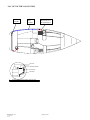
XIV)
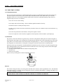
FRESH WATER SYSTEM
The fresh water system supplies the sink in the galley, the wash basin and shower in all of the heads, and the transom
shower. This system is pressurized by an electric pump. There is a filter between the water tank manifold and the pump. It is
necessary to check and clean this filter regularly.
Never run an electric pump when the tank is empty. It may burn out the pump.
OPERATION.
1.
2.
3.
4.
5.
•
•
•
•
•
BENETEAU 323
Apr. 01, 2004
rev 00
Fill the water tanks. (SEE DECK SECTION FOR WATER FILL LOCATIONS)
Select the tank for use at the valves on the manifold.
Turn on the fresh water pump at the panel.
Open all taps and bleed off any trapped air in the lines until the water runs clear with no sputtering.
Close all taps and the pump will turn off when it reaches operating pressure. If the pump continues to cycle
check all fittings for leaks.
Never fill up with water and diesel at the same time if the filling points are close to each other, to avoid the
risk of contaminating one liquid with the other.
Similarly, avoid risk of contamination by never handling a product that might cause pollution close to the
deck fill while taking on water.
If unused for a long time, the tanks and pipes need to be flushed with a solution of acetic acid (solution of
vinegar and water).
The sink and washbasins are drained through their own thru-hull valves; these should be kept closed when
the fresh water system is not in use.
Do not force hosepipe nozzle down the fill pipe as a high back pressure could occur. Check the
vent/overflow fitting to avoid over filling.
Page 42 of 85
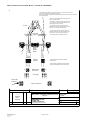
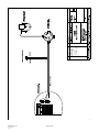
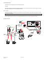
LAY OUT OF THE FRESH WATER SYSTEM
ALL VERSIONS
FRESH WATER FILL AND TANK CIRCUIT
GALLEY SINK
DECK FILL
AND VENT
BOW TANK
160L = 42 US gal.
TRANSOM
SHOWER
WATER HEATER
23L = 6 US gal.
FRESH WATER PUMP
AND FILTER
BENETEAU 323
Apr. 01, 2004
rev 00
WASHBASIN /
SHOWER
FRESH WATER
PUMP & FILTER
PUMP STATION
BEHIND STBD SETTEE
Page 43 of 85
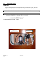
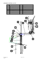
XV)
BILGE PUMP SYSTEM
OPERATION
The pump is normally automatic but can be controlled manually from a switch on the main 12V panel. There is also a
reset push button on the panel. Be sure to clean the filter between the pump and sump carefully, at regular intervals. To
clean the filter, unscrew the body and wash out the filter screen.
WARNING! BE CAREFUL NOT TO WASH THE O-RING SEAL OUT OF THE FILTER.
Make sure the bilge pump system is in good working order before you put out to sea.
Acquaint yourself with the way the bilge pump system of your boat works:
-
Locate the manual bilge pump and the handle.
Locate the switch of the electric bilge pump.
(See the lay out drawing of the system - next page)
PUMP STATION
BEHIND STBD SETTEE
BENETEAU 323
Apr. 01, 2004
rev 00
BILGE / SHOWER
PUMP AND FILTER
Page 44 of 85
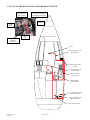
LAY OUT OF THE BILGE PUMP / SHOWER DRAIN SYSTEM
3-WAY
VALVE UNDER
SINK IN HEAD
TURN HANDLE
COUNTERCLOCKWISE
FOR SHOWER DRAINING
FROM
SHOWER
FROM
SUMP
VALVE POSITION
FOR BILGE
DRAINING
TO
PUMP
SUMP
ELECTRIC BILGE PUMP
INTAKE HOSE
ELECTRIC BILGE PUMP
+ FILTER
MANUAL BILGE PUMP
INTAKE HOSE
BILGE / SHOWER
3-WAY VALVE
SHOWER DRAIN
INTAKE HOSE
ELECTRIC BILGE PUMP
DISCHARGE HOSE
MANUAL BILGE PUMP
DISCHARGE HOSE
MANUAL BILGE PUMP
BENETEAU 323
Apr. 01, 2004
rev 00
Page 45 of 85
BENETEAU 323
Apr. 01, 2004
rev 00
Page 46 of 85
XVI)
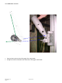
SEACOCKS AND THRU-HULLS
GENERAL DESCRIPTION
The thru hulls that are below the water line have 1/4-turn valves, which must be opened only during use. The quarter-turn
valve is open when the lever is in line with the pipe, and closed when it is at right angles.
Safety - Maintenance
Take special care to see that these valves are well maintained, have a good seal and work smoothly. Have a wooden
tapered plug, of correct diameter at hand, so that they can be plugged on the outside if, for instance, a seized valve has to
be dismantled, or lubricated.
After hot water has been run through a pipe for the first time, check the tightness of all the clamps.
NOTE: THESE RECOMMENDATIONS ALSO APPLY TO THE COOLING SYSTEM OF THE INBOARD ENGINE
Close all the seacocks when you leave the boat.
The toilet is situated below the waterline; get into the habit of systematically closing the seacocks after each use.
Make sure that all seacocks, which are not used, are closed before you put out to sea.
Opening and closing of the seacocks
Open
Closed
REF
1
2
3
4
5
6
7
8
9
10
11
12
13
BENETEAU 323
Apr. 01, 2004
rev 00
DESCRIPTION
Head Discharge
Head Intake
Washbasin Discharge
Optional Waste Tank Discharge
Galley Sink Discharge
Engine Cooling Water Intake
Ice Box Draining
Stern Tube Cooling Intake Valve
Speed/Log, Depth Sounder Thruhulls
Electric Bilge Drain
Manual Bilge Drain
Exhaust
LPG Locker Drain (on transom)
Page 47 of 85
SEACOCK AND THRU-HULL LAY OUT
9
5
7
2
3
4
1
8
6
10
11
12
13
BENETEAU 323
Apr. 01, 2004
rev 00
Page 48 of 85
XVII)
MARINE TOILET & HOLDING TANK
GENERAL DESCRIPTION
The marine sanitary system consists of a marine toilet (head), a holding tank and a series of thru hull intakes,
discharges and valves to control the intake of water into the head to flush the bowl either into the holding tank or
overboard.
Head Operating Procedure
The marine heads on your Beneteau are installed below the water line, all valves must be closed after use
and the selection lever on the head must be returned to the dry bowl position. Failure to do so could result
on the bowl overflowing and flooding the boat with water.
1. Read the instructions for use supplied by the head manufacturer and the precautions marked on the pump.
2. Before use, make sure that the water supply thru-hull valve is open and the Y-valve is selected for discharge
into the holding tank.
NOTE: BY LAW YOU MUST USE A HOLDING TANK IN ALL US WATERS.
3. Check with local authorities for regional laws governing your area before selecting the overboard discharge
option. If you choose overboard discharge option, be sure the discharge thru-hull valve is open before using the
head. Select the overboard discharge position on the Y-valve.
4. Select "Flush Bowl" with the selection lever on top of the pump body and pump the handle until the bowl is
flushed clean. Return the selection lever to "Dry Bowl" and pump the handle until the bowl is dry. Limiting pump
strokes will maximize the use of the holding tank.
5. CLOSE THE VALVES AFTER USE.
Holding Tank Pump Out Procedure
The holding tanks are pumped out through deck plates located on the deck. (Unless an additional draining
option has been installed; macerator pump, manual pump, gravity drain) Consult your dealer or your marina
for the closest pump out facility in your area.
(SEE DECK SECTION FOR LOCATION OF PUMP OUT DECK FITTINGS)
1.
2.
3.
4.
Open the deck plate with a winch handle and insert the pump out hose into the deck fill,
Follow the pump out stations operating procedure to pump all of the effluent from the tank.
Flush the tank by pumping water thru the head into the tank or by inserting a hose into the deck fitting to
add fresh water and then pump the tank again.
Close the deck fitting.
Operation of three-way valve for toilets
TO WASTE
TANK
CLOSED
OVERBOARD
CLOSED
CAN BE PADLOCKED
AND/OR SEALED IN
EITHER POSITION
FROM
TOILET
FROM
TOILET
BENETEAU 323
Apr. 01, 2004
rev 00
Page 49 of 85
WASTE TANK LOCATION
WASTE TANK
50L = 13 US gal.
BENETEAU 323
Apr. 01, 2004
rev 00
Page 50 of 85
MACERATOR (OPTION)
OPERATION
This macerator waste tank drain system is designed as an independent draining system for the waste tank.
The 12V macerator pump, pumps out the waste tank via a pick-up tube mounted in the waste tank in less than 3 minutes using
an intermittent switch and its own thru-hull.
The system has a breaker on the 12V panel to provide power, but the system is operated by a momentary switch in the head.
This system can be operated only in an unrestricted discharge area.
The pump must not run dry for longer than 15 seconds as the pump impeller will fail due to excess heat.
NOTE: BY LAW YOU MUST USE A HOLDING TANK IN ALL US WATERS.
Check with local authorities for regional laws governing your area before electing to discharge waste using this option.
Be sure to open the valve at the thru-hull before use and make sure it is closed after the tank has been drained.
ORANGE
BLACK
MACERATOR PUMP installed under sink
Junction box near by the pump
10A
10A
NAV LTS
8
DC VOLTS
ANCHOR
LT
BILGE PUMP
16
5A
10A
FRESH
WATER PUMP
BATTERY CONDITION
5A
10A
STEAMING
LT
BENETEAU
15A
BATTERY TEST
REFRIG
5A
GAS VALVE
CABIN LTS
10A
10A
SPARE
10 AWG Red
INSTRUMENTS
10 AWG black
Neg. from Wago block
Install the breaker 20A on the empty spot.
Add label macerator
Momentary switch to be installed
to the right of the light switch
under the sink
20A
10 AWG Red from panel
Do not use S1 (16AWG) .Wire the
10 AWG-red wire directly to the breaker
R
DESCRIPTION
DATE
Scale:
FH8
DRAWING
Material:
Dimension N/A
Gen.Tol:
B323
Macerator pump
Design Date:
10/16/03
By: P.LG
BENETEAU USA
P.O. Drawer 1218
Marion, SC 29571
(803) 423-4201
Part No.
Macerator 12v
THIS DOCUMENT IS - PROPRIETARY AND REPRODUCTIONS MUST BE AUTHORIZED BY BENETEAU
- DRAWN BY BENETEAU - SPECIFIED AND DESIGNED BY PRODUCT MANUFACTURER.
BENETEAU 323
Apr. 01, 2004
rev 00
Page 51 of 85
BENETEAU 323
Apr. 01, 2004
rev 00
Page 52 of 85
2 DI SCHARGE THRU- HUL L S
WASTE TANK DI SCHARGE:
DECK OR EL EC. MACERATOR OVERBOARD
MANUAL TOI L ET DI SCHARGE:
OVERBOARD OR WAST E TANK
MANUAL
TOI L ET
TOI L ET
I NTAKE
THRU- HUL L
MACERATOR
PUMP
WASTE
TANK
DI SCHARGE
THRU- HUL L
T OI L ET
DI SCHARGE
THRU- HUL L
Gen.Tol.:
WASTE TANK
N°: ZIT --- (I50+I59)
R00
Design Date :08/08/2000
BADB
By :
Approved Date:
By :
Weight :
Kg
THIS DOCUMENT IS - PROPRIETARY AND REPRODUCTIONS MUST BE AUTHORIZED BY BENETEAU - DRAWN BY BENETEAU - SPECIFIED AND
DESIGNED BY PRODUCT MANUFACTURER.
Tel. (843) 423-4201 - Fax. (843) 423-4912
1313 HIGHWAY 76 WEST
PO DRAWER 1218 , MARION,SC 29571
USA INC.
TANK SYSTEM DECK+MACERATOR
DISCHARGE 2 THRU HULLS
Visa :
VENT
BENETEAU USA MAN.TOILET+W ASTE
Scale:
Dimension in mm :
R DESCRIPTION By DATE
CAUTION
CAO
DRAWING
Material :
3 - WAY
VAL VE
WASTE TANK
PI CK- UP T UBE
DECK PUMP- OUT
XVIII)
ELECTRIC SYSTEMS
12V ELECTRIC SYSTEM
12 Volt Distribution Panel
The 12V power from your batteries is distributed throughout your boat via a distribution panel. This panel separates the
current into separate circuits. Each circuit is protected by an individual breaker switch which allows you to turn the
individual circuits on or off as needed at the panel. Each breaker switch has an individual amperage rating which it is
designed to trip at in case it is overloaded.
Never work on a live electric fitting.
Never tamper with an electric fitting. Call in a technician qualified in marine electricity.
The batteries must be carefully and safely stowed.
In order to prevent a short circuit between the battery terminals, do not store conductive objects near the batteries (e.g.
metal tools, ...)
Never alter the specifications of the breakers, which protect against overload.
Never fit or replace the electric materials or appliances with components, which exceed the system amperage.
Terminal Block
The panel is wired to the boat thru a wago block strip. The boat's wiring harness and the panel are connected together at
the wiring block strip using a series of plugs from each that snap onto opposite sides of the wiring block strip. Each of the
boats positive 12V circuits connect to it's circuit breaker in the panel this way, i.e.: Wire #7 "Deck Light' connects across
the wiring block to circuit breaker #7 on the panel. The negative side of the circuits lead to a common ground.
Each strip on the wago wiring block is an individual block mounted side by side on a frame to form the wiring block strip.
These individual blocks can be connected to the blocks on either side of it to create a larger circuit as in the saloon lights.
Wires are inserted into the block by:
1. Inserting a small screwdriver into the inside hole and pressing down.
2. Insert the wire.
3. Remove the screwdriver
Remove wires by inserting the screwdriver and pulling out the wire.
Batteries
The amount of charge the battery is receiving can be checked on the voltmeter, which is graduated in volts. This should be
done when the battery is cold (has not been recharged or used for several hours beforehand). A reading of less than 11.5 V
means that recharging is necessary.
WARNING! NEVER OPERATE ISOLATING SWITCHES WHILE THE ENGINE IS RUNNING - DOING SO
COULD DAMAGE THE ALTERNATOR DIODES AND REGULATOR BEYOND REPAIR.
BENETEAU 323
Apr. 01, 2004
rev 00
Page 53 of 85
12V Charging System
The batteries must be recharged by one of the following systems:
Alternator
A belt drive alternator is mounted to the engine which produces 12V as needed by the batteries when the engine is running.
The output of the alternator is wired to the battery switches.
Battery Charger
A marine battery charger is wired into the 110V shore power system. This charger converts the AC dock power to 12V DC
and feeds it to the batteries.
WARNING! DO NOT OPERATE THE CHARGER WHEN THE ENGINE IS RUNNING.
The battery charger is completely automatic; refer to the charger's manual for complete details. To charge the batteries
using the charger: plug in the shore power cord and turn the charger breaker on at the 110V shore power panel.
Electricity Lay Out
Eng.room blower
From Harness +181 Red
87
From Harness
-181 Blk
86
ON/OFF
85
30
12V PANEL
_
+
T1
Pos.red
Yanmar ”B” panel
From Harness +18
241+
Relay behind
engine panel.
Use rubber boots to
cover wire connections.
241White
Light
switch
On/off
swith
Starter
# 24 R/B plug
from Harness
red
black
Big Red
Main pwr
BATTERY
SWITCHES
House
Engine
Negative
Use rubber boots to
cover wire connections.
B+
Fuel tank
55A
Alternator
ENGINE
300A
FUSE
House BATTERY
BENETEAU 323
Apr. 01, 2004
rev 00
Engine BATTERY
Page 54 of 85
12v Panel
OFF
OFF
OFF
OFF
OFF
OFF
OFF
OFF
OFF
OFF
BREAKER
AMPERAGE
BENETEAU 323
Apr. 01, 2004
rev 00
Page 55 of 85
Wago Block
Loose wires
+4
+/- 271 , 272,273,274
Negative DECK
ELECTRICAL
PANEL
Negative HULL
12V NEG. PANEL
FRIDGE
11
+99
12V POS.PANEL
1/10
1/10
1/10
1/10
T1
NAVIGATION LIGHT-1/10
T1
FRESH WATER PUMP-13
BILGE PUMP-14
13
14
16
16
9
10
1
T1
13
14
162
165
Hull
G1
G2
Z1
Z1
Z2
Z3
Z4
5
6
7
30
30
30
30
30
30
30
30
30
30
30
GAS VALVE-17
STEREO-Z1
VHF-Z2
ANCHOR LIGHT-5
STEAMING LIGHT-6
INTERIOR LIGHTS-30
DESCRIPTION
R
DATE
B323
Wago block hook-up
BENETEAU USA
0000
0000
BENETEAU 323
Apr. 01, 2004
rev 00
27-98
VHF
Deck
5
67
42
49
53
54
56
57
60
61
66
I
Deck
VISA
Material:
DIMENSION:
TOL GEN :
FH8
DRAWING
17
P.O. Drawer 1218
Marion, SC 29571
(803) 423-4201
DATE : 9/29/03
BY : P.LG
029257
Part No:
111386
THIS DOCUMENT IS - PROPRIETARY AND REPRODUCTIONS MUST BE AUTHORIZED BY BENETEAU
DRAWN BY BENETEAU - SPECIFIED AND DESIGNED BY PRODUCT MANUFACTURER.
Page 56 of 85
12v Harness Layouts
Hull Harness Layout
T1
CH0
CHM
CHS
99
24
M1
M2
165
165
11
60
98
9
181
17
M1
24/241
274
S54
S162
CH0
CHM
CHS
M2
98
3.300
TAC
14 13
105°
Tinned
14
14x2
R/B
13
14x2
R/B
3.300
R/B
14.100
FRIDGE
R
6.700
12v BLOWER-Bat SW TO panel
BILGE PUMP
WATER PRESSURE
11
8x2
18
14x1
181
14x2
165
14x2
98
16x2
R/B
11.000
9
16x2
R/B
10.100
54
16x2
R/R
7.200
274
16x2
R/B
7.600
17
16x2
R/B
7.100
PROPANE SOLENOID
STBD AFT FUEL TANK -GAUGE
4.300
3.200
15.100
13.500
R
B
R
B
24
16x2
R/B
5.600
241
16x2
R/B
0.400
M3
8x1
G/Y
9.500
M2
8x1
G/Y
4.600
M1
8x1
G/Y
270
16X2
R/B
Not by the panel
12v BLOWER-PANEL TO BLOWER
FRIDGE DRAIN PUMP
12V INSTRUMENTS
COMPASS LIGHT
STBD AFT BATH CEILING LIGHT
ot by the panel STBD OUTSIDE SPEAKER
12V TO FUEL TANK GAUGE
Not by the panel
GROUNDING -AC panel to engine
GROUNDING- DECK FILLER TO TANK
3.900
Not by the panel
9,800
Not by the panel
GROUNDING -TANK TO ENGINE
Constant power -stereo
CHS
6x1
R
7.400
Not by the panel
BATTERY CHARGER -ENGINE
CHM
6x1
R
7.400
Not by the panel
BATTERY CHARHER -HOUSE
Not by the panel
6x1
B
7.400
T1
16x1
R
9.900
162
14x2
99
6x2
R/B
9.900
60
14x2
R/B
9.900
105°
Tinned
L . (m)
Code
CH0
WIRE.
#
5.800
R
SIZE AWG COLOR
BATTERY CHARGER -NEGATIVE
ENGINE BATTERY TEST
OUT WITH 14+
SHOWER PUMP STBD HEAD
12V MAIN PANEL
COCKPIT 12V OUTLET
NOTE
DESIGNATION
VISA
DESIGN date :
Beneteau 323
HULL Harness - 2C1T
C
B
A
Ind
Add 165 sw,del 9,98 modif.
Add 165.17.M3.270
Add 18/181
MODIFICATIONS
1/23/04
12/17/03
12/03
DATES
Apr. 01, 2004
rev 00
P.LG
B 323 B6
BENETEAU USA
P.O. Drawer 1218
Marion, SC 29571
(803) 423-4201
This document is proprietary an d reproduction must be authorized by Beneteau-
BENETEAU 323
BY :
09/25/03
Page 57 of 85
Page 2/3
N° : 062779
C
Deck Harness Layout
105°
Tinned
Not by the panel
STBD OUTSIDE SPEAKER
Not by the panel
PORT OUTSIDE SPEAKER
57
53
16X1
R/B
11.300
9.500
8.600
CST POWER RADIO MEMORY
55
16X1
R/B
2.400
60
14X2
R/B
1.300
14X1
R
2.800
R
B
274
16x2
R/B
273
16x2
R/B
270
16x1
R
0.100
Not by the panel
27
16x2
R/N
1.800
AT WAGO BLOCK
12V STEREO
279
16x1
R
0.100
Not by the panel
POWER ANTENNA
i
272
16x2
R/B
3.650
Not by the panel
STBD INTERIOR SPEAKER
VHF
Coax RG 8 X
271
16x2
R/B
6.650
Not by the panel
PORT INTERIOR SPEAKER
WIRE.
#
SIZE AWG COLOR
1.300
11.700
1.500
9
14x2
40
14x2
43
14x2
47
14x2
45
14x2
54
14x2
42
16x2
R/B
6.150
5.150
3.700
56
16x2
R/B
4.950
12x1
B
4.300
NEG.COMMON MAST
16x2
R
4.300
MAST LIGHTS
8
4,5,6,7
R/B
B
R/B
1.000
B
6.800
8.600
R
R
B
67
16x2
R/B
8.300
10
14x2
R/B
10.800
1
14x2
R/B
5.550
49
16x2
R/B
7.000
WIRE.
#
B
SIZE AWG COLOR
POS+ GO THRU CONNECTOR
L . (m)
12v TO SALON SWITCH
VHF coax
4.600
BATH CEILING LIGHT
CHART TABLE CEILING
BATH ABOVE SINK LIGHT
FWD CABIN CEILING LIGHT
R/B
COCKPIT OUTLET 12V
105°
tinned
GALLEY CEILING LIGHT
FWD CABIN STBD READING LIGHT
R
AFT CABIN PORT READING LIGHT
GALLEY CEILING LIGHT
Picked from 47
4.250
14x2
16x2
AFT CABIN STBD READING LIGHT
PICKED ON 53
SALON CEILING LIGHT
14.750
4.850
61
66
PORT AFT CABIN CEILING LIGHT
SALON CEILING LIGHT
REPRIS SUR 40
1.05
R/B
105°
tinned
COMPASS LIGHT
2.500
4.300
R
14X2
Picked from 66
FWD CABIN PORT READING LIGHT
STERN LIGHT
BOW -RUNNING LIGHT
105°
Tinned
Code
GALLEY FLUORESCENT
NOTE
DESIGNATION
L . (m)
Code
NOTE
DESIGNATION
VISA
VISA
DESIGN date :
Beneteau 323
Deck Harness - 2C1T
BY :
09/25/03
A
Move 10
MODIFICATIONS
12/03
DATES
P.O. Drawer 1218
Marion, SC 29571
(803) 423-4201
This document is proprietary and reproduction must be authorized by Benetea u-
BENETEAU 323
Apr. 01, 2004
rev 00
Beneteau 323
Deck Harness - 2C1T
B 323 B6
BENETEAU USA
Ind
DESIGN date :
P.LG
A
A
09/25/03
P.LG
B 323 B6
BENETEAU USA
Page 2/3
N° : 062780
BY :
Move 10
Ind
MODIFICATIONS
12/03
DATES
P.O. Drawer 1218
Marion, SC 29571
(803) 423-4201
This document is proprietary and reproduction must be au thorized by Beneteau-
Page 58 of 85
Page 3/3
N° : 062780
A
t
BENETEAU 323
Apr. 01, 2004
rev 00
Page 59 of 85
110V-220V Electric System
The shore power system consists of a marine power cord adapter plug mounted on the transom of the boat which is
connected to an 110V panel that distributes the 110V AC current to the outlets and appliances on your boat. The shore
power system is rated for a maximum of 30 AMPS; care must be taken to not overload the system.
WARNING! DO NOT WIRE OPTIONAL AIR CONDITIONERS TO THE SHORE POWER SYSTEM;
INSTALL A SEPARATE SERVICE AND PANEL.
The 110V panel consists of breaker switches which protect and turn the individual circuits on and off. The charger, hot
water heater and the 110V outlet circuit are on separate breakers.
Boats are fitted with a 110V/60Hz or a 220V/50Hz system. We advise you to follow these steps in order to avoid the risk
of electric shock and fire.
Do not work on a live fitting.
Connect the boat / shore supply cable to the boat before you plug it into the shore supply socket with the
breaker off. Turn the breaker on last.
Do not immerse the boat / shore cable socket.
Turn off the shore supply switch on board before you plug in or unplug the boat / shore supply cable.
Do not tamper with the connections of the Boat / shore supply cable. Use only compatible connections.
Never swim in a marina around boats connected to shore power. If necessary for maintenance unplug the boat
being worked on and surrounding boats.
WARNING! DO NOT OPERATE THE 110V WATER HEATER DRY.
110V Panel
30
AC MAIN
SHORE
REVERSED
POLARITY
15
WATER
HEATER
15
15
BATTERY
CHARGER
OUTLETS
UPM
Ultra panel marine, MIAMI,FL, USA
BENETEAU 323
Apr. 01, 2004
rev 00
Page 60 of 85
Location of 110V Outlets and Appliances
REF
1
2
3
4
5
6
DESCRIPTION
Shore Power Inlet
Main Breaker
Battery Charger
110V Outlet
Water Heater
110V Panel
IN DECK
IN HULL
2 CABIN
4
4
4
6
3 CABIN
4
4
4
5
2
1
BENETEAU 323
Apr. 01, 2004
rev 00
Page 61 of 85
3
LAY OUT OF THE CONDUITS
IN HULL
IN DECK
BENETEAU 323
Apr. 01, 2004
rev 00
Page 62 of 85
XX)
LP GAS SYSTEM
GAS STOVE
Your Beneteau is equipped with a propane stove and oven combination. This unit is located in the galley and is gimbaled
for your safety and comfort in a seaway. The stove is supplied by a storage bottle located in a self draining locker in the
cockpit. The pressurized gas is fed thru a regulator at the bottle which reduces the pressure and feeds the propane gas to a
12V solenoid valve. The solenoid is a remotely controlled valve which turns the flow of gas on and off from a switch
located at the 12V distribution panel. A pressure gauge is located before the regulator to check the gas system for leaks.
The boat is delivered without fire extinguishers. It is your responsibility to comply with the laws and
regulations of your country (Number, capacity, type and place of fire extinguishers).
We advise you to install an extinguisher less than 5 meters away from the center of each berth, less than 2 meters away
from the extinguisher aperture in the engine compartment, less than 2 meters away from any open flame device and less
than 1 meter away from the helm pedestal or cockpit. We advise a total capacity of the portable extinguishers reaching
8A/64B, each extinguisher having at least a 5A/34B capacity. The CO2 extinguishers shall be used to fight fires in the
galley and electric fires.
Do not install or store flammable materials above the stove (Curtains, papers, napkins, etc…)
Never leave the boat unattended when the LP gas appliances are in use.
The appliances, which use fuel, consume the oxygen within the cabin and release combustion products into the
boat. It is necessary to ventilate the boat when using the gas cooking appliances. Do not obstruct the air vents of the
boat.
Do not smoke or use an open flame when you are trying to locate a gas leak, change the gas bottle or work on
the gas system.
If you smell gas or find that the burners have gone out by accident, (although some appliance models cut off the
gas automatically if the flames go out) turn off the gas valves and ventilate the boat in order to get rid of any residual
gas. Find the cause of the problem before re-lighting the appliance.
Do not use cooking appliances to heat the inside of the boat.
Turn off the 12V solenoid and the valve on the cylinder when you do not use the appliances.
Do not obstruct the access to the gas system components, in particular the access to the valves (cylinders and gas
cooker).
The flexible hoses, which connect the gas cylinder at one end of the system and the stove at the other end, shall be
changed in pursuance of the regulations in force in your country. Only use hoses, which meet the safety standards of
your country.
Do not use the gas cylinder storage space to store other equipment.
Pay particular attention to keep in good condition the screw thread of the cylinder on which the regulator is attached.
Check the condition of the regulator every year and change it if necessary. Use a regulator identical to the one which
is fitted.
Make sure that the valve of the empty cylinder is turned off and disconnected from the system.
Do not use ammonia-based products to clean any part of the system or to discover a leak.
The LP gas system should be checked for leaks on a regular basis. See the manual provided with the stove for
instructions.
BENETEAU 323
Apr. 01, 2004
rev 00
Page 63 of 85
OPERATION
WARNING! ALWAYS LEAVE BOTH THE SOLENOID VALVE AND THE VALVE ON THE GAS BOTTLE
CLOSED WHEN THE STOVE IS NOT BEING USED.
1. Read and follow the instructions printed on the propane warning labels located at the appliance and
under the lid of the gas storage locker.
2. Be sure all burner and oven knobs are in the off position before attempting to operate the galley stove.
3. Activate the main 12V system and be sure the solenoid switch is in the off position.
4. Open the supply valves and test the system for leaks following the instructions on the locker warning
label.
5. Switch on the solenoid using the breaker on the 12V panel.
6. Light the appliance in accordance with the stove manufactures procedures. Generally each burner is lit
by turning the burner control knob to the lighting position and then pushing the knob in. A safety
thermocouple will keep the valve open as long as the burner remains lit. If the flame goes out it will stop
the gas flow to the burner.
Note: If the odor of gas is detected at any, time turn off all electrical and mechanical systems, extinguish any
open flames and immediately check for a propane leak. Propane is a heavy gas and may settle in the bilge
which represents an explosion and fire hazard.
BENETEAU 323
Apr. 01, 2004
rev 00
Page 64 of 85
LAY OUT OF THE GAS SYSTEM
LPG
Conduit
LPG
Conduit
Hose from stove
to regulating kit
LPG TANK
PIG TAIL HOSE
PRESSURE GAUGE
REGULATOR
SOLENOID
HOSE TO STOVE
PROPANE LOCKER REGULATING KIT AND LPG TANK
BENETEAU 323
Apr. 01, 2004
rev 00
Page 65 of 85
XXI)
STEERING SYSTEM
WHEEL STEERING
Wheel steering has become increasingly popular over the years in lieu of a tiller. Reasons for this preference
include more cockpit space, and ease of steering over a long cruise.
A typical wheel steering system remotely turns the rudder on your boat using a quadrant bolted to the rudder
post and connected to the wheel through a chain and cable system. A stop assembly allows approximately 90
degrees of travel, and prevents rudder over-travel which could damage the cable and chain assemblies.
Wheel Steering Operation
Wheel steering requires use in order to obtain familiarity with it. A feel for your boat will develop and a
sensitivity to conditions will increase your control.
NOTE: When backing under auxiliary power in reverse gear, it is necessary to maintain a hold on the
steering wheel the entire time. The rudder and steering wheel have a tendency to rotate with force if left
unattended while backing. This is due to the normally large area aft of the rudder post becoming the forward
area, thus creating an imbalance.
The rudder stop system is designed to produce a positive stop to prevent over-turning the mechanisms of the
steering system. It is not designed to absorb the potentially tremendous load of a rudder turning freely while
backing. INSPECT the rudder stops on a regular basis to ensure they limit rudder travel to the correct
amount; failure to limit rudder play may result in steering failure!
CAUTION! ALLOWING THE RUDDER AND WHEEL TO SPIN OUT OF CONTROL WHEN
BACKING MAY CAUSE SERIOUS DAMAGE TO THE STEERING SYSTEM, POSSIBLY
RESULTING IN A DANGEROUS LOSS OF STEERING CONTROL.
When leaving the boat at a mooring or slip, make sure the wheel brake is properly tightened. Do not allow
the system to free wheel when not in use as excessive wear or damage may result.
WARNING! DURING OPERATION THE PIVOTING STEERING UNIT SHOULD BE LOCKED
INTO ITS NORMAL OPERATING POSITION WITH THE STEERING WHEEL
PERPENDICULAR BOW TO STERN. DO NOT OPERATE VESSEL WITH THE STEERING
UNIT PIVOTED OUT OF THE NORMAL OPERATING POSITION.
Emergency Tiller
As a safety precaution on your Beneteau, an emergency tiller has been provided as a backup to the wheel
steering system.
NOTE: PRACTICE USING THE EMERGENCY TILLER AND BE SURE ALL CREW MEMBERS
KNOW THE LOCATION AND OPERATION OF THE EMERGENCY TILLER
Check at least once a year that the steering cables are properly tightened and lubricated.
To use the emergency tiller, remove the cover over the rudder stock by using a winch handle; insert the tiller into
the socket on the rudderstock. You may remove the steering wheel while using the tiller, to improve the tiller
handle clearance.
BENETEAU 323
Apr. 01, 2004
rev 00
Page 66 of 85
STEERING SYSTEM LAYOUT
REF
1
2
3
4
5
6
7
8
DESCRIPTION
Rudder
Spacer Ring
Lower Rudder Shaft Bearing
Rudder Tube
Upper Rudder Shaft Bearing
Retaining Ring
Quadrant
Rudder stop
REF
9
10
11
12
13
14
15
16
DESCRIPTION
Cap Over Rudder Stock
Steering Cable
Idler Sheave Box
Steering Chain
Steerer
Wheel Brake
Steering Wheel
Emergency Tiller
14
15
16
10
13
12
9
7
8
6
11
5
4
3
2
1
BENETEAU 323
Apr. 01, 2004
rev 00
Page 67 of 85
XXII
ENGINE
CUTLASS BEARING
The cutlass bearing is a water-lubricated rubber bearing that the
prop shaft rotates in. It is critical for the shaft to be perfectly
aligned through the bearing and mated to the engine coupling to
prevent premature wearing of the cutlass bearing.
STUFFING BOX
The stuffing box is a rubber seal around the prop shaft, which
allows the shaft to exit the hull and keep water out. Water is forced
into the stuffing box via a thru hull and vent tube for lubrication.
Once a year or every 200-engine hours grease the seal at "D" with
1cm3 of grease. The seal should be replaced every 500 engine
hours or every 5 years. See the manufacturer’s directions for more
details.
DIESEL OPERATION
Operation of the diesel engine includes preparation for starting, running, stopping, and securing the power
system after use. The following paragraphs are a general guide, with complete procedures being more
thoroughly covered in the engine manual.
ADDITIONAL CONTROLS
In addition to the control panel the following controls are associated with engine operation.
1.
Battery Switch - Although a part of the electrical system, this switch must be energized in the ON
position to provide power to the engine starter motor.
DO NOT OPERATE BATTERY SWITCHES WHEN THE MOTOR IS RUNNING!
2.
Throttle and gearshift controls are located at the helm station.
3.
Engine Stop Handle or Solenoid switch.
RUNNING THE ENGINE
Before Starting the Engine
Before you start the engine, make sure that the engine compartment bilge is clean and dry. If there is the
slightest presence of fuel in the engine compartment, you must not start the engine.
1.
Open the raw water intake thru hull valve.
2.
Check to be sure the fuel shut-off valve is open.
3.
Check the coolant level if the engine is fitted with a closed heat exchanger cooling system.
4.
Check the oil in the sump and gearbox (this should be repeated after a few hours running).
5.
Check the tension of the alternator drive belt.
6.
Move the lever to neutral, and open the throttle a little (the mechanism will differ depending on the
control box fitted).
7.
Turn on the black negative battery handle and the red handled engine battery switch.
BENETEAU 323
Apr. 01, 2004
rev 00
Page 68 of 85
Starting the Engine
Insert the ignition key and turn it to "ON" (and then to the intermediate preheat position if your boat's engine
has this system). A warning alarm will sound as you start up - the engine manual explains the meaning of
this alarm and its operation.
Press the starter button or turn the key, as appropriate, and release the button or key, as soon as the engine is
running CHECK THE ENGINE EXHAUST FOR COOLING WATER DISCHARGE,
IMMEDIATELY STOP THE ENGINE AND CHECK THE RAW WATER SYSTEM. IF NO
COOLING WATER IS DISCHARGED FROM THE EXHAUST. Let the engine run for a moment, and
then bring the throttle lever back to the idle position. After you engage the clutch, increase the engine speed
very gradually (it should take at least five minutes to reach cruising speed), because a diesel engine will
warm up only when it is under load.
Do not operate the starter for more than 10 seconds at a time. If the engine does not start, wait at least 30
seconds before trying again.
CAUTION! OVER CRANKING AN ENGINE WITH A WATER LIFT MUFFLER CAN CAUSE
DAMAGE! IF THE ENGINE DOES NOT START, CLOSE THE THRU HULL AND SEEK
ASSISTANCE.
Once engine has started, check that the warning lights for oil and coolant pressure have gone out, and that the
batteries are charging properly.
Check that the coolant water is circulating correctly, water should be either venting through the exhaust or
passing through the heat-exchanger return circuit, depending on the cooling system fitted.
CAUTION! NEVER OPERATE THE BATTERY CIRCUIT SWITCH OR THE IGNITION KEY
WHEN THE ENGINE IS RUNNING. THE RESULTING CURRENT SURGE WILL DAMAGE
THE ALTERNATOR DIODES.
Engage the clutch firmly but not harshly. Do not rev the engine hard. When shifting from forward to
reverse, or vice versa, the lever should be held in the neutral position for a moment before proceeding.
Shifting should be performed with RPM reduced to idle. Keep a regular watch to make sure that the coolant
water is circulating properly.
Stopping the Engine
To stop the engine:
1.
Place throttle/transmission lever in the idle/neutral position.
2.
Let engine idle for one (1) minute to allow it to cool down.
3.
Engage the engine kill button or handle until the engine stops.
4.
Turn the key to the "OFF" position.
CAUTION! DO NOT SWITCH BATTERY SELECTOR UNTIL THE ENGINE HAS COME TO A
COMPLETE STOP! THIS WILL PREVENT ALTERNATOR DIODE DAMAGE.
CAUTION! IF YOU CLOSE THE FUEL AND SEA WATER VALVES AFTER STOPPING THE
ENGINE, BE SURE TO RE-OPEN THEM BEFORE RESTARTING. FAILURE TO DO SO COULD
CAUSE ENGINE TO OVER-HEAT AND CAUSE DAMAGE TO THE PUMP IMPELLER OR
CAUSE FUEL LINES TO BECOME AIR LOCKED
FUELING
While employment of a diesel engine results in a greatly reduced fire hazard when compared to gasoline, it
should be remembered that diesel fuel is flammable, and that the employment of good fueling practices are
necessary. The following steps are provided as guidelines.
BENETEAU 323
Apr. 01, 2004
rev 00
Page 69 of 85
Before Fueling
1.
Extinguish all smoking materials and check the fueling area for other sources of spark or flame.
Remove if found.
2.
Shut off the engine and the electrical generator if one is aboard.
3.
De-energize all electrical equipment.
4.
Close all hatches and ports.
5.
Ensure that a fire extinguisher is readily available.
6.
Ensure that the proper (diesel, not gasoline) hose is about to be used.
WARNING! DO NOT FUEL DURING AN ELECTRICAL STORM. BESIDES THE OBVIOUS
HAZARD OF LIGHTNING, THE POSSIBILITY OF STATIC DISCHARGE IS GREATLY
INCREASED AT THE TIME.
Fueling
The diesel tank is filled thru a deck filler. (SEE DECK SECTION FOR FUEL DECK FILL LOCATION)
The tank is filled for the first time with the cock closed to calibrate the fuel gauge. During filling, put a funnel
with a filter in the deck filler hole, and watch the fuel overflow outlet. Useful tip: to avoid staining teak on the
deck with diesel oil, wash the deck with water beforehand, this will stop the oil from penetrating the wood.
While filling, note how much fuel corresponds to the markings on the gauge (remembering that a small amount
of fuel not consumed during the factory engine tests may remain in the tanks);
Gauge markings:
1/4
1/2 3/4
F
Note: ( number of gallons per mark) ____ ____ ____ ____
Always sail with your tanks as full as possible, both to avoid any contamination of the diesel oil with water
(due to condensation in the tank), and to prevent the injector pump running dry and needing re-priming.
Fuel that is stored outside the tanks (spare cans, jerrycans) should be kept and stored in a ventilated place.
Know exactly where the fire extinguisher aperture is located so you will be able to put out a fire breaking out in
the engine compartment.
After Fueling
Replace cover, clean up any spilled fuel. If any rags, etc. were used for this purpose, dispose of them ashore.
Check below decks for presence of fumes or fuel leakage. Check bilge, engine space, and main cabin.
WARNING! IF FUMES OR EVIDENCE OF LEAKAGE IS FOUND, DETERMINE THE CAUSE,
CORRECT IT, AND CLEAN UP ANY SPILLAGE BEFORE PROCEEDING.
Open all hatches and ports to ventilate the boat.
Switch on battery.
The engine should be started only when it is certain that no potentially hazardous condition exists.
Fuel Sanitation
The fact that a diesel engine does not require an ignition system can, and usually does, result in an engine
that is far superior to a gasoline engine with regard to dependability. Whether this is actually the case
depends greatly on cleanliness of the fuel that is supplied to the engine since the close tolerances required by
the engine's fuel delivery system make it extremely intolerant of any form of dirt or water contamination.
The engine is supplied with filters that prevent contaminants from reaching the engine where they could
cause damage, but a clogged filter, although providing this protection, can also stop an engine. Keeping the
filters free of dirt and water is an obvious answer to this problem, and the cleaning schedules set forth in the
engine manual will in most cases keep filters clean enough to prevent stoppage.
BENETEAU 323
Apr. 01, 2004
rev 00
Page 70 of 85
Bacterial Contamination
A factor that can cause additional problems is bacterial contamination of the diesel fuel. The bacteria
involved need both water and fuel to exist, and if present, will thrive in a fuel tank. As they multiply, they
form a filter-choking brown slime. Often their presence will not be known until rough weather churns up the
fuel tank causing clogged filters at a most inopportune time.
Keeping water out of the fuel will, of course, prevent the problem entirely, and while every effort should be
made towards this, such as obtaining fuel from reputable dealers, it must be remembered that a certain
amount of water due to normal condensation in the tank is to be expected.
Fuel Additives
Fuel additives or conditioners provide means of combating this problem. These additives break the water
down to a molecular level, dispersing it throughout the fuel and allowing it to pass harmlessly through the
fuel system. Various brands of this product are available at marine supply stores. As with all products of
this nature, the directions on the container should be carefully followed.
BENETEAU 323
Apr. 01, 2004
rev 00
Page 71 of 85
ENGINE LAY OUT
Fuel Tank
Fill
Fuel Tank
Vent
Throttle/Shift
Lever
Fuel Filter
Antisyphon
Valve
Air Vent
Throttle/Shift
Cables
Fuel tank
Fire Extinguisher
Port
Engine
Raw Water
Filter
Waterlock
Muffler
Exhaust
Thruhull
Stern Tube
Water Intake
Engine Water
Intake
House
Battery
Fuel Filter
Engine
Battery
Battery
Switches
Fuel Shutoff
Cable
Throttle/Shift
Cables
Fuel tank
Antisyphon
Valve
Engine
Engine
Battery
Raw Water
Filter
Exhaust
Thruhull
BENETEAU 323
Apr. 01, 2004
rev 00
Fuel Tank
Fill
Fuel Tank
Vent
Engine Control
Panel
in cockpit
Page 72 of 85
Water
Heater
Waterlock
Muffler
XXIII)
HANDLING
Contact your BENETEAU dealer for maintenance and repair of your boat. The dealer will advise properly, or will
supply you with the spare parts you need or the materials that are suited to your boat.
Have your boat hauled & serviced once a year.
POSITION OF LIFTING STRAPS AND CRADLE POSITION.
NOTE: POSITION DIMENSION IS FROM CENTER STANCHION
BENETEAU 323
1903
BENETEAU 323
Apr. 01, 2004
rev 00
Page 73 of 85
1687
XXIV)
MAINTENANCE OF YOUR BOAT
Your boat represents a sizable capital investment that needs special and regular care
Safeguarding your investment and looking after your own safety should persuade you of
the importance of careful and regular upkeep of your boat. The maintenance suggestions
in the following sections will help you with the basics. Always refer to the original
manufacturer's manual for specific guidelines on individual components.
NOTE: It is important to clean the bottom of your boat at least two or
three times a year.
General Hull Maintenance
• DO NOT SAND THE HULL WITH COARSE SANDPAPER.
• DO NOT USE SOLVENTS TO CLEAN HULL.
• DO NOT WASH WITH PRESSURE MACHINE USING WATER
WARMER THAN 95 DEGREES F. (35 degrees C.).
• DO NOT USE PRESSURE EXCESS OF 2175 PSI (150 BAR.) WHEN
USING A HIGH PRESSURE SPRAY WASH.
• DO NOT HOLD NOZZLE CLOSER THAN 4 INCHES (10 CM) TO
SURFACE OF HULL.
• DO NOT MACHINE SAND.
We believe the above points to be pertinent for all FRP boats.
GEL COAT
The gel-coat is vulnerable to any nicks and scratches it may get during maneuvering in
harbor and on a mooring. The best way to avoid them is to undertake maneuvering
calmly, after thinking out all the relevant factors (such as speed, current, wind, and the
layout of the harbor). Always have one of the crew ready to put out a fender at the right
place. When bringing in the anchor chain, back off or swing the boat round so as not to
rub the chain against the hull. Hold the anchor well clear as you bring it aboard so that it
does not scrape the stem: lay it on deck and lash it down at once, if only temporarily.
Never use dirty fenders.
Hose off the hull and deck as often as possible, with fresh water.
Before hosing down, remember to check that the hatch covers are closed; and it is wise not
to take on diesel oil or fresh water supplies while you are hosing off the hull.
After a few years, the gel coat may be re-polished, either with a lambs wool buffer and
polish, or by hand using a polish or similar product. Your yard will also be able to supply
you with special cleaning products for getting rid of stubborn stains.
BENETEAU 323
Apr. 01, 2004
rev 00
Page 74 of 85
MINOR GEL COAT REPAIRS
To fill in a scratch or small nick, order a Beneteau Gel coat Repair Kit with instructions
for use, from your dealer or obtain a small quantity of gel coat and catalyst.
Clean the affected area and rub it down with wet-and-dry sandpaper, then dry it off
thoroughly (use a hair-dryer if necessary). Mix the components of the gel coat, and fill the
scratch using a spatula avoiding any excess; cover with a sheet of cellophane. Once
hardened remove cellophane and rub down with very fine wet/dry sandpaper (grade 600 or
800), and finish off by polishing the new surface.
THE DECK AND DECK FITTINGS
Using a gentle liquid detergent, scrub all nonskid areas to keep them free of dirt.
Light-alloy sections (tracks, etc.) can be cleaned in the same manner.
The tiny spots of oxidation pitting that may appear on stainless steel parts are nothing to
worry about. Polishing will remove them.
From time to time, lubricate pulley blocks and sheaves, turnbuckles, tracks and travelers
with light grease or a water-repellent lubricant such as WD-40 or Triflow.
After a certain time at sea, your winches will need cleaning inside. They must be cleaned
out completely once a year. Follow the manufacturer’s instructions carefully.
When dismantling deck fittings, have a bowl close at hand for putting the parts in, and
circle the area with a rolled dishcloth, or the like, so that any screws or springs you drop do
not roll overboard. Use the lubricant recommended by the manufacturer before
reassembling.
Warning! Incorrect re-assembly can cause accidents. Note the order in
which parts are dismantled, which will make it easier to put them
together again later.
Acrylic plastic hatch covers and portholes should be rinsed off with fresh water and rubbed
over with a soft cloth soaked in liquid paraffin.
BENETEAU 323
Apr. 01, 2004
rev 00
Page 75 of 85
THE RUDDER
Once a year, check steering gear. If necessary renew any parts (bushings, glands, etc.)
that are worn. Lubricate the steering chain and cable and or gears.
Never lubricate Nylon, Ertalon or Teflon bushings, with either oil or grease, use only WD40.
If you have wheel steering, maintenance should be in accordance with the manufacturer's
recommendations.
Make regular checks on all the clamps, the condition of the quadrant, the cables or push
rods, guide sheaves and the chain in the column to the wheel.
Make regular checks of the steering end stops to ensure they are adequately stopping the
rotation of the rudder, this is important for direct drive push rod systems. Over rotation of
the rudder could cause a steering lock up.
INTERIOR WOOD
Repairs to interior varnished surfaces are very challenging to accomplish. They should be
attempted by skilled professionals.
The internal woodwork used in most of our boats is varnished. This should be regularly
rinsed off with fresh water and a little liquid detergent, then polished with a chamois
leather.
Should the woodwork become damaged, gently rub it down with very fine sandpaper and
touch it with several coats of the varnish. Your dealer should be able to order a Beneteau
touch up kit. When this is dry, rub it down with a very fine wet-and-dry sandpaper (grade
800 or 1000) and finish off with polish (or a silicone spray) or wax.
ELECTRICAL SYSTEMS
It is essential for an electrical system to have a battery in sound condition to function
properly. The following are some of the things to maintain a battery in the best condition.
•
•
•
Keep the battery clean and the terminal posts well greased.
Keep the battery electrolyte checked regularly
Keep the battery fully charged.
If you have to leave your boat unused for more than a month it is best to leave your
batteries with your yard so that they can be kept charged. Keep a suitable charger onboard
so you can recharge your batteries at dockside without having to turn on the engine.
If you have an inboard engine, check the condition and tension of the alternator drive belt.
From time to time, spray a little WD-40 or something similar on all the connections to the
control panel, terminal boxes and lamp sockets. Make sure that cable grommets are
watertight; smear them with Vaseline so that they do not dry out and deteriorate.
BENETEAU 323
Apr. 01, 2004
rev 00
Page 76 of 85
BATTERY MAINTENANCE
Make sure that the level of the electrolyte is always at least 1/2" above the top of the plates.
This level can change suddenly, due to evaporation in an overheated bilge.
WARNING! THE ELECTROLYTE IN A BATTERY IS A SOLUTION
OF SULFURIC ACID. IF ANY SHOULD ENTER THE EYES, RINSE
IMMEDIATELY WITH LARGE AMOUNTS OF FRESH WATER,
AND SEEK MEDICAL ATTENTION. ELECTROLYTE SPILLED ON
SKIN SHOULD BE RINSED WELL WITH FRESH WATER. EVEN
SMALL AMOUNTS OF ELECTROLYTE SPILLED ON CLOTHING
WILL DESTROY THE CLOTHING.
If the level is low, fill the battery with distilled water and nothing else. The level of
acidity (i.e. the relative density of the electrolyte) should also be checked from time to
time.
CAUTION! USE ONLY PURE DISTILLED WATER TO REPLENISH
ELECTROLYTE LEVELS. THE WATER FROM MANY CITY
WATER SUPPLY SYSTEMS IS UNSATISFACTORY FOR BATTERY
USE.
Keep battery connections clean and tight. A cup full of strong baking soda solution and a
toothbrush will clean corrosion from the terminals and neutralize any spilled acid (do not
allow any of the solution to enter the battery cells). A coating of petroleum jelly or
silicone grease on the battery terminals will inhibit corrosion.
WATER SYSTEM
Check all joints regularly for leaks. Keep the tank(s) filled. If, however, you have to
leave the boat unattended for several months, disconnect the water lines, purge them, and
rinse them thoroughly with vinegar and water so that they do not form foul-smelling
deposits.
Important: If the electric pump continues running when all the taps are closed, switch off
the power supply at once and check the water system to find and overcome the leak that is
causing this.
Check the thru-hulls, seacocks, connectors and hose clamps regularly. Make sure the
seacocks turn freely.
MARINE HEAD
Maintenance consists of regularly pumping the system out with fresh water and leaving the
holding tank empty whenever possible.
Check the thru-hulls, seacocks, connectors and hose clamps regularly. Make sure the
seacocks turn freely.
BENETEAU 323
Apr. 01, 2004
rev 00
Page 77 of 85
ENGINE
Whether maintenance of the power system is to be performed by the owner or delegated to
a mechanic, it is the owner who must first initiate any action that is to take place. He must
either perform the maintenance or decide to call someone to do the job. A working
knowledge of the power system is essential in the first case, and preventive maintenance
desirable in the second. The engine manual is, of course, the prime source for engine
information and should be consulted, preferably before the fact. The following paragraphs
are included as a supplement to cover any required maintenance procedures that are not a
part of the engine manual.
We have already stressed the points that are of importance for an engine to keep working
properly. It might be added that the engine compartment should be kept scrupulously
clean; check for any unusual oil or fuel leaks. Inspect all the electrical connections
frequently.
Drain the bowl of the fuel/water separator at regular intervals to lessen the chance of water
damage to your engine’s fuel system. Keep fuel tanks filled.
Inspect the engine mounts and coupling for loose bolts regularly.
Check the oil and coolant levels everyday.
Check the alternator belt for the correct tension, keep a spare belt on hand.
Check all hoses and fuel lines for leaks regularly.
NOTE: Always have a spare set of sacrificial anodes on board, and regularly check those
that are already fitted for deterioration; they should be replaced when their size has been
reduced by half. The time this takes will vary with the waters in which the boat is used.
Water temperature, salinity, the presence of neighboring boats, the nature of the bottom
and the materials in the dock will all affect the life of your boat's anodes.
Order your spare anodes thru your dealer or from Beneteau Customer Service.
CALIFORNIA
Proposition 65 Warning
Diesel engine exhaust and some of its constituents are
known to the State of California to cause cancer, birth
defects, and other reproductive harm.
BENETEAU 323
Apr. 01, 2004
rev 00
Page 78 of 85
SAILS
Check the sails regularly, as the slightest wear in the stitching or at a reinforced part can
very quickly have dramatic consequences. Keep a small sail repair kit on board and a
book showing how to carry out minor work yourself until you can get the job done by a
professional sail maker.
Keep a special eye on points where the sails can chafe on the rigging or fittings turnbuckles, lifelines, shrouds, spreaders, etc.
Salt water and sunshine take their toll on sails. Whenever possible, rinse the sails in fresh
water and leave them stretched out (preferably on a lawn) to dry. Never dry a sail by
hoisting it and letting it flog in the wind; this will very quickly cause the sail to deteriorate.
Never fold and store a damp sail.
BENETEAU 323
Apr. 01, 2004
rev 00
Page 79 of 85
XXV)
WINTERIZING PROCEDURES
The end of the season is a good time for a complete inspection of all of the boat's systems.
It is easy to take shortcuts when decommissioning your boat but proper lay-up procedures
will ensure trouble free recommissioning in the spring.
The following sections are oriented towards hauling your boat for winter storage in a cold
climate, but they are also a good guideline as a lay-up procedure for your Beneteau in any
climate.
An improperly winterized boat will lead to costly repairs and extensive delays, we
recommend winterization by a competent yard or your Beneteau Dealer. The owner must
ensure that the boat is correctly winterized.
HAULING
Your Beneteau should be hauled for inspection and maintenance at least once a year; the
frequency of haul-outs may vary due to your local conditions and marine growth. A good
boatyard is seasoned in hauling and maneuvering boats on land, you may verify this by
checking to see that the weight of the hull is resting firmly on the bottom of the keel and
that even contact exists along the bottom of keel. Jack stands, or cradle uprights, are meant
to balance the boat and not to support its weight.
BOTTOM
Clean the yacht's bottom of any growth as soon as the boat is hauled. It is generally
preferred to wait until spring to paint the bottom. Use the following guidelines when using
a pressure washer:
MAXIMUM WATER TEMPERATURE TO BE 95° F. (35° C.)
MAXIMUM PRESSURE TO BE 2175 PSI (150 BARS) AT NO CLOSER
THAN 4"
CUTLASS BEARING
The shaft strut contains a rubber type cutlass bearing. At haul out, be sure the bearing
slots are clear and apply silicone lubricant or castor oil to the bearing to preserve its
suppleness. Replace the cutlass bearing if excessive wear is evident. Be sure to realign the
engine if the bearing is replaced. Bleed the prop shaft seal after re-launching
ZINC
Replace the sacrificial zinc before re-launching the boat.
BENETEAU 323
Apr. 01, 2004
rev 00
Page 80 of 85
FRESHWATER SYSTEM
This system is best winterized with one of the non-toxic antifreezes available for use in
boat and recreational freshwater systems. It is an easy method, which replaces fresh water
with a non-toxic antifreeze mixture.
Caution! Be sure to use non-toxic antifreeze in the fresh water system.
1. Allow the water in the water heater to cool, and open the pressure release valve on top.
Disconnect the hot and cold water hoses and allow the tank to drain either in a bucket
or into the bilge. Connect and clamp the hot and cold water hoses together using a
short length of 1/2" pipe in order to bypass the heater.
2. Mix the appropriate amounts of antifreeze and water, as directed on the label, to deliver
the degree of protection desired. Put 1-1/2 to 2 gallons of the solution into each water
tank.
3. Open both tank selector valves on the manifold.
4. Turn on the pump and open all fixtures until antifreeze runs through. Be sure to open
the hot water selector valve in order to supply antifreeze to the hot water hoses and
through the bypass loop.
5. At this point, the freshwater system should be completely protected by antifreeze
against freezing to a degree indicated by the strength of the solution placed into the
supply tanks.
6. New boats delivered have their freshwater systems filled with antifreeze as described
above, and are protected to -30 degrees F.
HEAD
Several days before completing haul-out procedures, fresh water should be allowed to
stand in the head unit to dissolve any salt accumulation in the hoses and pump. Remove
all water from the head. Special lubricants for the pump's internal mechanism are
available. Check with your marine hardware dealer for a recommended brand. Never put
oil, gas, kerosene, or alcohol in the head or they will ruin the internal valve.
Completely pump out all waste from the holding tank and pour in a cleansing, deodorizing
solution. If possible, allow this to sit in the tank overnight, then completely pump out and
drain the entire system. If antifreeze is used in the system, check in the manufacturer's
literature for the recommended type.
BENETEAU 323
Apr. 01, 2004
rev 00
Page 81 of 85
ENGINE
Winterization by a marine mechanic is highly recommended to ensure that your engine is
properly protected. Consult the Engine Owner's Manual for your specific engine's
guidelines for winterizing. Follow the instructions carefully to ensure the engine is
adequately protected. The general procedure is to replace raw seawater with an antifreeze
solution mixed to protect the engine in your local area and to check the heat exchanger side
to ensure that it contains an adequate antifreeze solution as well.
1. Prior to hauling the boat, run the engine to achieve normal operating temperatures in
order to open the thermostat.
2. Close the raw water intake thru hull and remove the hose from the valve hose barb.
3. Insert the intake hose in a bucket of antifreeze solution and run the engine briefly until
all raw water is flushed thru the exhaust system and only the antifreeze solution is
expelled from the exhaust.
4. Be sure the thru hull valve is opened after the boat is hauled.
FUEL SYSTEM
Consult your engine manual to clean any engine mounted fuel filters.
Drain any water from the bottom of the fuel/water separator.
The fuel tank should be kept full for winter storage with about 5% expansion room left at
the top. Empty fuel tanks encourage the formation of condensation.
BATTERIES
Clean battery terminals and cable ends thoroughly of any corrosion with a baking soda and
water solution, and apply a light protective layer of petroleum jelly.
Batteries should be fully charged before storage, and the fluid level maintained. Store
batteries in a warm, dry place. Do not store batteries directly on a stone or cement floor.
SEACOCKS
Open and drain all seacocks after boat is hauled. Open all seacocks for winter storage.
BILGE
Completely pump out bilge of any water and clean out any debris present. Bilge pumps
should be pumped dry and hoses disconnected, to ensure that no water is left in the system.
BENETEAU 323
Apr. 01, 2004
rev 00
Page 82 of 85
ICEBOX
Remove any remaining food from the icebox and wash down thoroughly with warm water
and detergent solution.
Odors can be removed with a baking soda and water solution, and an open box of baking
soda left in the icebox will continue to remove odors throughout storage.
Completely pump out any water from the bottom of the icebox and make sure pump is
completely dry of any water.
Leave icebox lid open during storage to allow ventilation.
STOVE
Depressurize the gas system and close all valves. Clean stove thoroughly. Remove fuel
tanks and clean to remove any salt accumulation from their surface. Wipe down stove and
tanks with a rag while applying a light layer of WD-40 or other lightweight, protective oil.
INTERIOR
Remove as much loose gear from the boat as possible and store in a clean dry place.
If cushions are left on board be sure they are dry and propped on edge to encourage
ventilation.
Rinse and dry all floorboards and store them on their edge to encourage ventilation.
Leave all lockers clean and open for ventilation.
COVERING THE BOAT
Cover the boat adequately during storage to prevent excessive weathering.
BE SURE THE COVER DOES NOT CHAFE BOAT.
Ventilation between the winter cover and the boat is required to avoid build up of
humidity.
CAUTION! DO NOT USE BLACK POLYETHYLENE AND DO NOT
SHRINK-WRAP THE BOAT BY TAPING TO THE HULL. ALWAYS
ASSURE GOOD VENTILATION.
SAILS
Remove the sails, clean following the sail makers recommendations and store in a clean
dry space.
BENETEAU 323
Apr. 01, 2004
rev 00
Page 83 of 85
MAST
The aluminum mast requires a minimum of care and maintenance. At the end of each
season it should be washed with a mild detergent and water solution, followed by a
complete rinsing with fresh water. Tie off all halyards and lifts, and inspect the mast
completely for scratches, cracks or stress marks. Apply paint or a clear lacquer to any
scratches found to prevent corrosion. Consult your dealer or a marine rigger if any
cracking or stressing of the aluminum tube is found.
Check all hardware on mast carefully for signs of corrosion, and check the tightness of the
fastenings. Masthead sheaves should show no signs of wear and should move freely.
Lubricate if necessary.
BENETEAU 323
Apr. 01, 2004
rev 00
Page 84 of 85
XXVI)
ENVIRONMENT
Do not pour oil overboard; use appropriate waste containers.
When you fill up the engine fuel tank, take all the precautions in order to avoid overflowing.
In the harbor, do not use the heads if they are not equipped with holding tanks.
The use of detergent contributes to the deterioration of the sea fauna and flora; choose entirely
biodegradable products for your cleaning operations.
Do not throw plastic bags overboard.
You love the sea, just as we do; therefore, help us to protect it and do not pollute it.
BENETEAU 323
Apr. 01, 2004
rev 00
Page 85 of 85