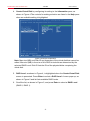
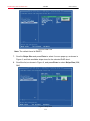
1
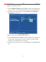
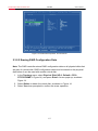
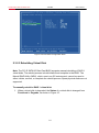
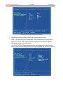
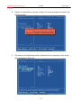
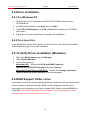
SATAIII PCI-E RAID Controller Card RC-230 User Manual SATAIII PCI-E RAID Controller Card - RC-230- User’s Manual Contents PACKAGE CONTENTS ......................................... 3 CHAPTER 1 INTRODUCTION TO HARDWARE .. 4 1.1 KEY FEATURES ....................................................................... 4 1.2 SYSTEM REQUIREMENT ........................................................... 5 CHAPTER 2 GETTING START ............................. 6 2.1 HARDWARE LAYOUT ................................................................ 6 2.2 HARDWARE INSTALLATION ........................................................ 6 2.3 CREATING AND MANAGING VIRTUAL DISK ................................... 7 2.3.1 CREATING VIRTUAL DISKS ............................................ 7 2.3.2 MANAGING VIRTUAL DISKS ......................................... 14 2.3.2.1 VIEWING PROPERTIES OF VIRTUAL DISK ............. 14 2.3.2.2 ERASING RAID CONFIGURATION DATA ............... 15 2.3.2.3 REBUILDING VIRTUAL DISK ................................ 16 2.3.2.4 DELETING VIRTUAL DISK ................................... 20 2.4 DRIVER INSTALLATION ............................................................ 21 2.4.1 FOR WINDOWS OS ................................................... 21 2.4.2 FOR LINUX 2.6.X ....................................................... 21 2.5 TO VERIFY DRIVER INSTALLATION (WINDOWS).......................... 21 2.6 RAID SUPPORT UNDER LINUX ............................................... 21 -2- SATAIII PCI-E RAID Controller Card - RC-230- User’s Manual Package Contents The following items should be found in your package: 1x Rosewill RC-230 SATAIII PCI-E RAID Controller Card 1x User Manual 1x Low Profile Bracket 1x Resource CD for RC-230, including: Drivers User Guide Note: Make sure that the package contains the above items. If any of the listed items are damaged or missing, please contact with your distributor. -3- SATAIII PCI-E RAID Controller Card - RC-230- User’s Manual Chapter 1 Introduction to Hardware Thank you for purchasing Rosewill’s RC-230 SATAIII PCI-E RAID Controller Card with 4 SATA ports and 2 eSATA ports. This board is a single-chip, PCI Express to four SATA Gen III 6Gbps channels host controller that brings server-class features to the desktop. This board enables the use of the industry’s newest and fastest hard drives at 6Gbps while providing backward compatibility to legacy SATA 1.5Gbps or 3Gbps drives. It uses the same cable and connectors as previous SATA generations to ease integration. Besides, PCI Express 2.0 double the bandwidth of the existing PCI Express bus for faster data throughput. It will enhance system performance for every type of computer user. It is also backward compatible with previous generation of PCI Express 1.0 technology. Using the onboard RAID firmware, the 4 SATA drives attached to this controller can be easily configured as 4 individual ports with no RAID or with RAID 0, RAID 1, RAID 10, HyperDuo. 1.1 Key Features Marvell Chipset Compliant with PCI-Experss Specification v2.0 and backward compatible with PCI-Express 1.x Compliant with Serial ATA Specification 3.0 PCI Express x2 interface, and compatible with PCI Express x4, x8 and x16 slots Supports communication speeds of 6.0Gbps, 3.0Gbps, and 1.5Gbps Hot plug and Hot Swap Supports Native Command Queuing (NCQ) Supports Port Multiplier FIS based switching or command based switching Max. 4 HDDs to PM for individual drive configuration Compatible with SATA 6G, 3G and 1.5G Hard Drives Support RAID function: RAID 0, RAID 1, RAID 10 and HyperDuo Supports 48-bit LBA, maximum HDD size can be support are up to 144,000TB. Supports ATA and ATAPI command and works with SATA Optical Drives. -4- SATAIII PCI-E RAID Controller Card - RC-230- User’s Manual OS support: Windows 8 (32/64 bit), Windows Server 2008 R2 (32/64 bit), Windows 7 (32/64 bit), Vista (32/64 bit), Windows XP (32/64 bit) Linux 2.6.x and higher kernel OS 1.2 System Requirement Computer that supports PCI Express x4, x8 or x16 slot Windows® XP/Vista/7/Server 2008 R2/8, Linux 2.6.x and above -5- SATAIII PCI-E RAID Controller Card - RC-230- User’s Manual Chapter 2 Getting Start 2.1 Hardware Layout Note: There are six SATA ports in PCI-E SATA 6G Card. We name these ports character A through F. Ports A to D are internal SATA ports and E & F are external eSATA ports. By changing the jumper setting on PCI-E SATA 6G Card allows you to select between external and internal ports to use. By default, port A, B, C and D are working. Jumper Settings JP J1-J4 J5-J8 Description Active Port 1-2 close Enable SATA Port A 2-3 close Enable eSATA Port E 1-2 close Enable SATA Port B 2-3 close Enable eSATA Port F Port C and D are always active. With different jumper setting you can active port A, B, E and F by referencing the above table. 2.2 Hardware Installation 1. Turn off the power to your computer. -6- SATAIII PCI-E RAID Controller Card - RC-230- User’s Manual 2. Unplug the power cord and remove your computer’s cover. 3. Locate to an empty PCI Express x4, x8, or x16 slot on the motherboard. 4. To install the board, carefully align the card’s bus connector with the selected PCI-E slot on the motherboard. Push the board down firmly. 5. Attach your internal devices to the PCI-E SATA 6G Raid Card. 6. Replace the slot bracket’s holding screw to secure the card. 7. Replace the computer cover and reconnect the power cord. 2.3 Creating and Managing Virtual Disk 2.3.1 Creating Virtual Disks This section describes the produce for creating virtual disks using the BIOS Configuration Wizard. To create a virtual disk: 1. In the Topology pane, scroll to HBA0: Marvell 0 and press Enter to select. A menu pops-up, as shown in Figure 1. Select Configuration Wizard and press Enter to begin creating the virtual disk. Figure 1 Configuration Wizard 2. Press Space to select/unselect a disk a disk, as shown in Figure 2. Use the arrow keys to scroll the list of free disks. -7- SATAIII PCI-E RAID Controller Card - RC-230- User’s Manual Figure 2 Select Free Disks Note: The PCI-E SATA 6G Raid Card supports the creation of RAID 0 and RAID 1 virtual disks comprising of exactly two SATA physical disks. PATA physical disks cannot be used to create RAID virtual disks. 3. After selecting the required disks, press Enter to continue, shown in Figure 3. Figure 3 Confirm Disk Selection -8- SATAIII PCI-E RAID Controller Card - RC-230- User’s Manual 4. Create Virtual Disk by configuring its setting in the Information pane, as shown in Figure 4.The controls for making selection are listed in the Help pane when an available setting is highlighted. Figure 4 Configure Virtual Disk Note: Max size (MB) and Disk ID are properties of the virtual disk that cannot be edited. Max size (MB) in the size of the RAID virtual disk as determined by the selected RAID Level. Disk ID lists the IDs of the physical disks comprising the virtual disk. 5. RAID Level, as shown in Figure 4, is highlighted when the Create Virtual Disk screen is presented. Press Enter to select a RAID Level. A menu pops-up, as shown in Figure 5 and list lists available RAID levels. 6. Scroll the list, as shown in Figure 5, and press Enter to select a RAID Level (RAID 0, RAID 1). -9- SATAIII PCI-E RAID Controller Card - RC-230- User’s Manual Figure 5 RAID Level Note: The default Level is RAID 0. 7. Scroll to Stripe Size and press Enter to select. A menu pops-up, as shown in Figure 6, and lists available stripe sizes for the selected RAID level. 8. Scroll the list, as shown in Figure 6, and press Enter to select Stripe Size (32K, 64K) Figure 6 Stripe Size -10- SATAIII PCI-E RAID Controller Card - RC-230- User’s Manual Note: The default size is 64 KB. 9. Scroll to Gigabyte Rounding and press Enter to select. A menu pops-up, as shown in Figure 7, and lists available stripe sizes for the selected RAID level. 10. Scroll the list, as shown in Figure 7, and press Enter to select Gigabyte Rounding (None, 1G, 10G) Figure 7 Gigabyte Rounding Note: The default setting for Gigabyte Rounding is 1G. 11. Scroll to Quick Init and press Enter to enable to disable quick initialization of the virtual disk. A menu pops-up, as shown in Figure 8, and lists available options for quick initialization of the virtual disk. 12. Scroll the list, as shown in Figure 8, and press Enter to select Quick Init (Yes, No). -11- SATAIII PCI-E RAID Controller Card - RC-230- User’s Manual Figure 8 Quick Init Note: The default setting for Quick Init is Yes. 13. Scroll to VD Name and the Default name is cleared for a new name, as shown in Figure 9. Type a new name and press Enter to confirm the selection. Figure 9 VD Name -12- SATAIII PCI-E RAID Controller Card - RC-230- User’s Manual 14. After configuring the virtual disk, scroll to Next, as shown in Figure 10. Press Enter to create the virtual disk. Figure 10 Create Virtual Disk 15. Please Y to select Yes, as shown in Figure 11, to confirm the creation of the virtual disk. The virtual disk is now listed in the Topology pane, as shown in Figure 12. Figure 11 Create Virtual Disk Confirmation -13- SATAIII PCI-E RAID Controller Card - RC-230- User’s Manual Figure 12 Virtual Disk in Topology Pane 2.3.2 Managing Virtual Disks This section contains the following topics: Viewing Properties of Virtual Disk Erasing RAID Configuration Data Rebuilding Virtual Disk Deleting Virtual Disk 2.3.2.1 Viewing Properties of Virtual Disk 1. To view the properties of a virtual disk, scroll to the Virtual Disk (VD 0: Default in Figure 13) in the Topology pane. The properties of the virtual disk are displayed in the Information pane when VD 0: Default is highlighted, as shown in Figure 13. -14- SATAIII PCI-E RAID Controller Card - RC-230- User’s Manual Figure 13 Virtual Disk Properties: Functional VD 2.3.2.2 Erasing RAID Configuration Data Note: The RAID controller stores RAID configuration data on all physical disks that are part of a virtual disk. RAID configuration data must be erased on the physical disk before it can be used with another virtual disk. 1. In the Topology pane, select Physical Disk (VD 0: Default > PD 0: ST3750330MS in Figure 14) and press Enter. A menu pops-up, as shown Figure 14. 2. Select Delete to delete the virtual disk, as shown in Figure 14. 3. Select Yes when prompted to confirm the erase operation. -15- SATAIII PCI-E RAID Controller Card - RC-230- User’s Manual Figure 14 Erase RAID Configuration Data 2.3.2.3 Rebuilding Virtual Disk Note: The PCI-E SATA 6G Raid Card BIOS supports manual rebuilding of RAID 1 virtual disks. The rebuild process is both initiated and complete in the BIOS. The Marvell RAID Utility (MRU), which runs in an OS environment, cannot be used to either initiate, resume, or complete the rebuild process. Spare physical disks are not supported. To manually rebuild a RAID 1 virtual disk 1. When a virtual disk is degraded, the Status of a virtual disk is changed from Functional to Degrade, as shown in Figure 15. -16- SATAIII PCI-E RAID Controller Card - RC-230- User’s Manual Figure 15 Virtual Disk Properties: Degrade VD 2. Replace the faulty physical disk with an identical physical disk. Note: If an identical disk is unavailable, use a replacement physical disk or larger size or one with a slightly smaller size as determined the Gigabyte Rounding setting for the virtual disk. The PCI-E SATA 6G Raid Card detects the new physical disk and lists the device under Free Physical Disks in the Topology pane, as shown in Figure 16. Figure 16 Replace Physical Disk -17- SATAIII PCI-E RAID Controller Card - RC-230- User’s Manual 3. In the Topology pane, scroll to Virtual Disks (VD 0: New_VD in Figure 17), and press Enter to select. A menu pops-up, as shown in Figure 17 Scroll to Rebuild and press Enter to configure the rebuild process. Figure 17 Rebuild Virtual Disk 4. Scroll through the list of free disk, as shown Figure 18, and press Space to select or unselect a replacement physical disk. Press Enter to continue. Figure 18 Select Replacement Disk -18- SATAIII PCI-E RAID Controller Card - RC-230- User’s Manual 5. Press Y to select Yes, as shown in Figure 19, when prompted to confirm the rebuild process. Figure 19 Confirm Rebuild Virtual Disk 6. The status of the Rebuild process is reflected in the properties of the virtual disk, as shown in Figure 20. Figure 20 Rebuild Status -19- SATAIII PCI-E RAID Controller Card - RC-230- User’s Manual 2.3.2.4 Deleting Virtual Disk To delete a virtual disk 1. In the Topology pane, select Virtual Disk (VD 0: Default in Figure 21) and press Enter. A menu pops-up, as shown Figure 21. 2. Select Delete to delete the virtual disk, as shown in Figure 21. 3. Press Y to select Yes when prompted Do you want to delete this virtual disk? 4. Press Y to select Yes when prompted Do you want to delete MBR from this virtual disk? Figure 21 Delete Virtual Disk -20- SATAIII PCI-E RAID Controller Card - RC-230- User’s Manual 2.4 Driver Installation 2.4.1 For Windows OS 1. Please insert the CD driver bound PCI-E SATA 6G RAID Card into your CD-ROM drive. 2. At the Windows desktop, click Start, then click Run. 3. Type D:\RC-230\Setup.exe, click OK. (Change D:\ to match your CD-ROM drive letter) 4. Follow the on-screen instructions to complete the installation. 2.4.2 For Linux 2.6.x Linux distributions contain Inbox drivers for AHCI devices. The drivers are installed automatically during the Linux OS installation. 2.5 To Verify Driver Installation (Windows) 1. Right click My Computer and click Manage. 2. Select Device Manager. 3. Look for the following: Windows® XP: Double click SCSI and RAID Controller: -Marvell 92xx SATA 6G Controller should be displayed Windows® Vista/7/Server 2008 R2/8: Double click Storage controllers: - Marvell 92xx SATA 6G Controller should be displayed 2.6 RAID Support Under Linux As an add-in card for an existing Operating System installation with hard drives used for the purpose of additional storage. RAID can be configured from the drives connected to this controller using Linux software RAID utilities such as MDADM, or LVM/LVM2. We will NOT provide technical support on how to configure the hard drive and also how to create RAID sets in Linux. -21- SATAIII PCI-E RAID Controller Card - RC-230- User’s Manual Thank you for purchasing a quality Rosewill Product. Please register your product at: www.rosewill.com for complete warranty information and future support for your product. Rosewill Customer Service Hotline: 1-800-575-9885 Rosewill Customer Service Support: [email protected] COPYRIGHT & TRADEMARKS Specifications are subject to change without notice. is a registered trademark of Rosewill Inc. Other brands and product names are trademarks or registered trademarks of their respective holders. No part of the specifications may be reproduced in any form or by any means or used to make any derivative such as translation, transformation, or adaptation without permission from Rosewill Inc. Copyright © 2010 Rosewill Inc. All rights reserved. http://www.rosewill.com Safety Warning This device is intended for connection to the AC powerline. For installation instructions, please refer to the installation section of this guide. The following precautions should be taken when using this product. Read all instructions before installing and operating this product. Follow all warnings and instructions marked on the product. Unplug the device from the wall outlet before cleaning. Use a damp cloth for cleaning. Do not use liquid cleaners or aerosol cleaners. Do not operate this product near water. This product should never be placed near or over a radiator or heat register. Do not use an extension cord between the device and the AC power source. Only a qualified technician should service this product. Opening or removing covers may result in exposure to dangerous voltage points or other risks. Do not plug the device into a power strip or surge protector because these devices may consist of filter and impair signal. Avoid plugging the device right next to noisy sources such as cell phone charger, Halogen light, noisy desktop computer, vacuum cleaner, etc. These cases result in poor transmission speed. Unplug the device from the wall outlet and refer the product to qualified service personnel for the following conditions: If liquid has been spilled into the product If the product has been exposed to rain or water If the product does not operate normally when the operating instructions are followed If the product exhibits a distinct change in performance Your product is marked with this symbol, which is known as the WEEE mark. WEEE stands for Waste Electronics and Electrical Equipment. It means that used electrical and electronic products should not be mixed with general waste. Used electrical and electronic equipment should be treated separately. -22-