1
BARTON® MODEL 289A/291B
DIFFERENTIAL PRESSURE
INDICATING SWITCHES
Installation Manual
Manual No. 10305, Rev. B
December 2004
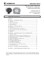
Table of Contents
SAFETY..................................................................................................2
SECTION 1 - INTRODUCTION.........................................................3
1-1. General.............................................................................................3
1-2. Main Components...........................................................................4
1-3. Indicating Switch..............................................................................5
1-4. Specifications....................................................................................6
SECTION 2 - INSTALLATION...........................................................7
2-1. General.............................................................................................7
2-2. Mounting/Piping/DPU Installation................................................7
2-3. Electrical Connection (Switches/Relays).......................................7
2-4. Switch Use........................................................................................7
2-5. Startup..............................................................................................7
SECTION 3 - MAINTENANCE AND CALIBRATION..................9
3-1. Required Tools.................................................................................9
3-2. DPU Installation/Test/Calibration/Maintenance..........................9
3-3. Bezel/Lens (or Cover) Installation and Removal.........................9
3-4. Calibration Check..........................................................................10
3-5. Pointer Installation and Removal.................................................10
3-6. Indicator Calibration.....................................................................11
3-7. Changing Switch Setpoint.............................................................12
3-8. Complete Calibration....................................................................14
3-9. Preventative Maintenance............................................................15
3-10. Locking Drive Arm to Torque Tube...........................................16
3-11. Troubleshooting...........................................................................16
SECTION 4 - INSTALLATION DRAWINGS..................................19
SECTION 5 - PARTS DRAWINGS/PARTS LISTS..........................23
[This manual is for the Indicating Switch only—refer to Model 199 DPU manual,
Part No. 10030, for detailed information about the DPU used with the indicating
switch.]
SAFETY
Before installing this instrument, review the installation instructions and safety
notices in Section 2 of this manual and in the Barton® Model 199 DPU manual.
DANGER notes indicate the presence of a hazard which will cause severe personal injury, death, or substantial property damage if warning is ignored.
WARNING notes indicate the presence of a hazard which can cause severe
personal injury, death, or substantial property damage if warning is ignore.
CAUTION notes indicate the presence of a hazard which will or can cause moderate personal injury or property damage if warning is ignored.
2
SECTION 1 - INTRODUCTION
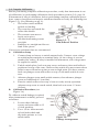
1-1. General
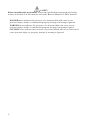
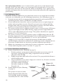
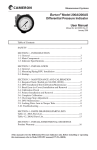
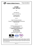
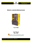
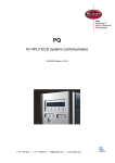
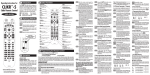
The Barton® weatherproof Model 289A and the explosion-proof Model 291B are
differential pressure indicating switches (Figure 1-1). The 289A has a NEMA-4
watertight die-cast aluminum case (finished with a weather-resistant black epoxy
resin paint). The cover lens is secured in the bezel with an elastomer ring to
reduce the possibility of accidental breakage. This ring also acts as a seal between
the bezel and the case to ensure a moisture, fume and dust-free atmosphere for
the indicator and switch mechanism.
Model 291B has an explosion-proof case that is certified for Class I, Division 1,
Groups B, C & D service. The large cover lens allows maximum readability of the
indicating pointer.
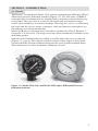
Switches and all adjustments are readily accessible when the cover is removed
(Figure 1-2, page 4). The built-in switches energize either single or dual alarm
circuits when the measured differential pressures exceed predetermined limits.
These limits may be either maximum, minimum, or both.
Figure 1-1. Model 289A (left) and Model 291B (right) Differential Pressure
Indicating Switches
3
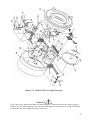
Figure 1-2. Switches and adjustable controls
1-2. Main Components
A. Indicating Switch
B. Differential Pressure Unit (DPU)
• 289A and 291B are actuated by a Barton® Model 199 DPU
For detailed information on the actuating DPU, see the Barton® Model 199 DPU
user manual (Part No. 10030).
4
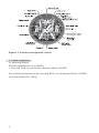
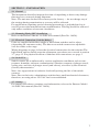
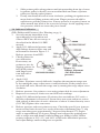
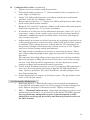
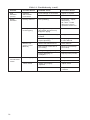
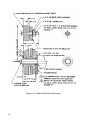
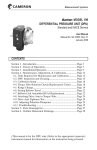
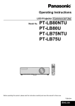
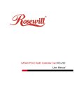
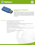
1-3. Indicating Switch (refer to Figures 1-3 and 2-1)
Rotation of the DPU’s torque tube shaft is coupled through connecting linkage
within the switch case to move the pointer across the scale plate. An actuating
cam, directly connected to the torque tube shaft, rotates with the motion of the
shaft. Two cam follower roller/actuator arm assemblies, one for each switch,
respond to torque tube rotation by opening and closing the switches as they ride
on and off the cam. The levels of differential pressure at which the switches actuate are adjustable with high and low alarm switch adjustments on the scale plate.
Standard models have two alarm switches - one or both may be used. Each switch
can be connected to operate normally-opened or normally-closed. The direct-set
switch contacts are adjustable over a scale range of 5-95% nominal.
Mid-point DP
BO T H S W I T C HES RELAX ED
50
C AM
HIGH
BLUE
❶
BLAC K
S W I T C H "B"
(RI GHT )
LOW
W HI T E
S W I T C H "A"
(LEFT )
Y ELLO W
RED
SWITCH
PLUNGER
S C REW
0
100
CLOSED
CONTACTS
SWITCH
OPEN
CONTACTS
A (LEFT)
YELLOW/BLUE
RED/YELLOW
B (RIGHT)
GREEN/WHITE
GREEN/BLACK
❶ Note: Wire "Green" for 289A
and "Violet" for 291B.
T ERM I NAL
BLO C K I N
C AS E
Zero DP
S W I T C H "A" AC T UAT ED/S W I T C H "B" RELAX ED
50
0
S W I T C H "A"
(LEFT )
S W I T C H "B"
(RI GHT )
100
CLOSED
CONTACTS
SWITCH
OPEN
CONTACTS
A (LEFT)
RED/YELLOW
YELLOW/BLUE
B (RIGHT)
GREEN/WHITE
GREEN/BLACK
Maximum DP
S W I T C H "A" RELAX ED/S W I T C H "B" AC T UAT ED
50
0
S W I T C H "A"
(LEFT )
S W I T C H "B"
(RI GHT )
100
SWITCH
CLOSED
CONTACTS
OPEN
CONTACTS
A (LEFT)
YELLOW/BLUE
RED/YELLOW
B (RIGHT)
GREEN/BLACK
GREEN/WHITE
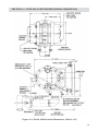
Figure 1-3. Switch Actuation Example
Notes: (1) Cam rotates counterclockwise with increased pressure; (2) Switches
shown with low switch set at 25% differential pressure (DP); High switch set at
75% differential pressure (DP); (3) To change setpoint: loosen lock screw, move
switch plate, tighten screw and test setpoint; (4) Internal wires use No. 22 AWG
and external wires use No. 18 AWG.
5
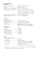
1-4. Specifications
General:
Actuating Unit (DPU)..................Barton® Model 199 DPU
Dial Size.........................................6 inches (152 mm)
Temperature Limits (Ambient)....40°F/°C to +180°F (+80°C)
Indication Accuracy (SPDT)........ 0-10” w.c. to 0-349” w.c. ± 1.0% F.S.
(0-25 mbar to 0-867 mbar ± 1.0% F.S.)
0-350” w.c. to 0-100 PSID ± 1.25% F.S.
(0-869 mbar to 0-6.9 bar ± 1.25% F.S.)
Indication Accuracy (DPDT).......Add 1% to SPDT values
Point of Switch Actuation.............Add 1/2% to SPDT values
Switch:
Accuracy of
Switch Repeatability.....................±0.25% of full scale
Switch Deadband..........................±5% (SPDT); ±6% (DPDT)
Switch Type....................................Mechanical, Snap-Acting
Contact Type..................................Single Pole, Double Throw (SPDT)
Double Pole, Double Throw (DPDT)
Switch Rating:
125 VAC.........................................5 Ampsa
250 VAC.........................................2.5 Ampsa
30 VDC Inductive.........................1.0 Ampsb
30 VDC Resistive..........................3.0 Amps
125 VDC Inductive.......................0.2 Ampsa,b
125 VDC Resistive........................0.4 Ampsa
Relay:
Coil Power Requirement:
DC Relay.................................1.5 Watts
AC Relay..................................2.75 Volt Amps
Contact Types................................Single Pole, Double Throw (SPDT)
Double Pole, Double Throw (DPDT)
Contact Rating..............................15 Amps at 115 VACa
CE Rating: Less than 50 VDC or 35 VAC
a
Non-CE Use Only. Voltage limited to less than 50 VDC or 35 VAC for CE applications.
b
Arc suppression recommended for inductive loadings.
6
SECTION 2 - INSTALLATION
2-1. General
The instrument should be inspected at time of unpacking to detect any damage
that may have occurred during shipment.
Note: The unit was checked for accuracy at the factory — do not change any of
the settings during examination or accuracy will be affected.
For applications requiring special cleaning/precautions, a polyethylene bag is
used to protect the instrument from contamination. This bag should be removed
only under conditions of extreme cleanliness.
2-2. Mounting/Piping/DPU Installation
Refer to the Barton® Model 199 DPU user manual (Part No. 10030).
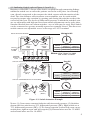
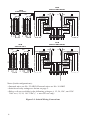
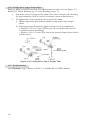
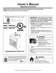
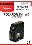
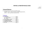
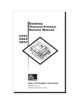
2-3. Electrical Connection (Switches/Relays)
Units are supplied with either single or dual alarm switches and/or relays
(depending on customer order). The direct-set switch contacts are adjustable
over the entire scale range.
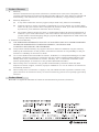
Wiring diagrams on page 8 show the electrical connections for the switches.The
high switch and low switch setpoint adjustment procedures are covered in section
3-7, page 12. For physical location of switches and connections, see page 3.
2-4. Switch Use
Switch contact life is influenced by various application conditions such as temperature, humidity, airborne contamination, vibration, amount of plunger travel,
cycling rate, and rate of plunger travel (and others), as well as by the electrical
(circuit) characteristics.
Note: Arc suppression for inductive loads will prolong the life of the switch
contacts.
Note: Due to their size, subminiature switches have small mechanical clearances;
therefore, no rating above 250 VAC has been established.
2-5. Startup
For startup procedures, warnings, and information, refer to the Barton® Model
199 DPU user manual (Part No. 10030).
7
289A
SWITCH AND RELAY
289A
SWITCH ONLY
HIGH
LOW
4
HIGH
4
N.C.
N.O.
C
WHITE/BLUE
WHITE/BROWN
N.C.
N.C.
WHITE/VIOLET
WHITE/BLACK
WHITE/ORANGE
N.C.
WHITE-VIOLET
WHITE-GREEN
WHITE-BLACK
C
N.O.
N.O.
N.C.
ORANGE
WHITE
VIOLET C
N.O.
N.C. BROWN
C BLUE
GRAY
N.O.
RED
BLACK
RED
BLACK
RED
YELLOW
BLUE
GRAY
BROWN
ORANGE
VIOLET
WHITE
GREEN
BLACK
N.C.
C
N.O.
WHITE
GREEN
BLACK
N.C.
C
N.O.
WHITE-RED
WHITE-YELLOW
WHITE-BLUE
N.O.
C
N.C.
RED
YELLOW
BLUE
C
N.O.
C
N.C.
4
N.O.
C
GREEN
WHITE/GRAY
YELLOW
4
LOW
291B
SWITCH AND RELAY
291B
SWITCH ONLY
LOW
4
4
HIGH
C
WHITE/BLUE
WHITE/BROWN
WHITE/VIOLET
WHITE/BLACK
WHITE/ORANGE
C
N.O.
N.O.
N.C. BROWN
C BLUE
GRAY
N.O.
RED
N.C.
ORANGE
WHITE
WHITE/RED C
BLACK N.O.
WHITE/BLACK/
BROWN
RED
YELLOW
BLUE
GRAY
BROWN
ORANGE
VIOLET
WHITE
BLACK/WHITE/BLACK
BLACK
GREEN
N.C.
C
N.O.
N.C.
C
WHITE-BLACK-BLUE
WHITE-BLACK-VIOLET
WHITE-BLACK-GRAY
WHITE
VIOLET
BLACK
4
N.O.
C
WHITE/YELLOW
N.C.
C
N.O.
WHITE-BLACK-RED
WHITE-BLACK-YELLOW
WHITE-BLACK-ORANGE
N.O.
C
N.C.
RED
YELLOW
BLUE
N.O.
C
N.C.
N.C.
VIOLET
WHITE/GRAY
N.C.
HIGH
N.C.
N.O.
GREEN
4
YELLOW
LOW
Notes (both configurations):
• Internal wires are No. 22 AWG; External wires are No. 18 AWG
• Switch and relay ratings are shown on page 5.
• Relay coils are available in the following voltages: 6, 12, 24, 120*, and 230*
VAC or 6, 12, 24, 110* VDC (* = non-CE use only)
Figure 2-1. Switch Wiring Connections
8
SECTION 3 - MAINTENANCE AND CALIBRATION
3-1. Required Tools (Toolkit Part No. 0288-1032B)
Tool
Purpose
Pointer puller Pointer removal
Small screwdriver Calibration adjustments
Medium screwdriver Bezel removal/DPU bracket screws
1/8” Open-end wrench Calibration adjustments
1/8 Hex Allen wrench Switch setpoint adjustment
3-2. DPU Installation/Test/Calibration/Maintenance
Refer to the Barton Model 199 DPU user manual (Part No. 10030).
3-3. Bezel/Lens (or Cover) Installation and Removal
WARNING
(EXPLOSIONPROOF UNITS)
PRIOR TO LOOSENING ANY ATTACHING HARDWARE, HOUSING BOLTS, OR
COVER ASSEMBLY, ASSURE SURROUNDING AREA IS, AND REMAINS, WELL
VENTILATED.
PRIOR TO LOOSENING OR REMOVAL CASE/COVER ASSEMBLY, ALL
ELECTRICAL POWER SUPPLIES MUST BE TURNED OFF.
THE COVER MUST BE REMOVED TO CALIBRATE THE INSTRUMENT.
BEFORE ANY MAINTENANCE/CALIBRATION, REVIEW MODEL 199 DPU
MANUAL (Part No. 10030).
For non-explosionproof units, the bezel gasket (Part No. 0277-0026C) must be
installed as shown below:
Figure 3-1.
Bezel/Lens
To remove the bezel and cover lens
on non-explosionproof units:
1. Loosen three screws on the
front of bezel.
2. Tilt out bottom of bezel and
slide bezel upward.
The two snubbers (Part No. 0266-0028C) on the scaleplate should not be compressed against the lens cover and the pointer should not touch the lens.
Note—Ensure correct bezel gasket orientation before placing instrument back in
service. Incorrect bezel gasket orientation will cause the instrument indicator to
jam, resulting in inaccurate readings.
9
For explosionproof units, cover is unscrewed to gain access to the internal components. Note: On some units, a set screw must be loosened with a 1/8-in. allen
wrench before the bezel can be removed. When re-installing cover, tighten cover
securely and inspect lens for cracks or other defects that may affect the explosionproof rating.
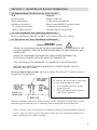
3-4. Calibration Check
Normally all that is required to put switch into service is to verify that it remains
at factory-set calibration, per the following instructions. (See Warning on pg. 9):
1. Securely mount unit in an appropriately level position and connect DPU to a
standard pressure source, per Model 199 DPU manual.
2. If zero indication is incorrect, remove bezel/lens (cover on explosionproof
units) and reset pointer to zero. Note: For an exact zero setting, hold the
hexagon hub with a wrench and carefully slip the pointer on its hub until it
points to zero graduation. Replace bezel/lens (or cover).
3. To test for reverse travel, connect pressure source to low-pressure (LP) housing and vent high-pressure (HP) housing. Apply pressures approximately
150% of the differential pressure range. The pointer should move approximately 5% to 10% below zero.
4. To test for overtravel, connect pressure source to HP housing and vent LP
housing. Apply pressures approximately 150% of differential pressure range.
Pointer should move approximately 5% to 10% above fullscale.
5. Apply 0%, 50% and 100% of full scale pressure. If indication is within
specified limits, instrument calibration is satisfactory and no adjustments are
necessary. If indications are incorrect, perform calibration procedure.
6. Make sure instrument zero indication is correct; otherwise, repeat Step 2.
7. Verify switch setpoints (refer to section 3-7, page 12).
3-5. Pointer Installation and Removal
A. Pointer Installation (See Warning on page 9)
1. Position pointer on movement shaft with pointer set at zero scale. If
necessary, enlarge hub hole using a tapered broach (in toolkit)
(Part No. 0288-1032B).
2. Lightly tap pointer hub with a flat-end tool. Use perpendicular blows to
avoid bending shaft.
3. Check calibration over entire range (see section 3-8.). If unit is correctly
calibrated, secure pointer to
movement shaft by tapping
Figure 3-2.
hub with a hand-set or other
Pointer Puller
flat-end tool.
B. Pointer Removal (See Warning
on page 9)
The pointer is removed with
Barton Pointer Puller (Part No.
0163-0005B), which is included
in toolkit (Part No. 0288-1032B).
10
1.
2.
Slide pointer puller along pointer until pin protruding from tip of screw
in pointer puller is directly over movement shaft and arms of pointer
puller are directly under pointer.
Gently turn knurled head of screw clockwise, pushing pin against movement shaft and lifting pointer with arms. Finger pressure should be
sufficient to pull the pointer free. If more pressure is required, insert an
Allen wrench into head of the screw for leverage. Avoid applying excessive pressure, which can cause the pin to break.
3-6. Indicator Calibration
(DP=Differential Pressure) (See Warning on pg. 9)
1. Securely mount instrument in an
approximately level position and
connect DPU into the test setup, as
described in the Model 199 DPU
manual.
2. Apply 50% differential pressure and
align linkage between drive arm and
movement as shown in Figure 3-3.
Release pressure from DPU.
3. Check pointer for
zero indication.
If necessary, set
pointer to zero by
slipping pointer on
Figure 3-3.
hub (hold pointer
Linkage Alignment
with fingers and
(50% differential
turn hub with a
pressure)
wrench).
4. Apply 100%
pressure. If pointer exceeds full-scale, lengthen the movement range arm
by by turning the range adjust screw counterclockwise. If the pointer does
not reach full scale, shorten the range arm by turning the range adjust screw
clockwise.
5. Release pressure. Set pointer to zero using pointer hub for zero adjustment.
6. Repeat as necessary to obtain zero and full-scale readings.
7. Apply 50% differential pressure. If pointer does not indicate 50% scale, a
linearity adjustment is necessary. Loosen drive arm screw and move arm to
shift pointer in direction of error a distance of about 10 times linearity error.
(50% DP) Tighten drive arm screw.
8. Release pressure and reset pointer at zero. Check the span. If gear in movement reaches limit of travel as a result of linearity adjustment (step 7), slip
range arm along gear approximately 5 degrees from normal 37.5 degree
angle to approximately 43 degrees. Range arm is slipped by applying pressure to range arm with thumb, while holding gear firmly in place. Retest
pointer response at 50%, 0%, and 100% of full-scale differential pressure,
and adjust linkage until readings are acceptable.
11
9.
Apply 0%, 25%, 50%, 75%, 100%, 75%, 50%, 25%, and 0% of full-scale
differential pressure consecutively to instrument without overshoot. Lightly
tap indicator to overcome friction. Pointer should accurately indicate each
applied pressure.
10. Set stops to prevent pointer from striking snubbers on scale. Test setting by
moving pointer from zero position to 50% position manually and then letting
pointer return freely. If necessary, tap pointer hub to tighten it to shaft.
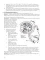
3-7. Changing Switch Setpoint
(Tools: Screwdriver, 1/8 Hex Allen wrench) (See Warning on pg. 9)
Setpoint — The measured pressure at which the snap-switch actuates and thereby
changes the states of the N.O and N.C. contacts. For example, the setpoint of the
low switch is 24 psid with decreasing pressure.
Deadband — The difference in the measured pressures between switch-actuation
and switch-reset. Deadband is
usually expressed as percentage of full scale (% of F.S.).
Deadband is not adjustable.
For example, the switch above
was found to reset at 26.4 psid
with increasing pressure. The
deadband was 2.4 psi, or 4% of
the full scale (0 to 60 psid).
A. In-Service Instruments
(calibration pressures
cannot be applied)
1. Remove bezel. Do
not remove pointer or
scale.
Figure 3-4.
2. Insert hex wrench in
Setpoint
switch adjust post,
Adjustment
(item A, Fig. 3-4).
3. Loosen switch lockscrew, (item B), 1/2 to
1 turn.
4. With hex wrench,
move index pointer
(item C) to new setpoint as indicated on switch index (item D).
5. If possible, check setpoint by varying process pressures and observing
pointer readings when switch actuates. (Open manifold bypass valve
slowly and watch for “pointer-jump” at setpoint or by electrical signal.)
Adjust setting if necessary, repeat test several times to verify stability.
Note: Switch index has 10 divisions shown by tick marks in Figure 3-4. Positions 0,
5, and 10 are also labeled along the bottom of the index as well.
Example: Scale has range of 0-60 psid. Setpoint is 24 psid, with decreasing pressure, (24/60 x 10 = 4).
12
Move index pointer (item C) to division 4. Start from bottom of switch index (0
on low, 10 on high). Tighten switch lock (item B) snug plus 1/4 turn. Do not overtighten. This will place setpoint within ±2% of full scale.
B. Out-of-Service (Disconnected from process Setpoint Adjustment lines or
mounted on bench)
1. Drain and vent housings.
2. Attach calibration pressure source (air or N2) to HP housing.
3. Apply pressures and observe pointer readings for accuracy. Use a
pressure standard (Heise gage or equivalent) for reference. Change
pressures slowly in discrete steps. A “bleed-pressure” method may cause
errors.
4. Change switch setpoint as described in Part A, page 12.
5. Check setpoint by changing measured pressure to actuate switch. For
Example: To verify low-switch setpoint to 24 psid, apply approximately
30 psi. Then reduce pressure to approximately 25 psid, hold for a few
seconds, then continue in 1/4 psid steps until switch actuates. If setpoint
is incorrect, continue instructions in Part A.
6. To measure switch deadband, reduce pressure to zero, then increase
pressure until switch resets.
7. To verify repeatability of setpoint, repeat step 5 several times. For
improved accuracy, use smaller increments of pressure. Allow extra
time for slow response gages and for test systems that have long runs of
small bore tubing.
8. High alarm switches right side of the scale) are adjusted in a similar
manner. Apply increasing pressure to establish the switch setpoint,
decreasing pressure to measure deadband.
C. Notes
1. Always check setpoint after tightening switch lock screws.
2. Either switch may be set at any point of the scale, except allowance must
be made for deadband to enable switch to reset itself. For example, high
switch (right side of scale) may be set at 100% of F.S., but should not be
set near zero. Also, low switch may be set at zero, but not near full scale.
(Observe deadband values for specific models).
3. If switch performance is unsatisfactory (such as setpoint does not
repeat, deadband is excessive, pointer exhibits hysteresis, contacts are
unstable. etc.) remove scale and inspect switch and mechanism. Scale is
split for removal without pulling pointer.
a. SPDT: This is the standard model (low, high, or both).
b. DPDT: Two switches are stacked and actuated by a single lever (low,
high, or both).
c. Three (or four) SPDT: Switches have independent switch points.
Nos. 1 and 3 are usually low switches set for decreasing pressures.
Nos. 2 and 4 are usually set for increasing pressures.
d. Hermetically Sealed Switch (Micro 11HM41): this switch has wide
deadband, case is modified for electrical clearances, amperes are
reduced for 60 Hz service.
13
3-8. Complete Calibration
Before performing complete calibration procedure, verify that instrument is out
of calibration, by performing calibration check procedure (section 3-4), page 10.
If instrument is out of calibration, before performing complete calibration procedure, remove bezel/lens and inspect switch mechanism to verify the following (see
Figure 3-5) (See Warning on pg. 9):
• The roller rotates without
wobble or binding.
• The cam does not touch the
roller side shields.
• The actuator arm moves
freely on its pivot.
• All switch mounting screws
Figure 3-5.
are tight.
Cam/Follower Position
• Linkages are straight and do not
bind at the pivots.
Correct any problems that are encountered.
A. Calibration Setup
1. Connect lamp or buzzer to switch output leads. Connect a test voltage
to switch input terminals on terminal strip. (A low voltage is recommended for safety.) If relay is installed in instrument, coil voltage must
be applied to switch.
2. Unlock switch plate, back out stop screw, and move plate until roller is
positioned at top of the cam. Observe that switch does not actuate when
roller is moved from low point on cam to high point. If it does actuate,
back out plunger screw with roller on top of cam until switch de-actuates.
3. Advance plunger screw until switch actuates, then advance plunger
screw an additional 60° (one flat).
4. Exercise switch roller across top of cam to verify steady operation.
Advance stop screw to touch switch, then back out screw 1.5 turns
(9 flats).
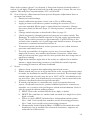
B. Calibration Procedure (see
Figure 3-6)
To calibrate switch linkage (required
when instrument is rebuilt), proceed
as follows:
1. Loosen three linkage
screws and turn crank to 12
o’clock position.
2. Use a 1/8-in. Allen wrench
to hold index shaft and
slip index pointer to 0 on
switch index.
Figure 3-6.
Linkage Arrangement
14
B. Calibration Procedure (continued)
3. Tighten screw on crank to mid-slot position.
4. Turn switch index pointer to “1” (index numbers refer to numbers on
outer edge of scaleplate).
5. Apply 10% differential pressure and adjust switch plate until switch
actuates. Lock the two linkage screws.
6. Rotate index pointer to “9.” Apply 90% differential pressure and adjust
crank radius until switch actuates.
7. Recheck 10% and 90% setpoints. Adjust crank radius and index pointer
until both setpoints are 2% accurate (nominal).
8. If switch is to be field-set at low differential pressure values (1% or 2%
of pressure range), check crank to prevent a top-dead-center position.
Otherwise, minimum setpoint position will be restricted and setpoint
may become reversed.
9. Adjust switch to actuate at desired pressure by applying test pressures in
a decreasing direction, in discrete steps. Allow unit and pressure system
to stabilize. Then change pressure a small amount. The magnitude of
the pressure change is determined by desired accuracy of test. Tighten
lock screw before testing switch performance.
The high switch is usually set to actuate at increasing pressure. Therefore, when calibrating high switch, apply test pressure in an increasing
direction.
This amount of loading will prevent cam-runout of a similar condition.
Excessive plunger loading (more than 3 flats) may cause roller to drag
on cam. Cam friction will be apparent by excessive hysteresis, erratic
pointer readings and inconsistent switch operation.
10. Check switch deadband, (actuate to reset) by applying differential pressures in a decreasing then increasing (opposite for high switch direction). Observe pressures. To reduce deadband, advance plunger screw
(two flats maximum).
11. Adjust high switch to actuate at desired pressure. The procedure is the
same as for the low switch.
3-9. Preventative Maintenance
• Indicating Switch — Periodically inspect alarm switch mechanism to
verify that all mounting screws are seated properly. Inspect linkage for
wear. Inspect integrity of electrical circuits. Tighten as necessary.
• DPU — Warning/Caution notices, inspection/cleaning procedures, and
maintenance procedures are presented in the Model 199 DPU manual.
Never perform any maintenance/repair on the instrument or DPU
without first reviewing all procedures and Warning/Caution notices in
the DPU manual.
15
3-10. Locking Drive Arm to Torque Tube
Refer to Model 199 DPU manual. For explosionproof units, refer to Figure 5-3,
Model 291 Detail Drawing, pg. 28 (See Warning on pg. 9).
1. Slip drive arm over torque tube shaft; clear end of torque-tube housing
by approximately 0.030-in. before securing to prevent interference.
2. To tighten drive arm assembly onto torque-tube shaft:
a. While supporting block/shaft, tighten clamp screw until snug to
shaft.
b. S
till supporting block/shaft, tighten clamp screw an additional:
• Sintered: 1/3 to 1/2 turn (This screw can normally turn one full
revolution before breaking.)
• Slotted: 1/4 to 1/3 turn (The slot in the slotted clamp block should
still be open.)
Figure 3-4. Locking Drive Arm to Torque Tube
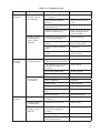
3-11. Troubleshooting
(See Warning on pg. 9. Refer to Table 3-1 and Model 199 DPU manual.
16
Table 3-1. Troubleshooting
Problem
Possible Source
Probable Cause
Corrective Action
Low or no
Indication
Primary element
or DPU (refer to
DPU Manual)
Orifice installed backwards
or oversized
Replace orifice.
Flow blocked upstream
from run
Clean out run or open
valve.
Loss of liquid in reference
leg (liquid level)
Refill reference leg.
Density changes in process
media or reference leg
Refill reference leg with
same density liquid as
process media.
Pressure tap holes plugged
and/or piping plugged
Clean out piping.
Bypass valve open or
leaking
Close bypass valve(s)
and/or repair leaks.
Liquids or gases trapped in
piping
Vent piping.
Block or shutoff valves
closed
Open block or
shutoff valves.
Piping leaks on HP side
Repair leaks.
Housing filled with solids
restricting bellows movement
Clean out housing.
Gas (liquid service) or liquid
(gas service) trapped in
housing
Vent housing.
HP housng gasket leak
Replace gasket.
DPU tampered with
Return BUA for repair.
Loose linkage or movement
Tighten or replace.
Out of calibration
Calibrate.
Pointer loose
Tighten pointer.
Dirty or corroded mechanism
Clean or replace.
Wiring interfering with movement
Re-route wiring.
Dirty mechanism
Clean mechanism.
Primary source
Orifice partially restricted or
too small
Clean out or replace.
Primary element
to DPU piping
Piping leaks on LP side
Repair leaks.
Bellows unit
(Refer to DPU
Manual)
Gas (liquid service) or liquid
(gas service) trapped in
housing
Vent housing.
LP housing gasket leak
Replace gasket.
Range Spring broken or
DPU tampered with
Return BUA for repair.
Primary element
to DPU piping
(refer to DPU
Manual)
Low or no
Indication
(cont'd)
Bellows unit (refer
to DPU Manual)
Indicator,
alarm switch
mechanism
High
indication
17
Table 3-1. Troubleshooting (cont'd)
Problem
Possible Source
Probable Cause
Corrective Action
High
indication
(cont'd)
Indicator,
alarm switch
mechanism
Loose linkage or movement
Tighten or replace.
Out of Calibration
Calibrate.
Erratic
indication
Primary element
Flow pulsating
M199 DPU – adjust
dampening;
All o hers – install
dampening device
upstream of DPU run.
Primary element
to DPU piping
Liquid (gas service) or
gas bubble (liquid service)
trapped in piping
Remove.
Vapor generator incorrectly
installed
Re-pipe.
Reference leg gassy or
Liquid vaporizing
See piping instruc ions
in DPU Manual.
Obstructed bellows travel
Clean bellows.
Gas trapped in DPU HP or
LP housing
Remove (see Startup
procedure).
Linkage dragging or dirty
Adjust or clean.
Pointer dragging on
scaleplate
Adjust pointer posi ion.
Blown fuse
Replace fuse.
Broken or loose wire
Repair.
Switch not properly
adjusted
Adjust switch.
Dirty or burned
Replace switch
contacts.
Bellows unit
(Refer to DPU
Manual)
Inaccurate or
No Electrical
Alarm
Power supply
Alarm switch
18
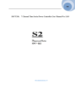
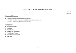
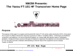
SECTION 4 - INSTALLATION/DIMENSIONAL DRAWINGS
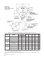
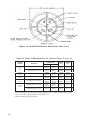
Figure 4-1. Model 289A Outside Dimensions (Part 1 of 2)
19
Figure 4-2.
Model 289A
Outside Dimensions
(Part 2 of 2)
PRESSURE
RATING
PSI (MPa)
TOP
BOTTOM
DIM. A
INCHES
(mm)
DIM. B
INCHES
(mm)
DIM. C
INCHES
(mm)
DIM. D
INCHES
(mm)
# BOLTS
Table 4-1. Model 289A Dimensions (as shown in Figure 4-1, pg. 19)
CAST ALUM. 356-T6
1/2 NPT
(Note 1)
1/4 NPT
(Note 1)
9-29/32
(251.6)
6-5/8
(168.3)
2
(50.8)
2-9/64
(51.2)
6
FORGED STNL. ST. 316
1/2 NPT
(Note 1)
1/4 NPT
(Note 1)
9-29/32
(251.6)
6-5/8
(168.3)
2
(50.8)
2-9/64
(51.2)
12
FORGED ST. AISI C1018
1/2 NPT
(Note 1)
1/4 NPT
(Note 1)
10-5/32
(257.9)
7-1/8
(181.0)
2|
(50.8)
2-9/64
(51.2)
6
FORGED STNL. ST. 316
1/2 NPT
(Note 1)
1/4 NPT
(Note 1)
10-5/32
(257.9)
7-1/8
(181.0)
2
(50.8)
2-9/64
(51.2)
12
MONEL K500
1/2 NPT
(Note 1)
1/4 NPT
(Note 1)
10-5/32
(257.9)
7-1/8
(181.0)
2
(50.8)
2-9/64
(51.2)
12
FORGED ALLOY ST 4142
1/2 NPT
(Note 1)
1/4 NPT
(Note 1)
10-5/32
(257.9)
7-1/8
(181.0)
2
(50.8)
2-9/64
(51.2)
12
9/16-18
UNF
(Note 2)
9/16-18
UNF
(Note 2)
10-5/32
7-1/8
(257.9)
(181.0)
2
(50.8)
2
(50.8)
12
1/2 NPT
(Note 1)
1/4 NPT
(Note 1)
10-5/32
7-1/8
(257.9)
(181.0)
2
(50.8)
2-9/64
(51.2)
12
HOUSING
MATERIAL
1,000
(6.9)
2,500
(17.2)
3,000
(20.7)
4,500
(31.0)
FORGED ALLOY ST 4142
6,000
(41.4)
FORGED STNL ST 17-4 PH
FORGED ALLOY ST 4142
FORGED STNL ST 17-4 PH
PRESSURE
CONNECTION
Note 1: Can be reversed when ordered or can be rotated 180° in the field.
Note 2: Suitable for use with Aminko fittings (American Inst. Co., Silver Springs, MD) or equiv.
Note 3: AlI standard pipe fittings furnished by customer.
Note 4: Cast alum. pipe mount supplied, unless otherwise specified. Specify pipe size when ordering threaded Stl.
adapter.
Metric conversions are approximate.
20
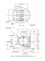
Figure 4-3. Model 291B Outside Dimensions (Part 1 of 2)
21
Figure 4-4. Model 291B Outside Dimensions (Part 2 of 2)
PRESSURE
RATING
PSI (MPa)
3,000
(20.7)
4,500
(31.0)
TOP
BOTTOM
CAST ALUM. 356-T6
1/2 NPT
(Note 1)
1/4 NPT
(Note 1)
12
(304.8)
6-5/8
(168.3)
6
FORGED STNL. ST. 316
1/2 NPT
(Note 1)
1/4 NPT
(Note 1)
12
(304.8)
6-5/8
(168.3)
12
FORGED ST. AISI C1018
1/2 NPT
(Note 1)
1/4 NPT
(Note 1)
12-1/4
(309.9)
7-1/8
(181.0)
6
FORGED STNL. ST. 316
1/2 NPT
(Note 1)
1/4 NPT
(Note 1)
12-1/4
(309.9)
7-1/8
(181.0)
12
FORGED ALLOY ST 4142
1/2 NPT
(Note 1)
1/4 NPT
(Note 1)
12-1/4
(309.9)
7-1/8
(181.0)
12
9/16-18
UNF
(Note 2)
9/16-18
UNF
(Note 2)
12-1/4
(309.9)
(181.0)
1/2 NPT
(Note 1)
1/4 NPT
(Note 1)
12-1/4
(309.9)
(181.0)
FORGED ALLOY ST 4142
6,000
(41.4)
DIM. B
INCHES
(mm)
DIM. A
INCHES
(mm)
HOUSING
MATERIAL
1,000
(6.9)
2,500
(17.2)
PRESSURE
CONNECTION
# BOLTS
Table 4-2. Model 291B Dimensions (as shown in Figure 4-3, pg. 21)
FORGED STNL ST 17-4 PH
FORGED ALLOY ST 4142
FORGED STNL ST 17-4 PH
7-1/8
7-1/8
12
12
Note 1: Can be reversed when ordered or can be rotated 180° in the field.
Note 2: Suitable for use with Aminko fittings (American Inst. Co., Silver Springs, MD) or equiv.
Note 3: For Aminco ports, dimension is 2 in. (50 8 mm).
Metric conversions are approximate.
22
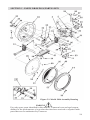
SECTION 5 - PARTS DRAWINGS/PARTS LISTS
Figure 5-1. Model 289A Assembly Drawing
WARNING
Use only spare parts identified in this manual. Cameron bears no legal responsibility for the performance of a product that has been serviced or repaired with
parts that are not authorized by Cameron.
23
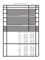
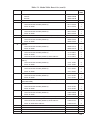
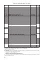
Table 5-1. Model 289A Parts List
ITEM
1
2
3
4
5
DESCRIPTION
DIFFERENTIAL PRESSURE UNIT (NOT SHOWN)
PART NO.
PER
UNIT
SEE DPU 199
MANUAL
1
LOW ALARM, EXT. WIRING ASSY., 2.5’ LENGTH (NOT SHOWN):
UNITS WITHOUT RELAY, SPDT
0288-0021B
UNITS WITHOUT RELAY, DPDT
S401-0018Z
UNITS WITH RELAY, SPDT OR DPDT
0288-0008B
HIGH ALARM, EXT. WIRING ASSY., 2.5’ LENGTH (NOT SHOWN):
UNITS WITHOUT RELAY. SPDT
S655-0056B
UNITS WITHOUT RELAY, DPDT
S401-0093Z
UNITS WITH RELAY, SPDT OR DPDT
0288-0007B
LOW ALARM, SWITCH ASSY.:
0288-0024B
UNITS WITHOUT RELAY, DPDT
S401-0053Z
UNITS WITH RELAY, SPDT OR DPDT
0288-0039B
HIGH ALARM, SWITCH ASSY.:
1
UNITS WITHOUT RELAY, SPDT
0288-0025B
UNITS WITHOUT RELAY, DPDT
S401-0056Z
UNITS WITH RELAY, SPDT OR DPDT
0288-0040B
NOT USED
1
1
UNITS WITHOUT RELAY. SPDT
6
1
7
LOW ALARM DRIVE PLATE ASSY.
0288-0026B
1
8
HIGH ALARM DRIVE PLATE ASSY.
0288-0027B
1
9
LOW SWITCH ADJUSTMENT INDEX ASSY.
0288-0028B
1
10
HIGH SWITCH ADJUSTMENT INDEX ASSY.
0288-0029B
1
11
LOW RELAY ASSY. ( * = Non-CE Use Only):
Coil Voltage
12
24
1
Wired SPDT
Wired DPDT
6 VAC
0288-0015B
0288-1045B
12 VAC
0288-0045B
0288-1035B
24 VAC
0288-0016B
0288-1044B
*125 VAC
0288-0017B
0288-1043B
*250 VAC
0288-0046B
0288-1034B
6 VDC
0288-0018B
0288-1038B
12 VDC
0288-0019B
0288-1037B
24 VDC
0288-0020B
0288-1036B
*110 VDC
0288-0047B
0288-1033B
Coil Voltage
Wired SPDT
Wired DPDT
HIGH RELAY ASSY. ( * = Non-CE Use Only):
1
6VAC
0288-0009B
0288-1054B
12 VAC
0288-0042B
0288-1048B
24 VAC
0288-0010B
0288-1053B
*125 VAC
0288-0011B
0288-1052B
*250 VAC
0288-0043B
0288-1047B
6VDC
0288-0012B
0288-1051B
12 VDC
0288-0013B
0288-1050B
24 VDC
0288-0014B
0288-1049B
*110 VDC
0288-0044B
0288-1046B
Table 5-1. Model 289A Parts List (cont'd)
ITEM
DESCRIPTION
**13
POINTER ASSY.:
0288-0030B
BLACK
0288-0031B
BEZEL ASSY. (WITH PLASTIC LENS)
15
PLATE SCREW:
0277-0018B
1
LOW OR HIGH ALARM (SINGLE)
0317-0012C
1
DUAL ALARM
0317-0012C
2
LOW OR HIGH ALARM (SINGLE)
0257-0019C
1
DUAL ALARM
0257-0019C
2
0258-0007C
1
LOW OR HIGH ALARM (SINGLE)
0288-0016C
1
DUAL ALARM
0288-0016C
2
LOW OR HIGH ALARM (SINGLE)
0288-0017C
1
DUAL ALARM
0288-0017C
2
LOW OR HIGH ALARM (SINGLE)
0111-0007J
5
DUAL ALARM
0111-0007J
4
LOW OR HIGH ALARM (SINGLE) WITH RELAY
0111-0007J
3
LOW OR HIGH ALARM (SINGLE)
0112-1022J
2
DUAL ALARM
0112-1022J
4
LOW OR HIGH ALARM (SINGLE)
0117-0007J
3
DUAL ALARM
0117-0007J
6
LOW OR HIGH ALARM (SINGLE)
0117-0016J
1
DUAL ALARM
0117-0016J
2
0119-0042J
1
LOW OR HIGH ALARM (SINGLE)
0317-0019J
1
DUAL ALARM
0317-0019J
2
SPRING WASHER:
17
SWITCH PLATE SPACER, HIGH ALARM (SINGLE)
18
LINK PLATE:
19
20
21
22
23
24
PER
UNIT
1
WHITE
14
16
PART NO.
STRAP:
PLUG, SCREW, 4-40 X 1/8. SL., RD., HD. (NOT SHOWN):
SCREW, 4-40 X 1/4 SST SL. ,FL., HD. (WITH RELAY
ONLY):
SCREW, 3-48 X 3/16, SST SL., BINDING HD.:
SCREW, 8-32 X 1/4, SST, SL., BINDING HD.:
PLUG SCR., 8-32 X 1/4, SST, PAN HD. (SINGLE)
(NOT SHOWN)
25
26
WASHER, SST:
WASHER, NO.3 FLAT, SST:
LOW OR HIGH ALARM (SINGLE)
0003-0045K
4
DUAL ALARM
0003-0045K
8
0087-0011 T
1
LOW OR HIGH ALARM (SINGLE) WITH RELAY
0109-0017T
1
DUAL ALARM WITH RELAY
0109-0017T
2
27
GRIP RING (LOW/HIGH ALM.) (SINGLE/DUAL)
28
WIRE NUT CONNECTOR (NOT SHOWN):
29
MOVEMENT ASSEMBLY
0288-0035B
1
30
LINK ASSEMBLY
0288-0036B
1
31
DRIVE ARM ASSEMBLY: 289A (199 DPU)
0288-0037B
1
32
CASE ASSEMBLY
0288-0038B
1
25
Table 5-1. Model 289A Parts List (cont'd)
ITEM
DESCRIPTION
PART NO.
PER
UNIT
32
CASE ASSEMBLY
0288-0038B
1
33
SCREW, RETAINER
0181-0007C
3
34
STOP, SNUBBER
0226-0028C
2
**35
GASKET, BEZEL
0277-0026C
1
36
RISER, MOVEMENT
0277-0035C
2
37
BRACKET, STOP
0288-0028C
1
38
BRACKET, TERMINAL BLOCK
0288-0029C
1
39
SCREW, 6-32 X 3/8, SL., RD., HD.
0111-0015J
2
40
SCREW, 4-40 X 3/16 SST, SL., FIL., HD.
0114-0023J
4
41
SCREW, 4-40 X 3/16, SST., SL, BINDING HD.
0117-0012J
1
42
SCREW, 6-32 X 3/16 SST, SL. BINDING HD.
0117-0013J
4
43
SCREW, 10-32 X 1/2, FL. HD., SOC.
0240-0015J
10
44
SCREW, 1/2-20 X 1, SL. SET SCREW
0340-0003J
4
45
NUT, 1/4-20 HEX
0500-0010J
4
46
STUD, BEZEL, RETAINING, DRIV-LOK
0004-0005K
1
47
BLOCK, TERMINAL
0038-0033T
1
48
PLATE, SCALE (SEE NOTES BELOW):
0288-0031C
WHITE
0288-1014C
49
ID. TAG (NOT SHOWN)
50
SWITCH, WIRED, LOW ALARM (NOT SHOWN):
LOW ALARM, SPDT (WITHOUT RELAY)
51
1
BLACK
0199-0125C
1
0257-0009B
LOW ALARM, DPDT (WITHOUT RELAY) #1
0257-0009B
LOW ALARM, DPDT (WITHOUT RELAY) #2
S401-0016Z
LOW ALARM (WITH RELAY)
0288-0004B
SWITCH, WIRED, HIGH ALARM (NOT SHOWN):
HIGH ALARM, SPDT (WITHOUT RELAY)
1
1
0257-0008B
HIGH ALARM, DPDT (WITHOUT RELAY) #1
0257-0008B
HIGH ALARM, DPDT (WITHOUT RELAY) #2
S401-0017Z
HIGH ALARM (WITH RELAY)
0288-0003B
52
DISC, SEALER, 112” (WITH 3M 468 ADHESIVE)
0192-1035T
1
53
CALIBRATION KIT (NOT SHOWN)
0288-1032B
1
1
54
INSULATOR STRIP
0038-1345T
55
LENS (PLASTIC)
0181-0038C
1
56
PULLER, POINTER (NOT SHOWN)
0163-0005B
1
57
RETAINER RING:
SINGLE ALARM
0087-0015T
1
DUAL ALARM
0087-0015T
2
* INDICATES NON-CE USE ONLY.
** INDICATES RECOMMENDED SPARE PART. WHEN ORDERING PARTS, PLEASE SPECIFY THE SERIAL
NUMBER OF THE INSTRUMENT WITH WHICH THEY ARE TO BE USED.
SCALEPLATE IDENTIFICATION:
IF THE PLATE SHOWS AN SCR NUMBER, THIS WITH IDENTIFY IT. OTHERWISE, PROVIDE THE FOLLOWINGINFORMATION:
• SQUARE ROOT OR LINEAR GRADUCATION
• SCALE (E.G., 0-100, 25-0-100, ETC.)
• NUMBER OF GRADUATIONS (LINEAR SCALES ONLY)
• DATA (E.G., PSID, INCHES WATER COLUMN, ETC.)
IF THE PLATE HAS MULTIPLE SCALES OR COLORS (OTHER THAN BLACK AND WHITE), CONSULT FACTORY
FOR PRICING/DESCRIPTION.
26
Figure 5-2. Model 291B Assembly Drawing
WARNING
Use only spare parts identified in this manual. Cameron bears no legal responsibility for the performance of a product that has been serviced or repaired with
parts that are not authorized by Cameron.
27
Figure 5-3. Model 291B Detail Drawing
28
Table 5-2. Model 291B Parts List
ITEM
DESCRIPTION
1
DIFFERENTIAL PRESSURE UNIT (NOT SHOWN)
2
HIGH EXTERNAL WIRING ASSY. (2.5’ Long):
3
4
5
PART NO.
PER
UNIT
SEE DPU 199
MANUAL
1
1
HIGH ALARM, SPDT (WITHOUT RELAY)
S655-0056B
HIGH ALARM, DPDT (WITHOUT RELAY)
290B-1090B
HIGH ALARM (WITH RELAY)
290B-1084B
1
LOW EXTERNAL WIRING ASSY. (2.5’ Long):
LOW ALARM, SPDT (WITHOUT RELAY)
0288-0021B
LOW ALARM, DPDT (WITHOUT RELAY)
290B-1089B
LOW ALARM (WITH RELAY)
0288-0008B
1
LOW SWITCH ASSY.:
LOW ALARM, SPDT (WITHOUT RELAY)
0288-0024B
LOW ALARM, DPDT (WITHOUT RELAY)
290B-1010B
LOW ALARM (WITH RELAY)
0288-0039B
1
HIGH SWITCH ASSY.:
HIGH ALARM, SPDT (WITHOUT RELAY)
290B-1006B
HIGH ALARM, DPDT (WITHOUT RELAY)
290B-1012B
HIGH ALARM (WITH RELAY)
290B-1008B
6
LOW ALARM DRIVE PLATE ASSY.
0288-0026B
1
7
HIGH ALARM DRIVE PLATE ASSY.
0288-0027B
1
8
LOW SWITCH ADJUSTMENT INDEX ASSY.
0288-0028B
1
9
HIGH SWITCH ADJUSTMENT INDEX ASSY.
0288-0029B
1
10
LOW RELAY ASSY. ( * = Non-CE Use Only):
11
1
Coil Voltage
Wired SPDT
Wired DPDT
6 VAC
0288-0015B
0288-1045B
12 VAC
0288-0045B
0288-1035B
24 VAC
0288-0016B
0288-1044B
*125 VAC
0288-0017B
0288-1043B
*250 VAC
0288-0046B
0288-1034B
6 VDC
0288-0018B
0288-1038B
12 VDC
0288-0019B
0288-1037B
24 VDC
0288-0020B
0288-1036B
*110 VDC
0288-0047B
0288-1033B
HIGH RELAY ASSY. ( * = Non-CE Use Only):
1
Coil Voltage
Wired SPDT
Wired DPDT
6VAC
0288-0009B
0288-1054B
12 VAC
0288-0042B
0288-1048B
24 VAC
0288-0010B
0288-1053B
*125 VAC
0288-0011B
0288-1052B
*250 VAC
0288-0043B
0288-1047B
6VDC
0288-0012B
0288-1051B
12 VDC
0288-0013B
0288-1050B
24 VDC
0288-0014B
0288-1049B
*110 VDC
0288-0044B
0288-1046B
29
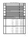
Table 5-2. Model 291B Parts List (cont'd)
ITEM
**12
13
PART NO.
PER
UNIT
1
POINTER ASSY.:
WHITE
0288-0030B
BLACK
0288-0031B
PLATE SCREW:
LOW OR HIGH ALARM (SINGLE)
0317-0012C
1
DUAL ALARM
0317-0012C
2
LOW OR HIGH ALARM (SINGLE)
0257-0019C
1
DUAL ALARM
0257-0019C
2
0258-0007C
1
LOW OR HIGH ALARM (SINGLE)
0288-0016C
1
DUAL ALARM
0288-0016C
2
LOW OR HIGH ALARM (SINGLE)
0288-0017C
1
DUAL ALARM
0288-0017C
2
LOW OR HIGH ALARM (SINGLE)
0117-0007J
3
DUAL ALARM
0117-0007J
6
LOW OR HIGH ALARM (SINGLE)
0112-0037J
2
DUAL ALARM
0112-0037J
4
LOW OR HIGH ALARM (SINGLE)
0117-0016J
1
DUAL ALARM
0117-0016J
2
LOW OR HIGH ALARM (SINGLE)
0317-0019J
1
DUAL ALARM
0317-0019J
2
LOW OR HIGH ALARM (SINGLE)
0003-0045K
4
DUAL ALARM
0003-0045K
8
0087 -0011 T
1
LOW OR HIGH ALARM (SINGLE) WITH RELAY
0109-0017T
1
DUAL ALARM WITH RELAY
0109-0017T
2
MOVEMENT ASSEMBLY
0288-0035B
1
26
LINK ASSEMBLY
0288-0036B
1
27
DRIVE ARM ASSEMBLY: 289A (199 DPU)
0288-0037B
1
28
PLATE, MOUNTING ASSEMBLY
0290-0002B
1
29
STOP, SNUBBER
0226-0028C
2
30
RISER, MOVEMENT
0277-0035C
2
31
RISER, SCALEPLATE
0277-0003C
4
34
BRACKET, STOP
0288-0028C
1
35
BRACKET, TERMINAL BLOCK
0288-0029C
1
36
SCREW, 6-32 X 3/8, SL., RD., HD.
0111-0015J
2
37
SCREW, 4-40 X 3/16 SST, SL., FIL., HD.
0114-0023J
4
14
SPRING WASHER:
15
SWITCH PLATE SPACER, HIGH ALARM (SINGLE)
16
LINK PLATE:
17
18
19
20
21
22
STRAP:
SCREW, 3-48 X 3/16, SST SL., BINDING HD.:
SCREW, 4-40 X 1/4 SST SL. ,FL., HD. (WITH RELAY
ONLY):
SCREW, 8-32 X 1/4, SST, SL., BINDING HD.:
WASHER, #8 FLAT, SST:
WASHER, NO. 3 FLAT, SST:
23
GRIP RING (LOW/HIGH ALM.) (SINGLE/DUAL)
24
WIRE NUT CONNECTOR (NOT SHOWN):
25
30
DESCRIPTION
Table 5-2. Model 291B Parts List (cont'd)
DESCRIPTION
PART NO.
PER
UNIT
38
SCREW, 4-40 X 3/16, SST., SL, BINDING HD.
0117-0012J
1
39
SCREW, 6-32 X 3/16 SST, SL. BINDING HD.
0117-0013J
4
40
SCREW, 8-32 X 3/16, BIN. HD.
0117-0014J
3
41
GROUND WIRE, GREEN
IT10-1063B
1
42
SCREW, SL, HEX, HD.
0117-1012J
1
43
INT. TOOTH LOCK WASHER
0003-0066K
1
44
EXT. TOOTH LOCK WASHER
0038-0050K
1
45
BLOCK, TERMINAL
0038-0033T
1
46
CASE, EXPLOSIONPROOF
IT10-1091B
47
PLATE, SCALE (SEE NOTES BELOW):
ITEM
1
1
BLACK
0288-0031C
WHITE
0288-1014C
48
INSULATOR STRIP
0038-1345T
1
49
ADAPTOR, EXPLOSIONPROOF (NOT SHOWN)
S655-0048C
1
50
SCREW, 10-32 X 1/2, FL. HD., SOC.
0240-0019J
2
51
COVER, EXPLOSIONPROOF
IT10-1090B
1
52
SWITCH, WIRED, LOW ALARM:
LOW ALARM, SPDT (WITHOUT RELAY)
53
1
0257-0009B
LOW ALARM, DPDT (WITHOUT RELAY) #1
0257-0009B
LOW ALARM, DPDT (WITHOUT RELAY) #2
290B-1009B
LOW ALARM (WITHOUT RELAY) #1
0288-0004B
1
SWITCH, WIRED, HIGH ALARM:
HIGH ALARM, SPDT (WITHOUT RELAY)
290B-1004B
HIGH ALARM, DPDT (WITHOUT RELAY) #1
290B-1004B
HIGH ALARM, DPDT (WITHOUT RELAY) #2
290B-1011B
HIGH ALARM (WITH RELAY)
290B-1059B
56
PULLER, POINTER (NOT SHOWN)
0163-0005B
1
57
CALIBRATION KIT (NOT SHOWN)
0288-1032B
1
58
NAMEPLATE (NOT SHOWN)
0290-1009G
1
59
RETAINER RING:
SINGLE ALARM
0087-0015T
1
DUAL ALARM
0087-0015T
2
NOTES:
* INDICATES NON-CE USE ONLY.
** NDICATES RECOMMENDED SPARE PART. WHEN ORDERING PARTS, PLEASE SPEC FY THE SERIAL
NUMBER OF THE INSTRUMENT WITH WHICH THEY ARE TO BE USED.
31
Product Warranty
A.
Warranty
Cameron International Corporation ("Cameron") warrants that at the time of shipment, the
products manufactured by Cameron and sold hereunder will be free from defects in material and
workmanship, and will conform to the specifications furnished by or approved by Cameron.
B.
Warranty Adjustment
(1)
If any defect within this warranty appears, Buyer shall notify Cameron immediately.
(2)
Cameron agrees to repair or furnish a replacement for, but not install, any product which
within one (1) year from the date of shipment by Cameron shall, upon test and examination
by Cameron, prove defective within the above warranty.
(3)
No product will be accepted for return or replacement without the written authorization of
Cameron. Upon such authorization, and in accordance with instructions by Cameron, the
product will be returned shipping charges prepaid by Buyer. Replacements made under this
warranty will be shipped prepaid.
C. Exclusions from Warranty
(1)
THE FOREGOING WARRANTY IS IN LIEU OF AND EXCLUDES ALL OTHER EXPRESSED
OR IMPLIED WARRANTIES OF MERCHANTABILITY, OR FITNESS FOR
A PARTICULAR PURPOSE, OR OTHERWISE.
(2)
Components manufactured by any supplier other than Cameron shall bear only the warranty
made by the manufacturer of that product, and Cameron assumes no responsibility for the performance or reliability of the unit as a whole.
(3)
"In no event shall Cameron be liable for indirect, incidental, or consequential damages nor shall
the liability of Cameron arising in connection with any products sold hereunder (whether such
liability arises from a claim based on contract, warranty, tort, or otherwise) exceed the actual
amount paid by Buyer to Cameron for the products delivered hereunder."
(4)
The warranty does not extend to any product manufactured by Cameron which has been
subjected to misuse, neglect, accident, improper installation or to use in violation of instructions
furnished by Cameron.
(5)
The warranty does not extend to or apply to any unit which has been repaired or altered at any
place other than at Cameron's factory or service locations by persons not expressly approved by
Cameron.
Product Brand
Barton® is a registered trademark of Cameron International Corporation ("Cameron").