1
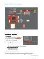
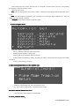
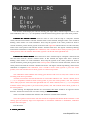
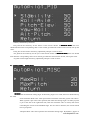
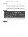
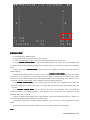
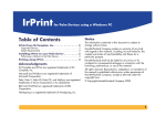
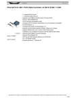
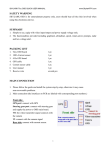
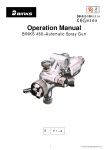
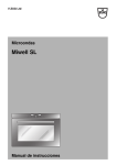
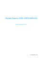
Skylark Dianmu OSD USER MANUAL
A skylark soars above the clouds.
www.SkylarkFPV.com
Dianmu OSD Connection diagram
AUTOPILOT SECTION
1. Connection
a. Install the sensor GPSINS horizontally
horizontally. The
cable connector should be placed toward the nose
nose..
b. According to the abovediagram,
PWM Input connect with RC receiver
Input 1 connect Aileron channel
Input 2 connect Elevator channel
Input 3 connect a 3-switch channel to switch autopilot mode
Input 4 connect a 3-switch channel to switch display mode
PWM output connect with servo
Output 1 connect Aileron servo
Output 2 connect Elevator servo
2. Keep the remote control in normal mode
In order to ensure the safe, please check all connections again before OSD power on.
3.
3.In
www.SkylarkFPV.com
After OSD power on
4.After
on,, the following menu would be shown:
shown::
System would detect the equipments that connected to the OSD control board automatically, then the
software & hardware version would be displayed.
Meanings of the information shown above:
HW
HW44.0 & SW
SW11.0
.0: represents hardware and software version are 4.0 and 1.0 respectively.
Logger
Logger: represents if the data logger is detected by the system. It flashes if the data logger is not
detected.
GPS
/INS
GPS/INS
/INS: represents if the GPS/INS is detected by the system. It flashes if GPS/INS is not detected.
RC CH IN
IN: is the RC receiver input channel
About 10 seconds after power connection, the system will enter one of the three modes. (It depends on
the switch status of the remote control.)
If the displayed information is different from the equipments connected, please check again before
take-off.
SOFTWARE SETTING
A After OSD initialization iscomplete
iscomplete,, the following menu would be shown:
www.SkylarkFPV.com
Select among the above items with the help of “Autopilot” channel switch, enter the corresponding
menu with the “Switch” channel switch.
Meaning of the menu:
Fly
ly: Enter the flying mode. If no action is taken, it would enter the flying mode automatically after a
while.
OSD
OSD: the OSD-related configuration page, including units, warnings, RSSI calibration etc. Enter the
OSD page when setting is needed.
Autopilot
utopilot: the Autopilot-related configuration page.
B.
B...Enter Autopilot menu.
Autopilot includes 5 sub-menu
Servos_Calibrate:Calibration input signal menu
Install_Relate:Installation setting menu
Control_PID:set the autopilot-related sensitivity
Control_MISC:miscellaneous setting, including the setting of maximum turning angle and safety
altitude etc.
Control_Safety:Safety parameters
Enter Install_Relate
menu to select airplane type;
C:
C:Enter
Install_Relatemenu
Tradition: is fixed wing, One port correspond one servo
Fly wing: is flying wing mode,1,2 channel will mix output.
Connect Aileron and Elevator servo
D:
D:Connect
Check the wing control output in manual mode
E. Servo_Calibrate Menu
Menu。
www.SkylarkFPV.com
The interface would display the real-time steering gear input values, with the range of -100 to +100.
After calibration, near 0 (< (+-5) is acceptable) would be shown when joystick is put in the center position.
Calibrate the “aileron
aileron”” channel
channel: Select the item of “Aile” with the help of “Autopilot” channel
switch, enter the menu with the “Switch” channel switch. At this moment, the figures after “Aile” would be
flashing, which means it is under calibration. First, keep the joystick in the center position for about 5
seconds. And then, put the aileron joystick to the end of the right-hand side for about 5 seconds. After that,
return to the center position and slide the “Switch” channel switch once. The figures would stop flashing,
which means calibration is completed. After calibration, near 0 would be shown when joystick is put in the
center position, near 100 would be shown when joystick is at the end of the right-hand side.
Calibrate the “Pitch
Pitch”” channel
channel: Select the item of “Elev” with the help of “Autopilot” channel switch,
enter the menu with the “Switch” channel switch. At this moment, the figures after “Elev” would be
flashing, which means it is under calibration. First, keep the joystick in the center position for about 5
seconds. And then, put the pitch joystick to the lowest position for about 5 seconds. After that, return to the
center position and slide the “Switch” channel switch once. The figures would stop flashing, which means
calibration is completed. After calibration, near 0 would be shown when joystick is put in the center
position, near 1000 would be shown when joystick is at the lowest position.
This calibration would calibrate the steering gear direction and travel as well, and it must be done
according to the above procedures.
And then, user needs to check if the direction is correct after calibration. For“aileron” channel, near 0
(< (+-5) is acceptable) would be shown when joystick is put in the center position, near 100 would be
shown when joystick is at the end of the right-hand side. For “Pitch” channel, near 0 (< (+-5) is acceptable)
would be shown when joystick is put in the center position, near 100 would be shown when joystick is at
the lowest position.
If the steering and displayed direction are inconsistent, then there would be an opposite control
direction. And the aircraft will turn over after entering the Balanced Mode
Mode.
There is no need to calibrate the “throttle” and “direction” channels at this moment.
Note: this operation must be done after the aircraft has completed the Manual Mode calibration. If the
steering gear has relatively large travel adjustment or mechanical calibration is undertaken, calibration
must be done once again.
Exit this menu.
F. Control_PID Menu
www.SkylarkFPV.com
Stability:Stabilization parameters
Roll_Aile:set the sensitivity for the aileron. If the aircraft vibrates in Balanced Mode
Mode, then user
should tune down the corresponding value. If user cannot get sufficient control for the aircraft, tune up the
value..
Pitch_Elev:set the elevator sensitivity, adjustment principle is same as above.
Yaw_Roll:set the sensitivity for the yaw. If the aircraft vibrates in Balanced Mode
Mode, then user should
tune down the corresponding value. If user cannot get sufficient control for the aircraft, tune up the value..
Alt_Pitch:set the height sensitivity, adjustment principle is same as above..
Control_MISC setting menu
G:C
MaxRoll
MaxRoll: Set the maximum rolling angle. If the turning angle is too small, then user should tune up
the value.
Semi-Automatic Mode: This value represents the maximum value that joystick can achieve.
When joystick is put in the center position, that means the turning angle is 0. When joystick
is put at the end of the right-hand side (reach the maximum value of 1000), that means
controlling the aircraft to the MaxRoll angle. For the value in between, the aircraft would
turn on proportion.
Autopilot Mode: This value represents the maximum turning angle. By default, 1 degree of
www.SkylarkFPV.com
turning deviation would be corrected by 1 degree of rolling angle.
MaxPitch
MaxPitch: Set the maximum pitching angle. If the climbing ability is not enough, then user should
tune up the value.
Semi-Automatic Mode: This value represents the maximum value that joystick can achieve.
When joystick is put in the center position, that means the pitching angle is 0. When
joystick is put at the lowest position (reach the maximum value of 1000), that means the
aircraft would climb in the MaxPitch angle. For the value in between, the aircraft would
climb on proportion.
Autopilot Mode: By default, when there is 10 meters of height deviation, the aircraft would
climb or descent in this pitching angle. Not to stall the aircraft, the value should not be too large.
H:Control_Safety
SecureAlt
SecureAlt: Set the safe Altitude. The setting is mainly used in the return flight. If the flying altitude
of the return flight is lower than this value, the aircraft would climb to the safe altitude.
If the flying altitude is higher than this value, the aircraft would keep flying with that
altitude.
Attitude indicator .
I:
I:Attitude
R:means Roll, Right roll is positive, left roll is negative
P:means Pitch, Nose-up is positive, otherwise it is negative
www.SkylarkFPV.com
FIELD TEST
A: Set the aircraft in Manual Mode
B: Adjust the travel and direction for the steering gear
C: Check the actual tilting angle is consistent with the displayed value in open area.
D: Enter Attitude Control Mode
Mode, check if the feedback direction is correct. If not, enter PWM menu
to confirm the joystick and display direction are consistent. If they are inconsistent, execute the calibration
again
E: Start flying under Manual Mode
Mode, observe the aircraft attitude is consistent with that shown in
infrared display.
F: When the aircraft flies above 50 meters, switch to the Attitude Control Mode and check the control
situation. [It is not suggested to use the infrared balancer under 50 meters because of the earth’s surface
interference.] If the aircraft vibrates, then user should tune down the corresponding value. Otherwise, user
can tune up the value and let OSD to have sufficient control in attitude balancing.
G: In Attitude Control Mode
Mode, put the Aileron joystick to the end of the right-hand side to check the
maximum rolling ability. If the rolling angle is too small, then user should tune up the MaxRoll value, and
vice versa.
H. In Attitude Control Mode
Mode, put the Elevator joystick to the maximum value and check the
maximum climbing & descending abilities. If the abilities are too weak, then user should tune up the
MaxPitch value, and vice versa.
I: Switch to Return Flight Mode from a short distance, observe the aircraft performances. Check if it
can control the flying attitude and hover for at least 5 laps.
J: If all above operations are under normal conditions, user can move on to the long distance return
flight.
K: If aircraft returns under normal conditions, user can set the waypoints and start flying.
Note
www.SkylarkFPV.com
The three-way switch of “Autopilot” represents:
is displayed on OSD, which is the Manual Mode
is displayed on OSD, which is the Attitude Control Mode
is displayed on OSD, which is the Return Flight Mode
If there are 4 or more GPS satellites and the take-off position has not been locked, user will find the
flashing icon
in Return Flight Mode.
If the GPS is not connected or there are less than 4 satellites, user will find the flashing icon
.
That means it is not allowed to enter the Return Flight Mode.
All the parameters would be overwritten after software upgrade, thus calibration must be executed once
again.
In Flying Mode, user can quit the OSD Details-mode (by sliding the “Switch” channel switch 3 times) and
enter the Configuration Mode for adjustment. The Configuration Mode can be entered only within 30
meters from the take-off point.
www.SkylarkFPV.com
About this publication
The information contained in this document is for reference purpose only, do not constitute the
warranty of any kind, experss or implied. It is subject to change or withdrawal according to specific
customer
requirements and conditions.
All the trademarks, pictures, and brands mentioned in this document are the property of Skylark FPV
Technologies Co., Ltd. or their respective holders.
Copyright ©2012 Skylark FPV Technologies Co., Ltd.
All rights reserved.
www.SkylarkFPV.com