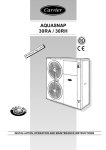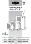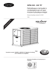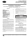
1
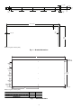
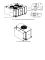
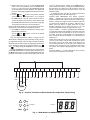
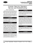
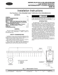
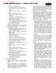
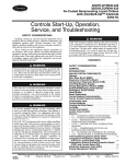
AquaSnap™ 30RA010-055
Accessory Low Ambient Operation
Motormaster® V Electronic Control
50/60 Hz
Installation Instructions
Part No: 30RA-900---006, 30RA-900---015, 30RA-900---016, 30RA-900---017,
30RA-900---018, and 30RA-900---019
CONTENTS
Page
GENERAL . . . . . . . . . . . . . . . . . . . . . . . . . . . . . . . . . . . . . . . . 1
SAFETY CONSIDERATIONS . . . . . . . . . . . . . . . . . . . . . . 1
PREINSTALLATION. . . . . . . . . . . . . . . . . . . . . . . . . . . . . . . 1
INSTALLATION . . . . . . . . . . . . . . . . . . . . . . . . . . . . . . . . . 1-8
Install Wind Baffles and Brackets . . . . . . . . . . . . . . . . 1
Control Mounting . . . . . . . . . . . . . . . . . . . . . . . . . . . . . . . . 5
Control Wiring . . . . . . . . . . . . . . . . . . . . . . . . . . . . . . . . . . . 5
Adjust the Configuration Jumper. . . . . . . . . . . . . . . . . 6
Configure Unit For Motormaster V
Electronic Control Operation. . . . . . . . . . . . . . . . . . . 6
Test the Motormaster V Electronic
Control Option Output . . . . . . . . . . . . . . . . . . . . . . . . . 6
START-UP . . . . . . . . . . . . . . . . . . . . . . . . . . . . . . . . . . . . . . .8,9
Low Ambient Application Notes . . . . . . . . . . . . . . . . . . 8
Motormaster V Control . . . . . . . . . . . . . . . . . . . . . . . . . . . 8
TROUBLESHOOTING. . . . . . . . . . . . . . . . . . . . . . . . . . . . 10
GENERAL
This book contains instructions for the installation and startup of the Motormaster V electronic low ambient control on
chiller models 30RA010-055.
This control varies condenser fan speed based on liquid
pressure. The control is a Variable Frequency Drive (VFD) and
is only compatible with motors rated for use with VFDs. The
accompanying pressure transducer has a 0 to 5 vdc output
range and a –40 to 460 psi range. The VFD provides a 5 vdc
output for the transducer on pin 6.
This system is a reverse acting, proportional-integral (PI)
control. The VFD will vary the motor speed to drive the liquid
line pressure to the set point during ambient temperatures
below 60 F (16 C). The set point is lower than a normal operating pressure during summer operation. At higher ambient
temperatures, the fan will go to full speed (60 Hz or 50 Hz
depending on model) and remain there since it can not go fast
enough to bring the pressure down to the set point. When the
VFD is at full speed, it acts just like a fixed speed fan.
When the ambient air temperature drops, a fan running at
full speed draws too much air across the condenser coil to
maintain a minimum condensing pressure/temperature. In
these conditions, the VFD will slow down and begin to maintain a set point.
The VFD will display the set point as the default. The set
point is displayed in speed as Hz and is configured by the start
command jumper.
Operating modes are configured for R-22 with a set point of
135 psig on the liquid line.
NOTE: The drive is phase insensitive in regard to incoming
line voltage. This means that the VFD will operate with any
phase sequence of the incoming three-phase voltage.
The standard outdoor-air temperature limitation of the Aquasnap chillers is 45 F (7.2 C) (sizes 010-018) and 32 F (0° C)
(sizes 022-055).
The Motormaster V electronic control low ambient operation kit can be used to extend the system operation down to
–20 F (28 C).
SAFETY CONSIDERATIONS
Be sure power to equipment is shut off before performing
maintenance or service.
Installing, starting up, and servicing air-conditioning equipment can be hazardous due to system pressures, electrical components and equipment location.
Only trained, qualified installers and service technicians
should install, start up, and service this equipment.
When working on air-conditioning equipment, observe precautions in the literature and on tags, stickers, and labels
attached to the equipment.
Follow all safety codes. Wear safety glasses and work
gloves. Use care in handling equipment.
PREINSTALLATION
Inspect the contents of the accessory package before installing. File a claim with the shipper if you find shipping damage
or contact your Carrier representative if any parts are missing.
See Tables 1A and 1B for kit package contents.
INSTALLATION
Install Wind Baffles and Brackets — Wind baffles
and brackets must be field fabricated and installed for all units
to ensure proper operation at low-ambient temperatures with
Motormaster V electronic controller. Unit sizes 010-030
require one baffle, sizes 032-055 require two baffles. See Fig. 1
and 2 for the sizes and details of brackets and baffles required.
See Fig. 3 and 4 for brackets and baffles location.
Use 14-gage galvanized sheet metal or similar corrosionresistant material for the brackets and 20-gage for the baffles.
Manufacturer reserves the right to discontinue, or change at any time, specifications or designs without notice and without incurring obligations.
PC 903
Catalog No. 533-00044
Printed in U.S.A.
Form 30RA-11SI
Pg 1
702
2-02
Replaces: 30RA-6SI
Book 2
Tab 5c
1.11 (28)
0.37 (9)
2.00
(51)
10.00 (254)
1.00
(25)
10.00 (254)
10.00 (254)
4.00
(102)
10.00 (254)
0.31
(8)
1.25
(32)
48.00 (1219)
0.50
(13)
0.50
(13)
0.50 (13)
18.00
(457)
Dimensions given in inches (mm).
Fig. 1 — Bracket Dimensions
A
O0.28 (7)
15 HOLES
10.00 TYP
(254)
10.00 TYP
(254)
48.00
(1219)
10.00 TYP
(254)
10.00 TYP
(254)
4.00 TYP
(102)
0.50 (13)
0.50 (13)
B
Dimensions given in inches (mm).
UNIT SIZE
DIM A
DIM B
30RAN010-018, 30RAN032-040 (circuit B side) 68.92 (1751) 34.46 (875)
30RAN022-030, 30RAN032-040 (circuit A side)
96.00 (2438) 48.00 (1291)
30RAN042-055
Fig. 2 — Baffle Dimensions
2
FAN A1
FAN B1
FAN A2
DETAIL B
SCALE 1:1
FAN B2
1.89
(48)
0.159 (4)
O 0.155 (4) (2) REQUIRED
SEE DETAIL A
O0.28
(7)
5.74 (146)
1.25 (32)
1.25 (32)
2.67 (68)
0.49
(12)
DETAIL A
SCALE 1:1
SEE DETAIL B
NOTE: Dimensions in inches (mm).
Fig. 3 — Typical Baffle Location Sizes 032-055 (042-055 Shown)
Fig. 4 — Baffle Location (Sizes 010-030)
3
Table 1A — Package Contents of Motormaster® V Control for 30RA010-030
30RA MODELS
VOLTAGES
MOTORMASTER V
ACESSORY PART NO.
208/230 V (60 Hz)
230 V (50 Hz)
30RA-900---006
380/415/460 V
50 & 60 Hz
30RA-900---015
575 V, 60 Hz
30RA-900---016
ITEM #
ITEM QTY
ITEM DESCRIPTION
ITEM PART NO.
1
2
3
4
5
6
7
8
9
1
2
3
4
5
6
7
8
9
1
2
3
4
5
6
7
8
9
1
8
1
1
1
1
1
1
1
1
8
1
1
1
1
1
1
1
1
8
1
1
1
1
1
1
1
Control
Mounting Screws
Control Box
Control Cover
Motor Plug Cable
Power Supply Cable
Transducer Connector
Pressure Transducer
Inrush Current Limiter
Control
Mounting Screws
Control Box
Control Cover
Motor Plug Cable
Power Supply Cable
Transducer Connector
Pressure Transducer
Inrush Current Limiter
Control
Mounting Screws
Control Box
Control Cover
Motor Plug Cable
Power Supply Cable
Transducer Connector
Pressure Transducer
Inrush Current Limiter
HR46TN001
AL56AU166
30RA500381
30RA500519
30RA400707
30RA400706
30RA400698
HK05YZ007
30RA401350
HR46TN002
AL56AU166
30RA500381
30RA500519
30RA400707
30RA400706
30RA400698
HK05YZ007
30RA401351
HR46TN003
AL56AU166
30RA500381
30RA500519
30RA400707
30RA400706
30RA400698
HK05YZ007
30RA401351
Table 1B — Package Contents of Motormaster V Control for 30RA032-055
30RA MODELS
VOLTAGES
MOTORMASTER V
ACCESSORY PART NO.
208/230 V (60 Hz)
230 V (50 Hz)
30RA-900---017
380/415/460 V
50 & 60 Hz
30RA-900---018
575 V, 60 Hz
30RA-900---019
ITEM #
1
2
3
4
5
6
7
8
9
10
11
1
2
3
4
5
6
7
8
9
10
11
1
2
3
4
5
6
7
8
9
10
11
ITEM
QTY
2
8
2
1
1
1
1
2
2
2
1
2
8
2
1
1
1
1
2
2
2
1
2
8
2
1
1
1
1
2
2
2
1
4
ITEM DESCRIPTION
ITEM PART NO.
Control
Mounting Screws
Mounting Screws
Motor Cable A1
Motor Cable B1
Power Cable, Fan A1
Power Cable, Fan B1
Transducer Connector
Pressure Transducer
Inrush Current Limiter
Current Limiter Mounting Bracket
Control
Mounting Screws
Mounting Screws
Motor Cable A1
Motor Cable B1
Power Cable, Fan A1
Power Cable, Fan B1
Transducer Connector
Pressure Transducer
Inrush Current Limiter
Current Limiter Mounting Bracket
Control
Mounting Screws
Mounting Screws
Motor Cable A1
Motor Cable B1
Power Cable, Fan A1
Power Cable, Fan B1
Transducer Connector
Pressure Transducer
Inrush Current Limiter
Current Limiter Mounting Bracket
HR46TN001
AL56AU166
AC41AB126
30RA401347
30RA401389
30RA400711
30RA400710
30RA400708,709
HK05YZ007
30RA401350
30RA501404
HR46TN002
AL56AU166
AC41AB126
30RA401347
30RA401389
30RA400711
30RA400710
30RA400708,709
HK05YZ007
30RA401351
30RA501404
HR46TN003
AL56AU166
AC41AB126
30RA401347
30RA401389
30RA400711
30RA400710
30RA400708,709
HK05YZ007
30RA401351
30RA501404
3. Install the pressure transducer on the 1/4-in. flare fitting
on the liquid line.
4. Plug the transducer connector from the side of the accessory into the pressure transducer.
Control Mounting
30RA010-030 — Mount the Motormaster® V electronic
control on the fan deck leg using the four screws provided as
shown in Fig. 5.
30RA032-055 — Insert the two inrush current limiter plugs
into the mounting bracket (30RA501345). Use the two screws
provided to mount the inrush current limiter bracket to the left
side of the control panel bottom in the pre-drilled holes. Mount
the Motormaster V electronic controls on the left side of
the control panel using the eight screws provided as shown in
Fig. 6.
30RA032-055: (See Fig. 6)
Circuit A: (30RA032-055)
1. Unplug the motor cable from the A1 motor at the contactor FC-A1. Using the A1 motor cable in the accessory
(30RA401347), connect the stripped leads marked ‘1,’
‘2’ and ‘3’ to the drive output terminals marked ‘T1,’
‘T2,’ and ‘T3.’ Route the plug end of this cable over to
the FC-A1 contactor and connect it to the A1 motor plug.
2. Using the A1 power cable in the accessory
(30RA400711), connect the stripped leads marked ‘1,’
‘2’ and ‘3’ to the drive input terminals marked ‘L1,’ ‘L2,’
and ‘L3.’ Route the plug at this end of the cable down to
the left inrush current limiter receptacle and connect.
Route the other end of this cable to the FC-A1 contactor
and connect it to the receptacle attached to the contactor.
3. Install the pressure transducer on the 1/4-in. flare fitting
on the Circuit A liquid line.
4. Route the transducer connector cable out the bottom of
the control panel and plug it into the pressure transducer.
Control Wiring
DO NOT connect incoming AC power to the output terminal T1, T2, and T3! Severe damage to the drive will result.
Hazard of electrical shock! Wait three minutes after disconnecting incoming power before servicing drive. Capacitors
retain charge after power is removed.
Circuit B: (30RA032-040)
1. Unplug the low speed motor cable, cable no. 1, at the
contactor FC-LS. Remove the plug from this cable. Strip
and wire nut the black, white and red leads together. Connect the ground wire to the control panel back.
2. Unplug the motor cable from the high-speed contactor
FC-HS. Using the B1 motor cable in the accessory
(30RA401389), connect the stripped leads marked ‘1,’
‘2’ and ‘3’ to the drive output terminals marked ‘T1,’
‘T2,’ and ‘T3.’ Route the plug end of this cable over to
the FC-HS contactor and connect it to the B1 high-speed
motor plug.
3. Using the B1 power cable in the accessory
(30RA400710), connect the stripped leads marked ‘1,’
‘2’ and ‘3’ to the drive input terminals marked ‘L1,’ ‘L2,’
and ‘L3.’ Route the plug at this end of the cable to the
right inrush current limiter receptacle and connect. Route
the other end of this cable to the FC-HS contactor and
connect it to the receptacle attached to the contactor.
4. Install the pressure transducer on the 1/4-in. flare fitting
on the Circuit B liquid line.
5. Route the transducer connector cable out the bottom of
the control panel and plug it into the pressure transducer.
DO NOT route the pressure transducer cable(s) with any of
the power wiring. Bundling the power and transducer wires
together can potentially cause interference and cause the
drive to operate improperly.
30RA010-018: TWO-SPEED MOTOR (See Fig. 7)
1. Unplug the low speed motor cable, cable no. 1, at the
contactor FC-LS. Unplug the other end of this cable from
the motor (low speed connection, right side of motor,
cable no. 1). This cable is no longer used.
2. Route the motor plug cable from the accessory to the motor and connect cable to the low speed connector. Verify
that the other end of this cable is connected to the shorting
plug (two short black jumper wires) at the bottom left of
the Motormaster V accessory.
3. Unplug the high-speed motor cable, cable no. 2, at the
contactor FC-HS. Remove this cable from the control
panel and connect it to the other plug at the bottom right
of the Motormaster V accessory. Verify that the wires
from this plug are connected to the T1, T2 and T3 output
terminals of the drive.
4. Route the power supply cable from the side of the accessory into the control panel and connect the plug to the
FC-HS contactor receptacle.
5. Install the pressure transducer on the 1/4-in. flare fitting
on the liquid line.
6. Plug the transducer connector from the side of the accessory into the pressure transducer.
Circuit B: (30RA042-055)
1. Unplug the motor cable from the B1 motor at the contactor FC-B1. Using the B1 motor cable in the accessory
(30RA401389), connect the stripped leads marked ‘1,’
‘2’ and ‘3’ to the drive output terminals marked ‘T1,’
‘T2,’ and ‘T3.’ Route the plug end of this cable over to
the FC-B1 contactor and connect it to the B1 motor plug.
2. Using the B1 power cable in the accessory
(30RA400710), connect the stripped leads marked ‘1,’
‘2’ and ‘3’ to the drive input terminals marked ‘L1,’ ‘L2,’
and ‘L3.’ Route the plug at this end of the cable to the
right inrush current limiter receptacle and connect. Route
the other end of this cable over to the FC-B1 contactor
and connect it to the receptacle attached to the contactor.
3. Install the pressure transducer on the 1/4-in. flare fitting
on the Circuit B liquid line.
4. Route the transducer connector cable out the bottom of
the control panel and plug it into the pressure transducer.
30RA022-030: Single Speed Motor (See Fig. 7)
1. Unplug the motor cable from the A1 motor at the contactor FC-A1. Remove this cable from the control panel
and connect it to the plug at the bottom right of the
Motormaster V accessory. Verify that the wires from this
plug are connected to the T1, T2 and T3 output terminals
of the drive. Do NOT make any connection to the shorting plug in the accessory for these sizes. Also, the motor
plug cable from the accessory is not used for these sizes.
2. Route the power supply cable from the side of the accessory into the control panel and connect the plug to the
FC-A1 contactor receptacle.
5
Adjust the Configuration Jumper — Depending on
the unit nameplate voltage, install the provided jumper on the
control terminal 2 to the proper location as listed in the Table 2.
NOTE: This jumper must be installed for the control to generate any output.
2. Press the ESCAPE key until the screen is blank and use
the arrow key to select the Configuration mode LED.
3. Press ENTER key, then use
key to select the submode ‘OPT1’, then press ENTER key.
4. Press
until ‘MMR.S’ displayed.
5. Press ENTER key twice. The word ‘PASS’ and
‘WORD’ will flash.
Table 2 — Configuration Jumper Location
UNIT
VOLTAGE
208-3-60
230-3-60
380-3-60
460-3-60
575-3-60
230-3-50
380-3-50
415-3-50
MOTORMASTER® V
CONTROL
PART NUMBER
HR46TN001
HR46TN001
HR46TN002
HR46TN002
HR46TN003
HR46TN001
HR46TN002
HR46TN002
CONFIGURATION
JUMPER
LOCATION
13A
1
13A
1
1
13B
13C
13C
6. Press 1 1 1 1 then ENTER key so that ‘NO’ flashes.
7. Use arrow keys to change to ‘YES’ and press ENTER
key.
8. Return the Enable/Off/Remote switch to the proper
position.
The chiller is now configured for Motormaster control.
Test the Motormaster V Electronic Control
Option Output — Follow the instructions given in the
Controls Start-Up, and Troubleshooting Guide to verify proper
operation of Motormaster V electronic control and the outdoorfan motors.
Configure Unit for Motormaster V Electronic
Control Operation — The unit must be configured for
the Motormaster V electronic control operation. Use the Scrolling Marquee display to configure the system as following:
1. Set the Enable/Off/Remote switch to OFF position.
DETAIL A
SENSOR LOCATION
A
Fig. 5 — Typical Control Mounting Location for Sizes 010-030 (Sizes 022-030 Shown)
6
7
702
CURRENT
LIMITERS AND
BRACKET MOUNTING
TO CIRCUIT A
TRANSDUCER
ON LIQUID LINE
PLUG FOR FAN
MOTOR A1
PLUG FOR
FAN MOTOR B1
TO CIRCUIT B
TRANSDUCER ON
LIQUID LINE
STRIP AND WIRE NUT
3 LEADS FROM FC-LS
PLUG CABLE TO LINE
SIDE OF MM-B1 HERE
ROUTE INTO CONTROL BOX MM-B1
TO NEC FUSED
DISCONNECT
→ Fig. 6 — Control Mounting Location and Wire Routing (Sizes 032-055)
ROUTE INTO
CONTROL BOX
TO MM-A1
PLUG FOR CABLE
TO LINE SIDE OF
MM-A1
FOR 2 SPEED MOTORS
CONNECT TO FC-HS
SIZES
032-040
The second fan is regulated by the ComfortLink control to
cycle between 156 and 243 psig discharge pressure.
INRUSH
CURRENT LIMITER
Motormaster V Control — The Motormaster V electronic control uses a 0 to 5 VDC signal input from a pressure
transducer attached to the liquid line service valve gage port on
each circuit. The pressure transducer is connected to terminals
2, 5 and 6 on the controller. The controller is factory configured
and requires no field programming. If drive does not function
properly, the information provided below and Table 3 can be
used to troubleshoot the drive.
If input power has not been applied to the drive for a period
of time exceeding three years (due to storage, etc.), the
electrolytic DC bus capacitors within the drive can change
internally, resulting in excessive leakage current. This can
result in premature failure of the capacitors if the drive is
operated after such a long period of inactivity or storage. In
order to reform the capacitors and prepare the drive for
operation after a long period of inactivity, apply input
power to the drive for 8 hours prior to actually operating
the motor. Before attempting to operate the drive, motor,
and driven equipment, be sure all procedures pertaining to
installation and wiring have been properly followed.
ATTACH JUMPER
WIRE PER TABLE 2
TO FAN
CONTACTOR
FC-HS POWER
PLUG
RECONNECT
HIGH SPEED
POWER (CABLE 2)
TO MOTOR
DO NOT connect incoming AC power to output terminals
T1, T2, and T3! Severe damage to the drive will result. Do
not continuously cycle input power to the drive more than
once every two minutes. Damage to the drive will result.
Hazard of electrical shock! Wait three minutes after disconnecting incoming power before servicing drive. Capacitors
retain charge after power is removed. Drive assembly
includes externally mounted current limiting resistors. Use
extreme caution when servicing the drive.
TO LOW SPEED FAN MOTOR CONNECTION
( 2 SPEED MOTORS ONLY)
Fig. 7 — Control Power Wiring (Sizes 010-030)
When configured as shown below, this equipment is
designed to start when it receives line power. Ensure that
all personnel are clear of fans and guards are installed
before applying power.
When the system calls for the fan, the fan contactor will be
energized to power the Motormaster® V electronic control. The
LED will display the speed of the motor. The display range will
be 8 to 50 Hz for 50 Hz units and 8 to 60 Hz for 60 Hz units.
The Motormaster V control will start the condenser fan
when the compressor engages. The control will adjust the fan
speed to maintain approximately 135 psig liquid line pressure.
Above that pressure, the fan should operate at full speed.
To test the control and motor, in the TEST mode, run any
compressor in each circuit. The Motormaster V electronic control adjusts the fan speed based on the liquid pressure input.
It is strongly recommended that the user NOT change any
programming without consulting Carrier service personnel.
Unit damage may occur from improper programming.
Motormaster V electronic control is configured according to
the inputs provided. No additional programming is necessary.
The drive can display 71 program parameters. Parameters
50-71 are monitor functions and cannot be changed. The
remainder of the parameters can be changed after entering a
password.
To enter password and change program values:
1. Press Mode button.
2. Upper right decimal point blinks.
START-UP
Low Ambient Application Notes
ONE-FAN CIRCUITS — The fan is equipped with a twospeed motor. ComfortLink™ controls call for high speed
operation when a compressor is engaged. The Motormaster V
device controls the fan speed to maintain the minimum head
pressure set point.
TWO-FAN CIRCUITS — The first fan will be controlled by
Motormaster V electronic control to maintain the minimum
discharge pressure.
8
viewed or changed before exiting). If the Mode button is
pressed within two minutes of exiting the PROGRAM mode,
the password is not required access the parameters. After two
minutes, the password must be entered in order to access the
parameters again.
To change password: first enter the current password then
change parameter P44 to the desired password.
LIQUID LINE PRESSURE SET POINT ADJUSTMENT — Adjusting the set point is not recommended due to
possible interaction with other head pressure software algorithms or controls. For single fan units or situations where the
set point must be changed, the set point is found in P34. A
higher value will result in a higher liquid line set point.
Example: Increasing the set point from 18.0 to 18.1 will
increase the liquid line pressure by approximately 10 psi.
FAULT CODES — The drive is programmed to automatically restart after a fault and will attempt to restart three times after
a fault (the drive will not restart after CF, cF, GF, F1, F2-F9, or
Fo faults). If all three restart attempts are unsuccessful, the
drive will trip into FAULT LOCKOUT (LC), which requires a
manual reset.
NOTE: Since faults may be reset as incoming power is cycled,
you may need to observe current fault code before the Carrier
unit control turns off the VFD. Most recent faults can be
accessed using parameter 50. If necessary, force condenser fan
contactor “ON” using Service Tool or jumper box and remove
start jumper. This will allow programming and access to fault
history.
MANUAL RESET — If fault condition has been removed,
cycle power to the chiller to reset the VFD.
3. Display reads “00” (see Fig. 9). To enter the PROGRAM
mode to access the parameters, press the Mode button
(see Fig. 9). This will activate the PASSWORD prompt
(if the password has not been disabled). The display will
read “00” and the upper right-hand decimal point will be
blinking.
4. Use the
and
buttons to scroll to the password
value (the factory default password is “111”) and press
the Mode button. Once the correct password value is
entered, the display will read “P01”, which indicates that
the PROGRAM mode has been accessed at the beginning
of the parameter menu (P01 is the first parameter).
NOTE: If the display flashes “Er”, the password was incorrect,
and the process to enter the password must be repeated.
5. Press Mode to display present parameter setting. Upper
right decimal point blinks.
Use the
and
parameter number.
buttons to scroll to the desired
Once the desired parameter number is found, press the
Mode button to display the present parameter setting. The upper right-hand decimal point will begin blinking, indicating
that the present parameter setting is being displayed, and that is
can be changed by using the up and down buttons. Use
and
to change setting. Press Mode to store new setting.
Pressing the Mode button will store the new setting and also
exit the PROGRAM mode. To change another parameter, press
the Mode button again to re-enter the PROGRAM mode (the
parameter menu will be accessed at the parameter that was last
1
2
5
COM
6
11
2
12
14
13A
13B
13C
15
25
2
30
31
TXA
+5V
Fig. 8 — Pressure Transducer and Start Command Configuration Jumper Wiring
DISPLAY
BUTTONS
Mode
Fig. 9 — Mode Buttons and Mode Display
9
TXB
TROUBLESHOOTING
• P52: DC BUS VOLTAGE — in percent of nominal.
Usually rated input voltage x 1.4
• P53: MOTOR VOLTAGE — in percent of rated output
voltage
• P54: LOAD — in percent of drives rated output current
rating
• P55: VDC INPUT — in percent of maximum input: 100
will indicate full scale which is 5 v
• P56: 4-20 mA INPUT — in percent of maximum input.
20% = 4 mA, 100% = 20 mA
Refer to Table 3 for more troubleshooting information.
Troubleshooting the Motormaster® V control requires a
combination of observing system operation and VFD information. The drive provides 2 kinds of troubleshooting modes: a
status matrix using the 3-digit display (P57, P58) and real time
monitoring of key inputs and outputs. The collective group
is displayed through parameters 50-71 and all values are
read-only. The key read-only outputs are:
• P50: FAULT HISTORY — Last 8 faults
• P51: SOFTWARE version
Table 3 — Fault Codes
FAULT CODE
AF
DESCRIPTION
High Temperature Fault: Ambient temperature is too high;
Cooling fan has failed (if equipped).
Control Fault: A blank EPM, or an EPM with corrupted data
has been installed.
Incompatibility Fault: An EPM with an incompatible parameter version has been installed.
SOLUTION
Check cooling fan operation
Perform a factory reset using Parameter 48 —
PROGRAM SELECTION.
Either remove the EPM or perform a factory
cF
reset (Parameter 48) to change the parameter
version of the EPM to match the parameter
version of the drive.
Data Fault: User data and OEM defaults in the EPM are
Restore factory defaults P48, see section
GF
corrupted.
above. If that does not work, replace EPM.
High DC Bus Voltage Fault: Line voltage is too high; Decel- Check line voltage — set P01 appropriately
HF
eration rate is too fast; Overhauling load.
Serial Fault: The watchdog timer has timed out, indicating
Check serial connection (computer)
JF
that the serial link has been lost.
Check settings for PXX
Check settings in communication software to
match PXX
Low DC Bus Voltage Fault: Line voltage is too low.
Check line voltage — set P01 appropriately
LF
Output Transistor Fault: Phase to phase or phase to ground Reduce boost or increase acceleration values.
OF
short circuit on the output; Failed output transistor; Boost
If unsuccessful, replace drive.
settings are too high; Acceleration rate is too fast.
Current Overload Fault: VFD is undersized for the applica- Check line voltage — set P01 appropriately
PF
tion; Mechanical problem with the driven equipment.
Check for dirty coils
Check for motor bearing failure
Single-phase Fault: Single-phase input power has been
Check input power phasing
SF
applied to a three-phase drive.
EPM Fault: The EPM is missing or damaged.
F1
Internal Faults: The control board has sensed a problem
Consult factory
F2-F9, Fo
Check for proper set point
Drive display = 60.0 even though Feedback signal is above set point
Check liquid line pressure
it is cold outside and it should
be running slower
Replace start jumper.
Drive display = ‘---’ even though Start jumper is missing
drive should be running
Check for proper set point
Drive display = 8.0 even though Feedback signal is below set point and fan is at minimum
speed
Check liquid line pressure
fan should be running faster
In stand alone mode: Check transducer wiring
VFD flashes 57 (60 Hz units), 47 Feedback or speed signal lost. Drive will operate at
57/47 Hz until reset or loss of start command. Resetting
and feedback voltage. Feedback voltage dis(50 Hz units) and LCS
requires cycling start command (or power).
played on P-69. Pin 6 should be 5 v output.
Pin 5 (feedback) should be somewhere
between 0 and 5 v.
1. Faulty pressure transducer output.
1. Check VDC signal between TB5 and TB2.
VFD not slowing down even
Should be in range of 0.5 v to 4.5 v.
though liquid line pressure is
2. VFD set for manual control.
2. Restore VFD to automatic control. Change
below set point.
Parameter P05 back to correct value
shown in Table 2.
CF
EPM
LCS
OEM
LEGEND
— Electronic Programming Module
— Loss of Control Signal
— Original Equipment Manufacturer
10
Copyright 2002 Carrier Corporation
Manufacturer reserves the right to discontinue, or change at any time, specifications or designs without notice and without incurring obligations.
PC 903
Catalog No. 533-00044
Printed in U.S.A.
Form 30RA-11SI
Pg 12
702
2-02
Replaces: 30RA-6SI
Book 2
Tab 5c