1
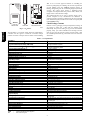
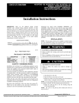
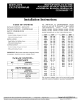
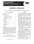
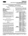
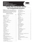
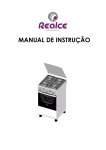
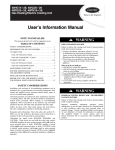
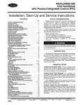
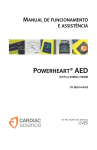
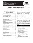
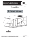
CRCBDIOX001B00
48/50PD05–06, 48/50HG014–028,
48/50PG03---28, 48/50PM16---28
CO2 Sensor Accessory
Single Package Rooftop Units
with COMFORTLink™ Controls
Installation, Start--Up and
Service Instructions
TABLE OF CONTENTS
SAFETY CONSIDERATIONS
PACKAGE CONTENTS . . . . . . . . . . . . . . . . . . . . . . . . . . . . . . 1
Installation and servicing of air--conditioning equipment can be
hazardous due to system pressure and electrical components. Only
trained and qualified service personnel should install, repair, or service air--conditioning equipment.
When working on equipment, observe precautions in the literature,
tags and labels attached to the unit, and other safety precautions
that may apply.
Follow all safety codes. Wear safety glasses and work gloves.
SAFETY CONSIDERATIONS . . . . . . . . . . . . . . . . . . . . . . . . . 1
GENERAL . . . . . . . . . . . . . . . . . . . . . . . . . . . . . . . . . . . . . . . . . 1
INSTALLATION . . . . . . . . . . . . . . . . . . . . . . . . . . . . . . . . . . . . 3
START--UP . . . . . . . . . . . . . . . . . . . . . . . . . . . . . . . . . . . . . . . . . 5
SERVICE . . . . . . . . . . . . . . . . . . . . . . . . . . . . . . . . . . . . . . . . . . 5
TROUBLESHOOTING . . . . . . . . . . . . . . . . . . . . . . . . . . . . . . . 5
IMPORTANT: Read and become familiar with all instructions
before beginning installation of CO2 sensor accessory.
IMPORTANT: There are two different design revision 48/50HG
units currently being produced. Because of these differences, there
are two different versions of this accessory. This accessory
literature covers accessories manufactured for units with design
revision 1. Design revision 0 units are not covered in this accessory
book. To determine the design revision, refer to the full unit model
number. See Fig. 1 for an example of an HG model number. The
design revision number in the model number nomenclature is
located in position 13.
!
DESIGN REVISION NUMBER
Position No.
1
2
3
4
5
6
7
8
9
10 11 12 13 14 15
16
Example:
4
8
H
G
D
0
1
6
A
A
A
C
.
Recognize safety information. This is the safety--alert symbol
When you see this symbol on the unit and in instructions or manuals, be alert to the potential for personal injury.
Understand the signal words DANGER, WARNING, and CAUTION. These words are used with the safety--alert symbol. DANGER identifies the most serious hazards which will result in severe
personal injury or death. WARNING signifies a hazard which
could result in personal injury or death. CAUTION is used to identify unsafe practices which may result in minor personal injury or
product and property damage. NOTE is used to highlight suggestions which will result in enhanced installation, reliability, or operation.
6
1
1
A
C07172
Fig. 1 -- Model Number Chart
PACKAGE CONTENTS
PART NUMBER
DESCRIPTION
QUANTITY
HH99ZZ009
CO2 Sensor
1
HH99ZZ015
Enclosure
1
AL56AU166
Screw --- No. 8 x 1/2 ---in.
4
50TG403323
Unit Wiring Harness
(48/50HG014 ---028,
48/50PG20 ---28,
48/50PM16 ---28)
1
48HG400595
Unit Wiring Harness
(48/50PG03 ---16,
48/50PD05 ---06)
1
50TG403368
Sensor Wiring Harness
1
HY93NH069
Snap Bushing
2
HY76TB110
Wire Tie
2
Copyright 2009 Carrier Corp. D 7310 W. Morris St. D Indianapolis, IN 46231
ELECTRICAL
HAZARD
WARNING
SHOCK,
FIRE
AND
EXPLOSION
Failure to follow this warning could result in personal injury,
death or property damage.
Before performing service or maintenance operation on unit,
turn off main power switch to unit. Shut off gas supply before
shutting off main power. Tag gas shut off and power
disconnect switch with a suitable warning label.
GENERAL
The CO2 Sensor (Fig. 2) is designed to monitor carbon dioxide
(CO2) levels in the return air and interface with the ComfortLinkt
controller on the rooftop air-conditioning unit. The sensor
perceives CO2 levels in the 0 to 2,000 parts per million (ppm)
range and provides outputs indicating this level.
Printed in U.S.A.
Edition Date: 11/09
Manufacturer reserves the right to change, at any time, specifications and designs without notice and without obligations.
Catalog No:IIK---CRCBDI01---02
Replaces: IIK--- CRCBDI01--- 01
This is one of several approved methods of controlling the
indoor-air quality (IAQ) in a building and meets the requirements
of local building codes and ASHRAE (American Society of
Heating, Refrigerating and Air Conditioning Engineers) Standard
62-1999. The control sensor features a membrane-covered
waveguide and sample chamber that produces stable, reliable, and
highly accurate carbon dioxide readings.
The standard RS-232 port is used to interface directly with a
personal computer for easy customization and calibration. A
software program is required for calibration of the sensor. The UIP
(User Interface Program) and RS-232 serial cable are required (P/N
CGCDXPRM001A00).
Check Package Contents
SIDE VIEW
FRONT VIEW
MOUNTING PLATE
C09547
CRCBDIOX
Fig. 2 -- CO2 Sensor
The unit utilizes a 4 to 20-mA analog signal. The ComfortLinkt
controller uses this signal to control the economizer damper
position and ensure an adequate level of outside air in the building.
Remove accessory packaging and inspect shipment for damage. If
any damage is found, file a claim with the shipping agent
immediately. If any item is missing or any part does not assemble
properly, notify your Carrier distributor. The Package Contents
table on page 1 lists the accessory package contents. Table 1 lists
the controller specifications. Fig. 3 shows the CO2 sensor enclosure
dimensions.
Table 1 – CO2 Specifications
ACCURACY
At Constant Temperature (78_F)
20 ppm (also repeatability)
± 2.5% of reading or
± 50 ppm whichever is greater
± 5.0% of reading or
± 100 ppm whichever is greater
± 0.05% of reading
0.19% per mm hg
<20 ppm with TEMA Self Calibration Feature
± 100 ppm
< 1 min.
< 6 min.
Typical Conditions (60_ to 90_F) (16_ to 32_C)
Extended Conditions (32_ to 145_F) (0° to 63_C)
Percent Change in Reading per °F
Pressure Dependence
Annual Drift
Maximum Drift (per year)
Response Time (at 500 ml/min.)
Warm-up Time at 72_F (at 22_C)
GENERAL PERFORMANCE
Operating Principle
Gas Sampling Mode
EMI Interface
Certification
Shock Resistance
Sensor Life
Data Interface
Alarm Threshold Adjust Range
Alarm Threshold Adjust Resolution
Alarm Threshold Hysteresis
Calibration Adjustments
Calibration Procedure
Recommended Calibration Interval
Operating Temperature Range
Storage Temperature Range
Operating Humidity Range
Operating Pressure Range
Dimensions (L x W x D)
Weight
Power Input
Isolation Transformer
OUTPUT
Optional Display
Non-dispersive infrared (NDIR)
Diffusion
FCC Part 15 Class B
By the California Energy Commission
40 Gs
15 years
Via RS-232 serial port
50 to 50,000 ppm, programmable
± 20 ppm
50 ppm
Zero and span via RS-232 serial port
Automated with UIP
One Year
32_ to 113_F (0° to 45_C)
–40_ to 158_ F (–40_ to 70_C)
0 to 95% RH (non-condensing)
± 1.5% local mean pressure
6.4 x 2.2 x 1.7 in. (16.3 x 5.6 x 4.3 cm)
16 oz (454 gm)
Nominal 24 vac (50/60 Hz)
Not required with half-wave rectification
4-digit green LED display
0 to 10 v or 4 to 20 mA (jumper selected on
circuit board)
Can be set to any output within maximum range using PC-based UIP
Fully adjustable using PC-based program and RS-232 interface. Max:
0 to 2,000 ppm
Gold bifurcated, 2 A rating, close on CO2 rise
100 mW max (measured at 6 v DC, 0.1 A)
Set point and deadband via PC-based UIP
300 mA average, 500 mA peak
16 to 20 gauge stranded wire
Analog Output Maximum Range
Analog Output Customization
Measurement Range
Relay
Relay Contact Resistance
User Relay Adjustments
Current Requirements
Wiring Requirements
LEGEND
TEMA
--UIP
---
Time Extended Measurement Algorithm
User Interface Program
2
1 1/8”
2 1/16”
1” TYP
13/16”
1 3/16”
1 3/16”
TOP
1 3/16”
5/16”
4 5/16”
13/16”
2.00”
1 3/16”
1 3/16”
2 13/16”
11/16”
1 3/16”
1” TYP
1 7/8”
7 1/8”
3 9/16”
4 11/16”
3 9/16”
1 3/16”
5 7/16”
5 9/16”
7 1/8”
TUBE ROTATED 90°
FOR CLARITY
1 1/2”
1 3/16”
1/4” DIA
4 HOLES
SIDE
C09548
Fig. 3 -- CO2 Sensor Enclosure Dimensions
8. Remove plastic plug from economizer partition. Mount
enclosure box to the partition using 4 sheet metal screws,
verifying that the 3 cutouts on the inlet tube are facing
downward as shown in Fig. 6.
9. Caulk the snap bushing to make sure that the box is
completely sealed.
10. Attach sensor to the mounting plate.
11. Route unit wiring harness (P/N 48HG400595) through
patch plate on economizer. (See Fig. 4.) Continue running
harness with economizer harness, using metal clips and wire
ties along top of filter plate. Be sure to leave enough slack
so economizer can be tilted out.
12. Remove grommet from compressor partition and route
harness through the slot. Replace grommet.
13. Open compressor access panel and locate end of harness.
Wire the electrical harness (P/N 48HG400595) to the
terminal strips as shown in Fig. 5.
14. Because the return air sensor is at a static zero or negative
pressure, relative to ambient air, it is vital that the box be
completely sealed. This includes areas where the control
wiring enters the box and the perforated tubing enters the
box. Once the enclosure is mounted, the return air will enter
the inlet holes of the perforated tube, circulate through the
sensor chamber and exhaust through the exit slots on the
other side of the tube.
15. Connect the ends of the plug (PL18) together. Secure wires
so they do not interfere with normal operation.
16. Close and secure the economizer panel and replace the
Plexiglas cover.
17. Restore power to unit.
PL18
PATCH PLATE IN ECONOMIZER ASY
ROUTE HARNESS PL18 THRU
CO2 SENSOR ASSEMBLY
C09549
Fig. 4 -- CO2 Sensor Location in 48/50PD05--06
and 48/50PG03--16 Units
INSTALLATION
48/50PD05--06 and 48/50PG03--16
The CO2 sensor is to be installed in the pre--drilled holes located in
the economizer block as shown in Fig. 4.
1. Shut off unit power supply.
2. Open the hinged economizer door and secure.
3. Prepare the sensor enclosure (P/N HH99ZZ015) for
mounting by removing the 4 screws on the Plexiglas
cover.
4. Remove the CO2 sensor (P/N HH99ZZ009) from the
mounting plate.
5. Attach mounting plate to standoffs in the enclosure using
the 4 machine screws.
6. Hold the enclosure vertically with the terminal blocks at the
bottom and install a snap bushing in the conduit hole
located on the right-hand side of the enclosure at the top.
7. Wire the sensor wiring harness (P/N 50TG403368) to the
sensor as shown in Fig. 5. Be sure to route the wires
through the bottom of the mounting plate and the snap
bushing.
3
CRCBDIOX
3 9/16”
5 7/16”
J8
J7
2
1
8
7
6
5
4
3
2
1
PL18
BLK
RED
RED
BLU
BRN
BLK
BLU
BRN
CO2 SENSOR
CO
2 SENSOR
CRCBDIOX
C09550
Fig. 5 -- Wiring Diagram
CO2 SENSOR
TB2
ORIENT SAMPLING TUBE SO THAT
THE HOLES POINT DOWN.
C09551
Fig. 6 -- Economizer Block Off
C09552
Fig. 7 -- CO2 Sensor Location in
48/50HG014--028, 48/50PG20--28 Units
48/50HG014--024, 48/50PG20--28 and
48/50PM16--28
9. Caulk the snap bushing to make sure that the box is
completely sealed.
10. Attach sensor to the mounting plate.
11. Install the snap bushing in the center knockout underneath
the control terminal strips located in the bottom right-hand
corner of the control box.
12. Wire the electrical harness (P/N 50TG403323) to the
terminal strips as shown in Fig. 5. Connect the ends of the
plug (PL18) together. Secure wires so they do not interfere
with normal operation.
13. Because the return air sensor is at a static zero or negative
pressure, relative to ambient air, it is vital that the box be
completely sealed. This includes areas where the control
wiring enters the box and the perforated tubing enters the
box. Once the enclosure is mounted, the return air will enter
the inlet holes of the perforated tube, circulate through the
sensor chamber and exhaust through the exit slots on the
other side of the tube.
14. Re--attach the Plexiglas cover.
15. Restore power to unit.
The CO2 sensor is to be installed in the pre--drilled holes located
above compressor C1 location in the Electrical/Compressor
Section. (See Fig. 7.) If the unit does not have a third compressor,
the sensor will still be installed above where the third compressor
would be.
1. Shut off unit power supply.
2. Open the hinged Electrical/Compressor door and secure.
3. Prepare sensor enclosure (P/N HH99ZZ015) for mounting
by removing the 4 screws on the Plexiglas cover.
4. Remove the sensor CO2 (P/N HH99ZZ009) from the
mounting plate.
5. Attach mounting plate to standoffs in the enclosure using
the 4 machine screws.
6. Hold the enclosure vertically with the terminal blocks at the
bottom and install a snap bushing in the conduit hole
located on the right-hand side of the enclosure at the top.
7. Wire the sensor wiring harness (P/N 50TG403368) to the
sensor as shown in Fig. 5. Be sure to the route the wires
through the bottom of the mounting plate and the snap
bushing.
8. Mount enclosure box to the partition using 4 sheet metal
screws, verifying that the 3 cutouts on the inlet tube are
facing down and that the terminal blocks are located at the
bottom.
4
START-UP
Configuring the ComfortLinkt Controller
The CO2 sensor is defaulted to provide 4 mA at 0 ppm and 20 mA
at 2000 ppm. If a different range is necessary, the User Interface
Program (UIP) accessory (P/N CGDXPRM001A00) must be used
to reconfigure the sensor. If the sensor is reconfigured, the mA
range on the ComfortLink controller must be configured to match
the new values.
ComfortLink configurations are changed by using the Scrolling
Marquee display. A password may be required to edit the
configurations, depending on the previous settings configured in
the unit. Default password is “1111”. All configurations can be
changed by using the arrow keys to scroll the red LED on the
display to the “Configuration” position and press ENTER . Scroll
through the menu until IAQ is found and press ENTER . After
reaching the IAQ sub-menu, all configurations can be changed by
finding the desired configuration by scrolling, pressing ENTER
twice, changing the value with the arrow keys, pressing ENTER
once and then pressing ESCAPE . Once one configuration has
been changed, the remaining configurations can be changed by
repeating the above steps. The configurations are listed in Table 2.
Cleaning
The controller is a rugged and lightweight unit that requires very
little maintenance. Clean external surfaces periodically with a
dampened cloth.
TROUBLESHOOTING
The following occurrences may indicate abnormal operation,
caused primarily by power input fluctuations, surges, or spikes.
S The unit remains in warm-up mode for more than 10 minutes.
S The LED glows with no pulse.
S CO2 indication (display numbers or signal output) is frozen.
S Numbers on the display change continuously for longer than 1
minute.
Normal operation can usually be restored by removing power,
shutting down the unit for at least 15 seconds, then
reconnecting power. The unit should warm up, as described above,
then return to normal operation. If the situation continues, remove
and replace the sensor.
For additional troubleshooting information, see Controls and
Troubleshooting Guide for Centurion unit.
Verification and Calibration
The control can be verified for accuracy or calibrated with the
accessory IAQ Calibration Kit. It is recommended that the user
verify and/or calibrate the unit at least once a year. Contact a
Carrier representative to obtain the accessory calibration kit.
Calibration Kit (P/N CGCDXGAS001A00) includes:
S Calibration Adapter Blanket (CAB)
S Tygon® Tubing
S Clip Retainers
S Bottle of N2 Gas (0 ppm CO2)
S Bottle of CO2 Gas (~2,000 ppm) in Nitrogen
S Pressure-Regulator Valve
S User Interface Program (UIP) Disk (3.5 in.) (Version 3.0)
S RS-232 Serial Cable
NOTE: The UIP is used for interfacing the controller with an
IBM® PC, or equivalent. The UIP uses the DOS operating system
and is menu driven.
5
CRCBDIOX
After applying power, the CO2 sensor will enter a warm-up mode,
indicated by the word ‘‘HEAT’’ in green on the display. Warm-up
duration will be from 1 to 10 minutes. The warm-up duration will
be shorter in warmer temperatures and longer in cooler
temperatures. During warm-up, the signal output will be 4 mA.
Once the unit has warmed up, the voltage or current output will be
set up to indicate the CO2 level. The display will show a steady
reading 1 minute later.
SERVICE
CRCBDIOX
Table 2 – IAQ Configurations
ITEM
IA.CF
EXPANSION
IAQ Analog Input Configuration
IA.FN
Fan Enable for Analog IAQ Input
II.CF
IAQ Switch Input Configuration
II.FN
Fan Enable for Switch IAQ Input
AQ.MP or
AQ.MN
MIN.P or
EC.MN
Minimum IAQ Position
Economizer Min Position
DESCRIPTION
Control method to be used for analog input.
0: No IAQ
1: Demand Control Ventilation (DCV)
2: Override IAQ
3: Control Minimum Position
Indicates whether the indoor fan must be operating before IAQ can operate.
0: Never
1: Occupied
2: Always
Control method used for switch input.
0: No IAQ
1: Demand Control Ventilation (DCV) — Normally Open
2: Demand Control Ventilation (DCV) — Normally Closed
3: Override IAQ — Normally Open
4: Override IAQ — Normally Closed
Indicates whether the indoor fan must be operating before IAQ can operate.
0: Never
1: Occupied
2: Always
Damper position necessary to remove contaminants and CO2 from
sources other than people.
Damper position necessary to remove contaminants and CO2 from all
sources including people. This is the design value for maximum occupancy.
Position when economizer is in Override IAQ
DEFAULT
0
600 PPM
200 PPM
OVR.P
Economizer Position
OA.CF
OAQ Sensor Operation
AQD.L
AQ Differential Low
AQD.H
AQ Differential High
OAQ.L
OAQ Lockout Value
DF.ON
Fan On AQ
0: No OAQ
1: OAQ is used in DCV calculations
2: OAQ is used to lockout IAQ.
Differential AQ value above Outdoor Air Quality (OAQ) when the building
is “occupied” but no was has arrived and the economizer should be at
AQ.MP. When the differential between IAQ and OAQ begins to exceed
AQD.L, the economizer will begin to open from AQ.MP, moving towards
MIN.P.
If an OAQ sensor is not installed, the default value is 400 PPM.
Differential AQ value above Outdoor Air Quality (OAQ) when the building
is fully occupied and the economizer should be at MIN.P. When the differential between IAQ and OAQ is less than AQD.H, the economizer will begin to close from MIN.P, moving towards AQ.MP.
If an OAQ sensor is not installed, the default value is 400 PPM.
If OAQ is greater than OAQ.L, then the economizer will not try to control
IAQ and it will operate at AQ.MP.
Differential needed to turn on indoor fan if specified by IA.FN or II.FN
DF.OF
Fan Off AQ
Differential needed to turn off indoor fan if specified by IA.FN or II.FN
I.4M
IAQ Sensor Value at 4 mA
PPM corresponding to 4 mA from the IAQ CO2 sensor.
I.20M
IAQ Sensor Value at 20 mA
PPM corresponding to 20 mA from the IAQ CO2 sensor.
O.4M
OAQ Sensor Value at 4 mA
PPM corresponding to 4 mA from the OAQ CO2 sensor.
O.20M
OAQ Sensor Value at 20 mA
PPM corresponding to 20 mA from the OAQ CO2 sensor.
6
0
0
0
0
10%
30%
100%
100 PPM
700 PPM
600 PPM
0 PPM
2000 PPM
0 PPM
2000 PPM