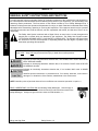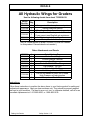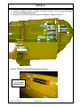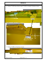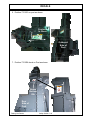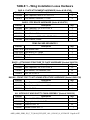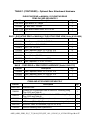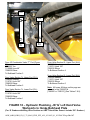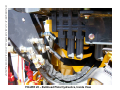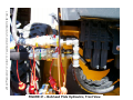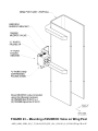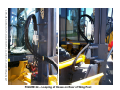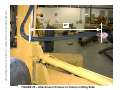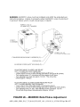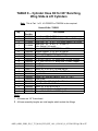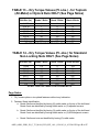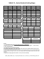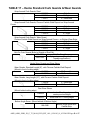
1
HENKE ALL-HYDRAULIC WING AHW 42BH & 66BH, JD G T4 FOR JOHN DEERE “G” SERIES GRADERS with JD MANUAL HYDRAULICS (Grade Pro Not Included) Serial Number: _______________ PARTS BOOK AND INSTALLATION MANUAL VERSION 3.2, APRIL 2015 HENKE MANUFACTURING CORPORATION MANUFACTURERS OF SNOW REMOVAL EQUIPMENT FOR 95 YEARS 3070 WILSON AVE. LEAVENWORTH, KS 66048 PHONE (913)682-9000 FAX(913)682-0300 WEBSITE ADDRESS : WWW.HENKEMFG.COM EMAIL: [email protected] AHW_66BH_42BH_JD_G_T3_MAN_HYD_EFF_ALL_8510103_01_032.DOCX <THIS PAGE IS INTENTIONALLY LEFT BLANK> AHW_66BH_42BH_JD_G_T3_MAN_HYD_EFF_ALL_8510103_01_032.DOCX Page 2 of 47 Introduction Thank you for your purchase of a H enke All Hydraulic Wing for your John Deere “G” Series motor grader. T he bolt-up/bolt-up attaching structure design of t his wing allows greater ro tation of the main grader blade than other designs, which improves snow mo ving capability. The All Hydraulic Wing consists of four main subassemblies: 1. Wing Post and Attachment Assemblies 2. Moldboard and Pushbeam Assemblies 3. Rear Attachment Assembly (e ither: Elevating Rear, Fixed Rear, Manually Elevating Rear, or Rear Ripper Attachment) 4. Hydraulic Hoses and Fittings Before beginning your installation, please check that all of the appropriate ship-loose parts and hardware listed in Table 1 was received. In the unlikely event that any parts are mi ssing, please contact Henke Manufacturing Corporation for replacements. The cutting path, defined as the dist ance perpendicular to the motion of the vehicle, of the s now wing is approximately 80% of the moldboard length. Therefore, an AHW-12’ would hav e a cutting path of almost 10 feet. The parts lists for the AHW JD “G” s now wing are listed in Tables 2 thru 12 (if applicable). These lists are important and should be referred to when ordering replacement parts fr om your local dealer or Henk e Manufacturing Corporation. The parts diagrams for the snow wing ar e shown in Figures 1 thru 7. This Product Manual should be read in its entirety bef ore using your Henke AHW JD “G” snow wing to minimize mounting problems. For customer service, replacement parts, or answers to questions about your Henke plow, please call Henke Manufacturing at (913) 682-9000. AHW_66BH_42BH_JD_G_T3_MAN_HYD_EFF_ALL_8510103_01_032.DOCX Page 3 of 47 Table of Contents Introduction ..................................................................................................................... 3 Safety Information (Section 1-1 thru 1-15) ...................................................................... 6 In Season Maintenance................................................................................................... 7 End of Season Maintenance ........................................................................................... 8 Henke Standard Warranty Policy .................................................................................. 44 Dealer Warranty Policy.................................................................................................. 45 List of Tables Table 1 - Wing Installation Loose Hardware.................................................................... 9 Table 2 - Front Post Assembly & Attachments, Parts List ............................................. 12 Table 3 - AHW Moldboard Assembly & Attachments, Parts List ................................... 14 Table 4 - AHW Elevating Rear Assembly, Parts List ..................................................... 16 Table 5 - Fixed Rear Assembly, Parts List .................................................................... 19 Table 6 - Manually Elevating Rear Assembly, Parts List ............................................... 20 Table 7 - Parts List – Cylinder Hose Kit, Part 1 of 2 (7082051) ..................................... 38 Table 8 - Parts List – Cylinder Hose Kit, Part 2 of 2, JD G LEFT (7082003) ................. 39 Table 9 - Parts List – Cylinder Hose Kit, Part 2 of 2, JD G RIGHT (7082004)............... 39 Table 10 - Parts List – Elevating Rear Hose Kit ............................................................ 39 Table 11 - Torque Values for Toplock or Nylock Nuts ................................................... 40 Table 12 - Torque Values for Non-Locking Nuts ........................................................... 40 Table 13 - Henke Standard Cutting Edges .................................................................... 41 Table 14 - Henke Standard Cutting Edge Hardware ..................................................... 42 Table 15 - Henke Standard Curb Guards & Wear Guards ............................................ 43 AHW_66BH_42BH_JD_G_T3_MAN_HYD_EFF_ALL_8510103_01_032.DOCX Page 4 of 47 List of Figures FIGURE 1 - All Hydraulic Wing with Fixed Rear on JD 770G ...............................COVER FIGURE 2 - Post Assembly & Attachments................................................................... 11 FIGURE 3 - Moldboard Assembly & Attachments ......................................................... 13 FIGURE 4 - Elevating Rear Assembly (Optional) .......................................................... 15 FIGURE 5 - Rear Ripper Ear Assy. (Optional) .............................................................. 17 FIGURE 6 - Fixed Rear Assembly (Standard) ............................................................... 18 FIGURE 7 - Manually Elevating Rear (Optional) ........................................................... 19 FIGURE 8 - Rear Ripper Assembly ............................................................................... 20 FIGURE 9 - Manually Elevating Rear Views ................................................................. 21 FIGURE 10- Front Post Frame Ready Plate Mounting.................................................. 22 FIGURE 11 - Front Post & Attaching Structure Mounting.............................................. 23 FIGURE 12 - Pipe Brace Installation ............................................................................. 24 FIGURE 13 - Pipe Brace Attachment to Grader ............................................................ 25 FIGURE 14 - Notching of Top Cover ............................................................................. 26 FIGURE 15 - Hydraulics Schematic, from Bulkhead Plate to Wing ............................... 27 FIGURE 16 - Hydraulics, ‘G’ Grader Workports (Right) to Bulkhead Plate ................... 28 FIGURE 17 - Hydraulics, ‘G’ Grader Workports (Left) to Bulkhead Plate ...................... 29 FIGURE 18 - Tie-In to Return Circuit of Grader ............................................................ 30 FIGURE 19 - Bulkhead Plate Hydraulics, Inside View................................................... 31 FIGURE 20 - Bulkhead Plate Hydraulics, Front View. ................................................... 32 FIGURE 21 - Hydraulic Attachment at Bulkhead Plate.................................................. 33 FIGURE 22 - Mounting of MUDROC Valve on Wing Post............................................. 34 FIGURE 23 - Looping of Hoses on Rear of Wing Post .................................................. 35 FIGURE 24 - Attachment of Hoses to Clamp on Wing Slide Assembly......................... 36 FIGURE 25 - MUDROC Relief Valve Adjustment ......................................................... 37 AHW_66BH_42BH_JD_G_T3_MAN_HYD_EFF_ALL_8510103_01_032.DOCX Page 5 of 47 <THIS PAGE IS INTENTIONALLY LEFT BLANK> AHW_66BH_42BH_JD_G_T3_MAN_HYD_EFF_ALL_8510103_01_032.DOCX Page 6 of 47 SAFETY SECTION Safety Section 1-1 © 2009 Alamo Group Inc. SAFETY GENERAL SAFETY INSTRUCTIONS AND PRACTICES SAFETY A careful operator is the best operator. Safety is of primary importance to the manufacturer and should be to the owner/operator. Most accidents can be avoided by being aware of your equipment, your surroundings, and observing certain precautions. The first section of this manual includes a list o f Safety Messages that, if followed, will help protect the operator and bystanders from injury or death. Read and understand these Safety Messages before assembling, operating or servicing this Implement. This equipment should only be operated by those persons who have read the manual, who are responsible and trained, and who know how to do so responsibly. The Safety Alert Symbol combined with a Signa l Word, as se en below, is use d throughout this manual and on decals which are attached to the equipment. The Safety Aler t Symbol means: “ATTENTION! BECOME ALERT! YOUR SAFETY IS INVOLVED!” The Symbol and Signal Word are intended to warn the owner/operator of impending hazards and the degree of possible injury faced when operating this equipment. Practice all usual and customary safe working precautions and above all---remember safety is up to YOU. Only YOU can prevent serious injury or death from unsafe practices. Indicates an imminently hazardous situation that, if not avoided, WILL result in DEATH OR VERY SERIOUS INJURY. Indicates an imminently hazardous situation that, if no t avoided, COULD result in DE ATH OR SERIOUS INJURY. Indicates an imminently hazardous situation that, if not avoided, MAY result in MINOR INJURY. Identifies special instructions or procedures that, if no t strictly observed, could result in damage to, or destruction of the machine, attachments or the environment. NOTE: Identifies points of particular interest for more efficient and convenient operation or repair.(SG-1) READ, UNDERSTAND, and FOLLOW the following Safety Messages. Serious injury or death may occur unless care is taken to follow the warnings and instructions stated in the Safety Messages. Always use good common sense to avoid hazards. (SG-2) Wings DQG +LJK *DWH © 2009 Alamo Group Inc. Safety Section 1-2 SAFETY Repeated or substantial breathing of hazardous dusts, including crystalline silica, could cause fatal or serious respiratory disease including silicosis. Concrete, masonry, many types of rock, and various other materials contain silica sand. California lists respirable crystalline silica as a substance known to ca use cancer. Operation of this equipment under certain conditions may generate airborne dust particles that could contain crystalline silica. In those conditio ns, personal protective equipment including an appropriate respirator must be used. If excessive dust is generated, a dust collection or suppression system should also be u sed during operation. (SG-41) Never operate the Sno w Plow until you have rea d and completely understand this Manual , the Truck or Power units Operator ’s Manual, and each of the Safety Messages found in these Manuals and those af fixed to the Snow Plow, Truck, or Power units and its components. Learn how to stop the power unit engine suddenly in an emergency. Never allow inexperienced or untrain ed personnel to operate the Truck or Pow er unit and Sno w Plow without supervision. Make sure the operator has fully read and understood the manuals prior to operation. (SPNG-4) In addition to the design and configuration of this Snow Plow, including Safety Signs and Safety Equipment, hazard control and accident prevention are dependent upon the awareness, concern, prudence, and proper training of personnel involved in the operation, transport, maintenance, and storage of the machine. Refer also to Safety Messages and operation instruction in each of the appropriate sections of the Truck or Power unit Manuals. Pay close attention to the Safety Signs affixed to the Snow Plow. (SNPG-5) PARTS INFORMATION HENKE Snow Plows use ba lanced and matched system components for plows, carriers, and other components. These p arts are made and tested to HENKE specifications. Non-genuine or “will fit" parts do not consistently meet these specifications. The use of non-genu ine or “will fit” parts may reduce Snow Plow performance, void HENKE warranties, and present a safety hazard. Use genuine HENKE parts for economy and safety. ( S N P G - 6 ) SEE YOUR HENKE DEALER Always maintain the safety signs in good readable condition. If the safety signs are missing, damaged, or unreadable, obtain and install replacement safety signs immediately. (SG-5) :LQJV DQG +LJK *DWH © 2009 Alamo Group Inc. Safety Section 1-3 SAFETY Si no lee ingles, pida ayuda a alguien que si lo lea para que le traduzca las medidas de seguridad. (SG-3) SAFETY SAFETY All Safety Sh ields, Guards and other Protective Safety devices sh ould be used and maintained in goo d working condition. All safety devices should be inspected NEVER REMOVE carefully at least daily for missing or broken components. PROTECTIVE SHIELDS AND GUARDS! NEVER MODIFY OR CUT PROTECTIVE SHIELDS OR GUARDS! When shields or guards are removed to access areas for maintenance, they must be replaced and be in good condition before operating. M issing, broken, or worn shields, guards, and other protective devices must be replaced at once and prior to operation to reduce the possibility of injury. (SNPS-02) The Snow Plow power unit should be equipped with a fire extinguisher, rated for all fires, in an accessible and visible area. T he fire extinguisher should be inspected routinely by a certified inspector for operational use and replaced as needed. Never obstruct access to the fire extinguisher. (SNPS-6) OPERATOR SAFETY INSTRUCTIONS AND PRACTICES NEVER use drugs or alcohol immediately before or while driving or operating the Snow Plow. Drugs and alcohol will affect an operator’s alertness and coordination and therefore affect the operator’s ability to operate the Equipment safely. Before operating the Equipment, an op erator on prescription or over-the-counter medication must consult a medical professional regarding any side ef fects of the medication that would hinder their ability to operate the Equipment safely. NEVER knowingly allow anyone to op erate this Equipment when their alertness or coordination is im paired. Serious injury or death to the operator or others could result if the operator is under the influence of drugs or alcohol. (SNPD-3) Always wear OSHA a pproved Personal Protective Equipment (PPE) while operating, servicing, repairing, and/or cleaning the Equipment. PPE is designed to provide bodily protection during such activities. Personal Protective Equipment includes: -Protective Eye Wear -Steel Toed Safety Footwear -Gloves -Hearing Protection -Close Fitted Clothing -Hard Hat-When working around a raised hopper. -Respirator-Depending on conditions and material being swept or cleaned. Specialized protective equipment may be required if dangerous or hazardous material is being moved by the plow. (SNPD-4) :LQJV DQG +LJK *DWH © 2009 Alamo Group Inc. Safety Section 1-4 SAFETY Prolonged operation of the Snow Plow ma y cause operator boredom and/or fatigue affecting the safe operation of the Snow Plow and Truck or Power unit. It is recommended that the op erator take scheduled work breaks to help prevent these potentially impaired operating conditions. If p ossible, completely shut down th e Equipment, exit the cab and move around stretching your arms and legs. Never operate the Equipment in a fatigued or bored mental state that impairs proper and safe Equipment operation. (SNPD-5) Prolonged operation of the Equipment in col d weather may cau se operator hypothermia affecting the safe operation of the Snow Plow and Truck or Power unit. It is recommended that the operator wear appropriate clothing take scheduled work breaks to help prevent these potentially impaired operating conditions. If pos sible, completely shut down the Equipment, exit the cab and warm the body in a properly heated area. Never operate the Equipment in a fa tigued or impaired mental state that effects the proper and safe Equipment operation. (SNPD-8) Use both hands for support when getting on and off the truck or power unit. Use handles and steps on the equipment for support when boarding. Never use the Truck or Snow Plow control levers for support when boarding the equipment. (SNPO-01) Use available truck or power unit handles and steps to exit th e operator’s station. Make sure you have solid footing before stepping down. Be car eful of your step and use extra caution when mud, ice, snow, or other matter has accumulated on the steps or handrails. Never rush to exit or jump off the truck or power unit. (SNPO-02) Do not attempt to mount the Truck or Power Unit while the machine is moving. Never attempt to mount a run away Snow Plow. Serious injury or death m ay occur from being run over by a moving Truck, Power Unit, or Snow Plow. (SNPO-03) BEFORE leaving the operator’s seat, always engage the parking brake and/or set the Truck’s or Power Unit’s transmission in the park position, stop the engine, remove the key, and wait for all moving parts to stop. Never dismount a Truck or Power Unit that is moving or while the engines are running. Op erate the equipment controls from the Op erator’s seat only. (SNPO-04) :LQJV DQG +LJK *DWH © 2009 Alamo Group Inc. Safety Section 1-5 SAFETY PROLONGED EXPOSURE TO LOUD NOISE MAY CAUSE PERMANENT HEARING LOSS! Equipment operation can o ften be noisy enough to cause permanent hearing loss. We recommend that you always wear hearing protection if the noise in the Operator ’s position exceeds 80db. Noise over 85db over a n extended period of time wil l cause severe hearing loss. N oise over 90db adjacent to the Operator over an e xtended period of time will cause permanent or tot al hearing loss. Note: Hearing loss from loud noise [from sweepers, chain saws, radios, and other such sources close to the ear] is cumulative over a lifetime without hope of natural recovery. (SNPD-6) SAFETY Always wear a seat belt while driving the equipment during operation and transport. Serious injury or even death could result fr om falling from the operator’s station or from being involved in a collision. (SNPO-05) SAFETY Start the engines only when seated and belted in th e operator’s seat. Operate the equipment controls only while properly seated with th e seat belt secur ed around you. Inadvertent movement of the power unit or attachment components may cause serious injury or death to th e operator and passersby. Read the truck or Power Unit o perator’s manuals for proper starting instructions. (SNPO-06) Do not operate, or perform maintenance to, th e Equipment while wearing loose fitting clothing. Entanglement of loose clothing with the rotating elements can result in serious injury or death. Stay clear of all rotating elements at all times. (SNPD-7) Operate only in conditions where you have clear visibility of the area in d aylight or with adequate artificial lighting. Never operate in darkness of foggy conditions where you cannot clearly see at least 50 feet in front and to the sides of the equipment. Make sure that you can clearly see and identify passersby, steep slopes, ditches, drop-offs, overhead obstructions, power lines, oversized debris and foreign objects. If yo u are unable to see these types of items, discontinue operation until visibility improves. (SNPO-8) When transporting the Snow Plow be tween locations, follow all local traffic laws and regulations. (SNPO-10) Operate at a speed that allows you to safely operate and control the Truck and Snow Plow. Safe plowing speed depends on street condition and the type and amount of debris being moved. Slow down for corners, curbs, parked cars, protruding signs and other obstacles. Use slow traveling speeds when operating on or near steep slopes, ditches, dr op-offs, overhead obstructions, power lines, or when debris and foreign objects are to be avoided. (SNPO-13) Do not o perate the Equipment if excessive vibration or noise exist s. Shut down the equipment an d the T ruck or Powe r Unit engine. Inspect th e Equipment to determine the source of the vibration or noise. If parts are loose, damaged, or missing, replace them immediately. Do not operate th e Equipment until all necessary rep airs have been p erformed. T o reduce the possibility of property damage, serious injury, or even death, never operate the Equipment with missing or damaged components. (SNPO-16) Never attempt to plow debris that is too large for the Snow Plow (oversized objects such as broken limbs and discarded tires). Such objects may damage the snow plow components and cause serious mechanical damage to the equipment. If possible, carefully place such objects out of the Snow Plow a nd traffic path until properly removed by another means. (SNPO-17) :LQJV DQG +LJK *DWH © 2009 Alamo Group Inc. Safety Section 1-6 SAFETY Unplowed snow, piled ice and debris, and snow drifts left behind the equipment might pose a driving hazard to vehicle traffic colliding with the debris or losing traction on the material. It is r ecommended to post warning signs alerting driver’s of th e equipment operation presence and the need to reduce vehicle speed. If such hazards are left behind following the Snow Plows passage, the area should be plowed a second time and any remaining hazards removed by an alternative method. (SNPO-19) Do not allow the Snow Plow to come in co ntact with potentially dangerous and/or hazardous material. Such h azards may includ e, but are not exclusively limited to, the following: • • • • • • Fire Hazards- Fuel spills, burning material, Chemical Hazards- Chemical spills, discarded chemical containers, batteries, Biological Hazards- Decaying Carcasses, BioMedical Waste, Radioactive Hazards-Radioactive Waste, Radioactive Material, Carcinogenic Materials-Asbestos, Corrosive Materials-Batteries, Acids and Bases. In most areas, these types of material require special handling requirements for safe and proper disposal and should not be plowed by the Snow Plow, nor can they be disposed of in a general landfill site like most swept waste. Contact the appropriate authority for the collection and disposal requirements of such dangerous and/ or hazardous material. (SNPO-25) Always wear required OSHA approved Personal Protective Equipment (PPE) when coming in contact with and removing potentially dangerous and hazardous material that ha s collected on the Snow Plow equipment or which is obstructing one or more components. Pay close attention to dangerous and hazardous material including, but not exclu sively limited to, chemicals, decaying carcasses and sharp objects. (SNPO-26) Verbal communication near a T ruck or Power Unit and Snow Plow is d ifficult and dangerous. Operating instructions and directions should be made prior to starting the equipment. Unclea r and misunderstood communication may lead to o perator and bystander injury or death and equipment damage. If com munication by the operator is necessary, completely shutdown and exit the equipment. Never allow anyone to approach the equipment while in operation. (SNPO-28) Never allow children to play on, under, or around the Truck or Power Unit nor allow children to operate equipment controls. Children can slip or fall off the equipment and be injured or killed. Children can caus e the equipment components to shift or fall crushing themselves or others. (SNPO-29) :LQJV DQG +LJK *DWH © 2009 Alamo Group Inc. Safety Section 1-7 SAFETY Use extreme caution when lowering the Snow Wing. Make sure no bystanders are close by or underneath the wing while lowering. Allow ample clearance around the equipment when lowering or raising the wing. Use e xtreme caution around obstructions including bystanders, passersby, curbs, buildings, and other property. Use the Truck’s or Power Unit’s horn to war n of danger when the win g is b eing lowered. Lower wing slowly and carefully. Sudden or unexpected dropping of wing could result in serious injury. (SNPO-24) SAFETY Allow passengers only in si tuations where their presence is involved in th e operation (operator training, supervision, maintenance inspection). Never carry passengers whose presence distracts from the safe op eration or transport of the equipment. Pa ssengers must be seated securely and belted in the cab’s passenger seat. Never allow any person to ride on any other location of the Truck, Power Unit or Snow Plow during operation or transport. (SNPO-30) SAFETY Extreme caution should be used by th e operator when operating near passersby. Stop snow plowing if a passerby comes within 25 feet of the plow to prevent possible passerby injury or death from being struck by the equipment or from a thrown object. (SNPO-31) Under certain conditions, the Snow Plow is capable of propelling objects up to 75 feet. Be extremely careful when plowing at higher speeds and hitting large dense objects, such as rocks, chucks of frozen ice, metal objects, broken glass, or other solid objects that might become propelled and cause bodily injury to passersby or damage to property such as windows and vehicles. (SNPO-32) Make sure that no byst ander, animal or obstruction such as a vehicle, building, or street sign are within the width of the Snow Plow. The design of the Snow Plow may impair the operator vision when operating. Use extre me caution to ensure that the Snow Plow is not driven into the path of pedestrian or vehicle traffic. Serious injury or death and property damage could result from running into, being crushed by, or run over by a Snow Plow. (SNPO-33) Make sure no bystanders or animals are within 25 feet of the e quipment basket when dump ing contents from or clea ning the Snow Basket. Bucket contents, which ma y exceed several thousand pounds, could fall and crush a bystander or an animal resulting in possible injury or death. (SNPO-34) On fully assembled unit, do no t remove the wing ret aining chain until hoses are attached to the p ower unit and the wing folding cylinders have been filled with oil. Lower wings slo wly and carefully. Keep bystanders clear of are a when lowering wings. Sudden or unexpected dropping of wing could result in serious injury. (SNPO-36) Use extreme caution when operating the Equipment in traffic. To alert motorist of the Equipment’s presence, use all equipped warning signals to alert motorist and pedestrians of the equipment’s presence and relatively slow speed. Ser ious injury or death and property damage may occur if a vehicle collides with this Equipment. (SNPS-3) Before starting a sn ow plowing operation, make sur e all the warning signal lights are connected, visible and working. Routinely inspect the equipment’s headlights, brake lights, backup lights, and turn signal lights for operational condition. Immediately repair nonfunctioning lighting. Always follow all local traf fic regulations while o perating the Snow Plow. (SNPS-4) :LQJV DQG +LJK *DWH © 2009 Alamo Group Inc. Safety Section 1-8 SAFETY Always turn on all safety lights and flashers when you operate the Snow Plow. (SNPS-5) Be particularly careful in transport. The Implement has raised and moved the center of gravity to the front of the Po wer Unit increasing the poss ibility of overturn and ti pping forward. Turn curves or go up slopes only at low speed and using a gradual turning angle. Go up slopes with the Implement located uphill. Slow down on rough or uneven surfaces. (SPU-2) Do not stand or allow bystander or coworkers between the attachment and the truck or powe r unit while ins talling or disconnecting the attachment. Ke ep hands and body clear of th e attachment and the attachment mounts. Serious injury or death can result from a person being crushed between the attachment and truck or power unit. (SNPC-01) Reset the tripped snow p low edge by r aising the snow plow off the ground. DO NOT attempt to reset the trip edge by hand. T he trip edge is spring loaded and sudden and unexpected movement can occur resulting in serious injuries. Keep and hands and feet away from the trip edge. If the trip edge does not reset, stop plowing and have the snow plow repaired before resuming snow plowing. (SNPO-12) Make sure the implement is pr operly attached to the Power Unit and the r etaining pins securely lock th e Implement into position. Im proper mounting of the Imp lement onto the Power Unit can result in the Implement falling causing serious injury. (SNPC-02) The operator of the equipment must be tr ained in the operation and safe use of this machine. The operator must read and completely understand the operator’s manuals of the Snow Plow, Truck or Power unit manufacturers. New operators should be trained in an open area clear of obstructions before operating on public roadways. If operation of the entire Snow Plow unit (Truck or Power unit) is not completely understood, consult your authorized sales representative for a de tailed explanation. Never allow an untrained or unqualified driver to operate the Snow Plow. (SNPD-1) The Snow Plow driver must meet the requirements and possess a Motor Vehicle License as determined by the state in which the Snow Plow is operated if used on public roadways. Contact your local State Department of Public Safety of fice for special licensing requirements to operate the Snow Plow in your area. (SNPD-2) :LQJV DQG +LJK *DWH © 2009 Alamo Group Inc. Safety Section 1-9 SAFETY CONNECTING OR DISCONNECTING IMPLEMENT SAFETY INSTRUCTIONS AND PRACTICES SAFETY MAINTENANCE AND SERVICE SAFETY INSTRUCTIONS AND PRACTICES Perform service, repairs and lubrication according to the maintenance section. Ensure the unit is properly lubricated as specified in the lubrication schedule and all bolts and nuts are properly torqued. Failure to properly service, repair and maintain this Implement in good operating condition could cause component failure and possible serious injury or even death. (SG-35) SAFETY Periodically inspect all moving p arts for we ar and replace when necessary with authorize d service parts. Look for loose fasteners, worn or broken parts, and leaky or loose fittings. Make sure all pins are properly secured. Serious injury may occur from not ma intaining this equipment in good working order. (SNPM-01) Inspect the entire Snow Plow before each use. Accidents may occur or damage to the equipment may result if the Snow Plow is not maintained in g ood mechanical working order. • • • • • • • • Check for loose bolts, worn or broken parts, pinched hydraulic hoses, and leaky or loose fittings. Make sure all pins are secure and safety pin equipped. Make sure replacement parts are the correct size and properly installed. Make sure all fluid levels are full and replenish as necessary. Make sure fuel, oil, and coolant caps are replaced and tightened. Check tire condition for tread wear and tire pressure at the rated PSI. Make sure that all safety shields and guards are attached and in good condition. Make sure all scheduled maintenance is up to date. (SNPM-02) Do not modify or alter this Sn ow Plow. Do not permit anyone to modify or alter this equ ipment, any of its components or any Snow Plow function. Modification can result in equipment fa ilure and cause serious injuries to the operator, coworkers, or bystanders. (SNPM-03) Use extreme care when climbing onto the equipment to perform repairs, maintenance, and cleaning. Use proper stands and ladders to access areas that cannot be reached from ground level. Slipping and falling off the equipment can cause ser ious injury or death. (SNPM-04) Never attempt to repair, lubricate, adjust, clean, remove obstructions or perform any other type of service to any component while the Snow Plow is in motion or while the engine is running. Completely shut down the engine and wait for all motion to come to a complete stop before servicing the Snow Plow. (SNPM-05) Wings and High Gate © 2009 Alamo Group Inc. Safety Section 1-10 SAFETY Never leave the Snow Plow unattended while the plow is in the raised position. Accidental operation of the lifting lever or a hydraulic failure may cause a sudden drop of the unit which could result in injury or death by crushing. If the plow must be raised for inspection or service securely block up and support the Plow to prevent it falling. (SNPM-06) Never crawl under the Snow Plow or any raised component unless it is properly blocked up and support to prevent it from falling. Accidental operation of a lifting lever or hydraulic failure may cause a sudden drop of the unit with injury or death by crushing. (SNPM-07) (SNPM-08) Replace bent, cracked, or broken plow blade with a new blade. Ne ver attempt to straighten or weld on plow blades because this will likely crack or otherwise damage the blade with subsequent failure and possible serious injury from broken blade being ejected from plow. (SNPM-10) Escaping pressurized hydraulic oil generated by hydr aulic pumps has the potential to inflict serious injury and possible death. Never attempt to repair a pump or hose or tighten a connection while the system is pre ssurized. Always shu t down the engine and relieve hydraulic oil pressure before performing any repairs to the hydraulic system. (SNPM-11) Hydraulic pressure must be relieved from the hydraulic circuit prior to d oing any maintenance or repair work and when the Snow Plow is parked at the end of the day. Place the Snow Plow(s) on the ground or securely blocked up. Turn off the Truck engine then engage the hydraulic remote cylinders several times to relieve hydraulic pressure prior to performing any maintenance or repair work. (SNPM-12) Never remove debris from or unclog jams in the plow or lifting components until the engine have been completely shutdown and all components have come to a comp lete stop and are lowered to g round level and hydraulic pressure relieved. Always wear PPE when removing collected material and debris from the equipment. Serious injury or death may occur if any of these precautions are not followed when removing plugged or entangled debris. (SNPM-15) Engine Exhaust, some of its constituents, and certain vehicle components contain or emit chemicals known to the state of California to cause cancer and birth defects or other reproductive harm. (SNPM-20) Wings and High Gate © 2009 Alamo Group Inc. Safety Section 1-11 SAFETY Use proper protective equipment including gloves, safety eye wear , arm protection when handling plow blades and components during replacement, adjustment, and maintenance. Plow edges and components can become sharp and have burrs that could inflict puncture and cuts to the hands, arms, and/or eyes if proper protective equipment is not worn. SAFETY SAFETY Do not operate this equipment with hydraulic oil or fu el leaking. Oil and fuel are expensive and their presence could present a hazard. Do not check for leaks with your hand! High-pressure oil streams from breaks in the line could penetrate the skin and cause tissue damage including gangrene. To check for a hose leak, SHUT the ENGINE OFF and remove all hydraulic pressure. Wear oil impenetrable gloves, safety glasses and use Cardboard to check for evidence of oil leaks. If you suspect a leak, REMOVE the HOSE and have it tested at a Dealer. If oil does penetrate the skin, have the injury treated immediately by a physician knowledgeable and skilled in this procedure. (SNPM-21) Always read carefully and fully comply with the manufacturers instructions when handling fuels, oils, solvents, cleansers, and any other chemical agent. (SNPM-22) Battery posts, terminals and related accessories contain lead and lead compounds, chemicals known to the state of California to cause cancer and birth defects or other reproductive harm. Wash Hands after handling. (SNPM-23) Avoid contact with hot surfaces on the bottom of the skid shoes or plow cutting edges. Use gloves and eye protection when servicing hot components. Contact with a hot surface can cause serious injury from burns or scalding. (SNPM-24) Remove the negative battery cable from the battery before performing any maintenance on the electrical system to p revent an accidental circuit shorting and sparks. Sparks can result in wiring damaged, fire or personal injury. (SNPM-25) DO NOT allow any person under a folded wing unless wing is securely supported or locked up with the safety chain. Never work under a lifted component unless the component is securely supported or blocked up. Ke ep bystanders clear of area when lowering wings. Sudden or unexpected dropping of wing could result in serious injury. (SNPM-26) Before conducting maintenance on the Snow Plow stop the truck or Power Unit, place the transmission in the park position and set the parking brake. Turn the engine off and remove the key to prevent inadvertent or accidental starting of the engine. Unexpected engine start up or vehicle movement can result in serious bodily injuries or death. (SNPM-27) Wings and High Gate © 2009 Alamo Group Inc. Safety Section 1-12 SAFETY TRANSPORTING SAFETY INSTRUCTIONS AND PRACTICES Secure the wing for transport whe n not plowing. Se cure wing in transport position using wing transport safety chain. Sudden or unexpected dropping of wing could result in serious injury. (SNPO-35) Transport the Truck, Power Unit, and Snow Plow only at safe speeds. Serious accidents and injuries can result from driving this equipment at unsafe speeds. Become familiar with the driving characteristics of the equipment and how it han dles before operating or transporting on streets and highways. Make sure the Truck’s or Power Unit’s steering, brakes, and wheels are in good condition and operate properly) • • • • • Test the Truck or power unit and Snow Plow at a slow speed and increase the speed slowly. Apply the brakes smoothly to determine the stopping characteristics of the Truck equipped with the Snow Plow. As you increase the speed of the Truck, the stopping distance increases. Determine the maximum safe transport speed for you and the equipment. When driving down a hill or on wet or icy roads, the braking distance increases: use extreme care and reduce your speed. Do not operate the equipment with weak or faulty brakes. Obey all traffic laws and regulations. Never exceed the posted speed limit. The Snow Plow has moved the center of gravity of the equipment forward. Use extreme caution when transporting at highway speeds. Slow down for sharp corners or on slopes to avoid loss of steering control. Only transport the equipment at the speeds determined as safe and which allow for proper control of the machine while driving and stopping during an emergency. When operating in traffic, use the Truck’s or Power Units directional indicator or signal lights to indicate your movement. Always use the flashing warning lights and other equipped warning features to alert motorist of your presence and slow moving speed when operating in traffic. Be Aware of Traffic Around You and Watch Out for the Other Guy. (SNPO-09) Wings and High Gate © 2009 Alamo Group Inc. Safety Section 1-13 SAFETY Before transporting the Equipment determine the safe transport speeds for you and the machine. Make sure you abide by the following rules: SAFETY Federal Laws and Regulations This section is inten ded to explain in broad terms the concept and effect of federal laws and regulations concerning employer and employee equipment operators. This section is not intended as a legal interpretation of the law and should not be considered as such. Employer-Employee Operator Regulations U.S. Public Law 91-596 (The Williams-Steiger Occupational and Health Act of 1970) OSHA This Act Seeks: SAFETY “...to assure so far as po ssible every wo rking man and woman in the nation safe an d healthful working conditions and to preserve our human resources...” DUTIES Sec. 5 (a) Each employer(1) sh all furnish to ea ch of his employees employment and a place of employment which are free from recognized hazards that are causing or are likely to cause death or serious physical harm to his employees; (2) shall comply with occupational safety and health standards promulgated under this Act. (b) Each employee shall comply with occupational safety and health standards and all rules, regulations and orders issued pursuant to this Act which are applicable to his own actions and conduct. OSHA Regulations OSHA regulations state in part: “At the time of initial assignment and at least annually thereafter, the employer shall instruct every employee in the safe operation and servicing of all equipment with which the employee is, or will be involved.” Employer Responsibilities: To ensure employee safety during plow and truck or other power unit operation, it is the employer’s responsibility to: 1. Train the employee in the proper and safe operation of the plow and truck or other power unit. 2. Require that the employee read and fully understand the plow and truck or other power unit Operator’s manual. 3. Permit only qualified and properly trained employees to operate the plow and truck or other power unit. 4. Maintain the plow and truck or other power unit in a safe operational condition and maintain all shields and guards on the equipment. 5. Ensure the truck or other power unit is equipped with a functional ROPS and seat belt and require that the employee operator securely fasten the safety belt and operate with the ROPS in the raised position at all times. 6. Forbid the employee operator to carry additional riders on the Tractor or Implement. 7. Provide the required tools to maintain the plow and truck or other power unit in a good safe working condition and provide the necessary support devices to secure the equipment safely while performing repairs and service. 8. Require that the employee operator stop operating equipment if bystanders or passersby come within 25 feet. Child Labor Under 16 Years of Age Some regulations specify that no one under the age of 16 may operate power machinery. It is yo ur responsibility to know what these regulations are in your own area or situation. (Refer to U.S. Dep t. of Labor, Employment Standard Administration, Wage & Home Division, Child Labor Bulletin #102.) Wings and High Gate © 2009 Alamo Group Inc. Safety Section 1-14 © 2009 Alamo Group Inc. Safety Section 1-15 DECALS All Hydraulic Wings for Graders Use the following decals from sheet 7332006-010. Henke Qty. Part No. 7331003 1 7331004 1 7331005 1 Description Use genuine Henke replacement parts Secure body with blocks Stop Engine Stay clear of moving parts Read and understand operator's manual 7331007 1 If you cannot read English get assistance 7331008 1 Chain wing in transport position 7331012 1 Raise plow before backing (NOTE: Some decals on sheet 7332006-010 are not needed on this product. Discard decals not needed.) Other Attachments and Decals 7330012 7330023 7300047 7300048 7020391 7040002 7030044 7330014 1 4 1 1 3 3 3 1 7331006 2 7331010 3 Serial Number Tag Tack - Serial Tag Product Manual Canister Can Plug Stud, 1/4-20 X 5/8 Non-Flange Flat Washer, 1/4 USS Nylock Nut, 1/4-20 Henke Logo Decal - 2000 Do not use hands to check for oil leaks High Pressure oil leak-injection Keep clear, Pinch Point Instructions: Follow these instructions to position the above items to your Henke product for safety and professional appearance. Apply on clean surfaces only. They should be properly applied and kept in good condition. If a decal is worn out, torn, or otherwise defaced, call us for an immediate replacement at 1-913-682-9000, or 1-888-682-9010. Folding Vee Decals Safety Section 1-15 DECALS 1. Position 7331008, 7331007, 7331005, 7331004, 7331003, 7331012 at the TOP Right of the Wing Moldboard as shown. 2. Position one of 7331010 above Push Arm Knuckle on Wing as shown. 3/4" 3/4" 3/4" 3/4" Centered above Knuckle 3/4" 3/4" 3/4" 3. Position 7300047 Product Manual Canister as shown. Protected Here In Line with Highest Point Folding Vee Decals Safety Section 1-16 DECALS 4. Position 7331010 below float box and 7331006 on Hydraulic Cylinder as shown. 7331006 7331010 Centered Below Float Box 5. Position 7331005 on Push Arm as shown. Folding Vee Decals Safety Section 1-17 3/4" DECALS 6. Position 7331010 on post as shown. Centered In Given Outboard Side of Post 7. Position 7331006 decal on Post as shown. Above Bottom Rib Rear Side of Post Folding Vee Decals Safety Section 1-18 In Season Maintenance Snow removal equipment must be ca red for and maintained regularly . Daily or pre-route inspection and ma intenance are necessary. Failure to do so may affect efficiency and safety. A visual inspection m ust be carried out after every 8 hours of operation. Look for damaged components, bends, cra cked welds or hydraulic leaks. REPAIR IMMEDIATELY! It is recommended to re-torque all bolt s after the first 8 hours of use and to regularly c heck for loosened or missing fasteners. Replace any damaged or missing fasteners immediately. Because of the environment in whic h snow equipment is expected to operate, hydraulic lines, fasteners, wearable or replaceable items and warning decals may become damaged by snow, ice and road debris. These items must be inspected daily an d replaced if necessary to avoid equipment damage or personal injury. Lubrication of moving parts is of t he utmost importance. Exposure to snow, ice, salt and road debris will was h away l ubrication quickly and it may be necessary to inspect and r eapply lubrication more than once a day. AHW_66BH_42BH_JD_G_T3_MAN_HYD_EFF_ALL_8510103_01_032.DOCX Page 7 of 47 End of Season Maintenance GROUND ENGAGING COMPONENTS CUTTING EDGES & GUARDS Replace any broken cutting edges, unevenly or excessively worn cutting edges, and broken or worn wear guards. RUNNING GEAR Replace broken, worn, or missing running gear shoes, and any damaged adjuster leg components. Grease internal threads and sliding members (it’s best to disassemble and grease directly; zerks aren’t as effective at greasing these areas). HARDWARE Replace missing or broken bolts. Proper torque is important! Use grade 8 plow bolts for steel cutting edges. HYDRAULICS HOSES Plug or cap any QC fittings or any open hose ends. Inspect hoses for any leaks or potential leaks. Secure hoses with hose clamps. CYLINDERS Check for leaks, and any chrome rod dents or scratches. Apply a light coat of oil or grease on exposed rod surfaces. FRAME AND MOLDBOARD JOINTS Check pins, bushings, and pivot bolts for wear. Make sure all keepers are in place. Make sure shear bolts and pins are same as original equipment (usually grade 2). Some drivers don’t like replacing shear pins and will install grade 8 replacements to avoid replacing during a st orm. These items are designed to shear to protect the driver and the equipment. CHECK WELDMENTS FOR CRACKS. REPLACE WORN OR BROKEN PARTS FOUND BY ABOVE INSPECTIONS. The installation hardware provided for the A ll Hydraulic Wing is listed below. If any hardware is missing please contact H enke Manufacturing Corporation. All installation hardware is yellow zinc plated for long-term corrosion resistance. AHW_66BH_42BH_JD_G_T3_MAN_HYD_EFF_ALL_8510103_01_032.DOCX Page 8 of 47 TABLE 1 – Wing Installation Loose Hardware BAG A - PLATE ATTACHMENT HARDWARE (Henke # 249-0746) Part No. Description Qty. 7020299 Hex Capscrew, M24 x3 x75 GR.10.9 8 7040013 Flat Washer, Hardened, 1.0 SAE 8 BAG B - PIPE BRACE HARDWARE (Henke # 249-0751) Part No. Description Qty. 7020080 Hex Capscrew, 3/4-10 x 3.0 GR. 8 3 7030013 Nut, 3/4-10 GR. 8 3 7040021 Lock Washer, 3/4 3 7020262 Hex Capscrew, M20 x 2.5 x 50 GR. 10.9 3 7040060 Lock Washer, 20MM 3 Part No. ITEMS PACKED SEPARATELY Description Qty. 2400-1410 Post Attach Plate 1 2400-0502 Pipe Brace, 58" Length 2 2400-0711 Triangular Brace Mount 1 Ball Joint 4 7070042 BAG D – ATTACHING STRUCTURE TO PLATE HARDWARE (Henke # 249-0720) Part No. Description Qty. 7020082 Hex Capscrew, 3/4-10 x 3.5 GR. 8 12 7040007 Flat Washer, 3/4 Hardened, SAE 24 7030013 Nut, 3/4-10 GR. 8 12 BAG BU - FRONT POST TO ATTACHING STRUCTURE HARDWARE (Henke # 249-0738) Part No. Description Qty. 7020233 Hex Capscrew, 1-8 x 3 GR.8 8 7040013 Flat Washer, 1.0 Hardened, SAE 16 7030016 Nut, 1-8 GR.8 8 ALL HYDRAULIC WING SAFETY CHAIN ASSEMBLY (Henke # 249-0196) Part No. Description Qty. 7060001 Shackle 7/16 2T Rod Pin 1 7060016 Rigging Hook w/ Latch 1.57 1 7060021 Chain 3.8 GR. 70 7060037 Double Clevis 3/8 2.7T 56” 1 AHW_66BH_42BH_JD_G_T3_MAN_HYD_EFF_ALL_8510103_01_032.DOCX Page 9 of 47 TABLE 1 (CONTINUED) – Optional Rear Attachment Hardware ELEVATING REAR or MANUALLY ELEVATING REAR ITEMS PACKED SEPARATELY Part No. Description 2100-0532 Qty. Pipe Brace, 36” Length 1 2” Ball Joint, .78 Hole 2 2400-1730 Pipe Brace Attach Plate, JD G T4 ER 1 4300-0251 Bar 1 7070042 BAG C –ELEVATING REAR or MANUALLY ELEVATING REAR HDW (Henke # 249-0826) Part No. Description Qty. 7020255 Hex Capscrew, 3/4-10 x 2.5 GR. 8 1 7040021 Lock Washer, 3/4 -10 GR.8 2 7030013 NUT, 3/4 -10 GR.8 2 7020266 Hex Capscrew, M20 x 2.5 x 70 GR.10.9 8 7020262 Hex Capscrew, M20 x 2.5 x 50 GR.10.9 1 7040060 Lock Washer, 20 MM 1 7040007 Flat Washer, 3/4 Hardened, SAE 8 7020078 Hex Capscrew, ¾-10 x 2.75 GR.8 1 BAG E – FIXED REAR or REAR RIPPER HARDWARE (Henke # 249-0752) Part No. Description Qty. 7020266 Hex Capscrew, M20 x 2.5 x 70 GR.10.9 7 7020262 Hex Capscrew, M20 x 2.5 x 50 GR.10.9 1 7040007 Flat Washer, 3/4 Hardened, SAE 8 Part No. 2400-1427 ITEMS AND KITS PACKED SEPARATELY Description Qty. 1 7082003 Bulkhead Plate Hydraulic Kit for Bulkhead Plate to Henke 66” Benching Wing (Figs.19-25 and Table 8) Hydraulic Kit for Bulkhead Plate to Henke 42” Benching Wing (Figs.19-25 and Table 9) 4-105” hoses (Table 10) (Open valve sections on non-wing side) 7082004 4-50” hoses (Table 11) ( Open valve sections on wing side) 1 249-0392 MUDROC Valve W/ Hardware (Figs. 22-23, & 25) 1 7082050 Optional Elevating Rear Hydraulic Kit 1 7082051 7082107 1 1 1 AHW_66BH_42BH_JD_G_T3_MAN_HYD_EFF_ALL_8510103_01_032.DOCX Page 10 of 47 AHW_66BH_42BH_JD_G_T3_MAN_HYD_EFF_ALL_8510103_01_032.DOCX Page 11 of 47 FIGURE 2 – AHW Front Post Assembly & Attachments TABLE 2 – Front Post Assembly & Attachments, Parts List This list is important and should be referred to when ordering replacement parts from your local dealer or Henke Manufacturing Corpor ation. The parts diagram for the fr ont post assembly is shown in Figure 2. Item No. 1 2 Qty. 1 1 3 1 4 1 5 6 7 8 9 10 11 12 13 14 15 16 17 18 19 20 21 22 23 24 25 26 27 28 29 30 2 1 1 1 1 1 1 13 12 12 1 1 1 1 1 8 24 8 2 3 4 15 3 1 3 3 31 1 32 33 34 35 50 52 53 24 2 8 12 1 1 6 Part No. 2400-1410 249-0743 249-0735 249-0740 249-0574 249-0708 2400-1054 249-0215 249-0188 7040004 7040018 7020029 7020131 7030084 7020128 7040006 249-0200 7040024 7030024 7050001 7050003 7020233 7040013 7030016 2400-0502 7040021 7070042 7030013 7020262 2400-0711 7040060 7020080 7080809 7080811 7040007 7300006 7020299 7020082 249-0192 249-0185 7050048 Description Post Attach Plate Post Attach Structure Post + Attach, Bolt-On, 66" Bench Post + Attach, Bolt-On, 42" Bench Slide Assembly, 66" Bench Slide Assembly, 42" Bench Slide Keeper (Comes with Item #4) Banjo Hinge Pin Knuckle Pin Assembly Flat Washer, 3/8 Hardened, USS Lockwasher, 3/8 Hex Capscrew, 3/8-16x1.0 GR. 5 Hex Capscrew, 5/8-11x2.75 GR. 8 Toplock Nut, 5/8-11 GR. C Hex Capscrew, 5/8-11 x 4.5 GR. 5 Flat Washer, 5/8 Hardened, SAE Pin Assembly Flat Washer, 1 1/2 Hardened, SAE Nut, 1 1/2-6 Slotted Cotter Pin, 1/4 x 3.0 Cotter Pin, 3/16 x 2.0 Hex Capscrew, 1-8x3.0 GR.8 Flat Washer, 1" Hardened SAE Nut, 1-8 GR. 8 Pipe Brace, 58" Lock Washer, 3/4 SAE 2" Ball joint, .78 Hole Nut, 3/4-10 GR. 8 Hex Capscrew, 20MM x 2.5x50, GR. 10.9 Pipe Brace Mount Lock Washer, 20 MM Hex Capscrew, 3/4-10 x 3 GR. 8 Hydraulic Cylinder, 3.5 x 66 x 1.75 Hydraulic Cylinder, 3.5 x 42 x 1.75 Flat Washer, 3/4 Hardened, SAE Nylatron Slide Guide Hex Capscrew, M24x3x75 GR. 10.9 Hex Capscrew, 3/4-10x3.5 GR. 8 Banjo Hinge Assembly Knuckle Assembly Roll Pin, 1/4 X 2 (For Slide Assembly) Not Shown AHW_66BH_42BH_JD_G_T3_MAN_HYD_EFF_ALL_8510103_01_032.DOCX Page 12 of 47 FIGURE 3 – AHW Moldboard Assembly & Attachments AHW_66BH_42BH_JD_G_T3_MAN_HYD_EFF_ALL_8510103_01_032.DOCX Page 13 of 47 TABLE 3 – AHW Moldboard Assembly & Attachments, Parts List This list is important and should be referred to when ordering replacement parts from your local dealer or Henke Manufacturing Corporation. The parts diagram for the moldboard and push tube assemblies is shown in Figure 2. Item No. 50 51 52 53 54 55 56 57 58 59 60 N/A 61 62 63 64 65 66 67 68 69 70 71 72 73 74 75 76 77 78 79 80 81 82 Qty. 1 1 2 1 1 1 2 2 2 1 1 N/A 1 1 1 1 1 1 Varies Varies Varies 1 1 2 2 1 1 3 1 3 1 1 1 1 Part No. 249-0192 2400-0062 7040024 7030024 7050001 2400-0183 2400-1870 7020019 7030086 249-0185 7080808 7080908 249-0199 249-0189 139-0918 7040005 7040019 7020130 Varies Varies 7030084 2000-0126 2000-0125 7030031 7020051 249-0193 2400-1784 7030006 2300-0160 7020034 249-0783 249-0779 7070103 7020500 Description Banjo Hinge Assembly Hinge Plate Bushing Flat Washer, 1 1/2 Hardened, SAE Slotted Nut, 1 1/2-6 Cotter Pin, 1/4 x 3 Moldboard Attaching Bolt Clevis Pin, 1 . 4.5, Modified Hex Capscrew, 5/16-18 X 1.5 GR. 5 Nylock Nut, 5/16-18 Knuckle Assembly Hydraulic Cylinder, 3.5 x 37.5 x 1.75 Seal Kit for Cylinder 7080808 Moldboard Assembly Float Link Assembly Float Link Pin Assembly Flat Washer, 1/2 Hardened, SAE Lock Washer, ½ Hex Capscrew, 1/2-13 x 1.5 GR. 8 Cutting Edge (1/2 x 8 Standard) Plow Bolt, 5/8-11 GR. 8 Toplock Nut, 5/8-11 GR. C Bumper Bumper Bracket Toplock Nut, 1/2-13 GR. C Hex Capscrew, 1/2-13 x 3.5 GR. 5 Pushbeam Moldboard Joint Clevis Pin, 1-1/4 x 3.5 AHW Nylock Nut, 3/8-16 Pin, 1.25 x 7 Hex Capscrew, 3/8-16 x 2 Outer Tube Assembly Inner Tube Assembly Compression Spring Hex Capscrew, 5/8-11 x 5.5 AHW_66BH_42BH_JD_G_T3_MAN_HYD_EFF_ALL_8510103_01_032.DOCX Page 14 of 47 All wings are supplied with one of the following: an elevating rear (ER), a rear ripper (RR), a fixed rear (FR) attachment or a manually elevating rear (MR). The parts lists and exploded views for all four rear attachment options are given in the next four pages. FIGURE 4 – AHW Elevating Rear Assembly (Optional) AHW_66BH_42BH_JD_G_T3_MAN_HYD_EFF_ALL_8510103_01_032.DOCX Page 15 of 47 TABLE 4 – Elevating Rear Assembly, Parts List Item No. 85 86 87 88 89 90 91 92 93 94 95 96 97 98 99 100 101 102 103 104 105 106 107 108 109 110 111 112 113 114 Qty. 1 4 1 1 1 4 1 1 2 1 2 1 1 1 1 2 2 1 1 1 8 1 2 1 1 1 2 1 8 1 Part No. 2300-0188 7040014 249-0193 7030023 7050043 7030006 2400-1784 7020034 7040024 4200-0032 7050099 249-0655 7080891 429-0892 7020117 7030013 7040021 4300-0251 2400-1730 7040060 7020266 7020078 7070042 2100-0532 7020255 4200-0016 7020031 7020262 7040007 249-0768 Description Knuckle Bolt Flat Washer, 1 1/4, Hardened, SAE Push Beam to Moldboard Joint Slotted Nut, 1 1/4-7 GR. 2 Cotter Pin, 3/16 x 2.5 Nylock Nut, 3/8-16 GR. 2 Clevis Pin, 1 1/4 x 3.5 Hex Capscrew, 3/8-16 X 2 Flat Washer, 1 1/2, Hardened, SAE Hydraulic Cylinder Mounting Pin Cotter Pin, 1/4 x 2.5 Rear Post Slide Assembly Hydraulic Cylindar, 2.5 X 48 X 1.5 Pin Assembly Hex Capscrew, 3/8-16 x 3.5 GR. 5 Nut, 3/4-10 GR. 8 Lock Washer, 3/4 SAE Bar, Pipe Brace Shear Bar Pipe Brace Attach Plate Lock Washer, 20 MM Hex Capscrew, M20 x 2.5 x 70 GR. 10.9 Hex Capscrew, 3/4-10 X 2.75 GR.8 2" Ball Joint, .78 Hole Pipe Brace, Rear Hex Capscrew, 3/4-10 x 2.50 GR.8 Clamp Half, Bolt Side Hex Capscrew, 3/8-16 x 1.5 GR. 5 Hex Capscrew, M20 x 2.5 x 50 GR. 10.9 Flat Washer, 3/4 Hardened, SAE Elevating Rear Assembly AHW_66BH_42BH_JD_G_T3_MAN_HYD_EFF_ALL_8510103_01_032.DOCX Page 16 of 47 AHW_66BH_42BH_JD_G_T3_MAN_HYD_EFF_ALL_8510103_01_032.DOCX Page 17 of 47 FIGURE 5 – Rear Ripper Assembly (Optional) FIGURE 6 – Rear Ripper Assembly (Optional) TABLE 5 – Rear Ripper Assembly, Parts List Item No. 85 86 87 88 89 90 91 92 114 Qty. 1 4 1 1 1 1 1 1 1 Part No. 2300-0188 7040014 249-0193 7030023 7050043 7030006 2400-1784 7020034 249-0757 Description Knuckle Bolt Flat Washerm, 1 1/4 Hardened, SAE Pusbheam- Moldboard Joint Slotted Nut, 1 1/4-7 Cotter Pin, 3/16 X 2.5 Nylock Nut, 3/8-16 Clevis Pin, 1-1/4 X 3.5 Hex Capscrew, 3/8-16 X 2 Ear Assembly - Rear Ripper AHW_66BH_42BH_JD_G_T3_MAN_HYD_EFF_ALL_8510103_01_032.DOCX Page 18 of 47 FIGURE 7 – Fixed Rear Assembly (Optional) TABLE 6 – Fixed Rear Assembly, Parts List Item No. 85 86 87 88 89 90 91 92 105 114 112 113 Qty. 1 4 1 1 1 1 1 1 7 1 1 8 Part No. 2400-1728 7040014 249-0193 7030023 7050043 7030006 2400-1784 7020034 7020266 249-0742 7020262 7040007 Description Knuckle Bolt Flat Washer, 1 1/4 Hardened, SAE Pushbeam-Moldboard Joint Slotted Nut, 1 1/4-7 Cotter Pin, 3/16 x 2.5 Nylock Nut, 3/8-16 Clevis Pin, 1-1/4 X 3.5 Hex Capscrew, 3/8-16 X 2 Hex Capscrew, M20 x 2.5 x 70 GR. 10.9 Fixed Rear Assembly, JD G Hex Capscrew, M20 x 2.5 x 50 GR. 10.9 Flat Washer, 3/4 Hardened, SAE AHW_66BH_42BH_JD_G_T3_MAN_HYD_EFF_ALL_8510103_01_032.DOCX Page 19 of 47 FIGURE 8 – Manually Elevating Rear Assembly (Optional) TABLE 7 – Manually Elevating Rear Assembly, Parts List Item No. Qty. Part No. Description 86 87 89 90 91 100 101 105 107 108 109 112 113 114 115 116 4 1 1 1 1 1 2 7 2 1 1 1 8 1 1 1 7040014 249-0193 7030006 2400-1784 7020034 7030013 7040021 7020266 7070042 2100-0532 7020255 7020262 7040007 249-0747 7050104 7050081 Flat Washer, 3/4 Hardened, SAE Knuckle Assembly Nylock Nut, 3/8-16 Clevis Pin, 1-14 X 3.5 Hex Capscrew, 3/8-16 X 2 Nut, 3/4-10 GR. 8 Lock Washer, 3/4 SAE Hex Capscrew, M20 x 2.5 x 70 GR. 10.9 2" Ball Joint, .78 Hole Pipe Brace, Rear Hex Capscrew, 3/4-10 x 2.50 GR.8 Hex Capscrew, M20 x 2.5 x 50 GR. 10.9 Flat Washer, 3/4 Hardened, SAE Manual Elevating Rear Assembly, JD G Hitch Pin, 1.25 x 7.0 Grip Assembly Hair Pin #8 .177X3.75 (Included with 7050104 Assembly) AHW_66BH_42BH_JD_G_T3_MAN_HYD_EFF_ALL_8510103_01_032.DOCX Page 20 of 47 FIGURE 9 – Manual Elevating Rear and Pipe Brace Mounting AHW_66BH_42BH_JD_G_T3_MAN_HYD_EFF_ALL_8510103_01_032.DOCX Page 21 of 47 AHW_66BH_42BH_JD_G_T3_MAN_HYD_EFF_ALL_8510103_01_032.DOCX Page 22 of 47 FIGURE 10 – Front Post Frame Ready Plate Mounting AHW_66BH_42BH_JD_G_T3_MAN_HYD_EFF_ALL_8510103_01_032.DOCX Page 23 of 47 FIGURE 11 – Front Post & Attaching Structure Mounting FIGURE 12 – Pipe Braces AHW_66BH_42BH_JD_G_T3_MAN_HYD_EFF_ALL_8510103_01_032.DOCX Page 24 of 47 FIGURE 13 – Pipe Brace Installation AHW_66BH_42BH_JD_G_T3_MAN_HYD_EFF_ALL_8510103_01_032.DOCX Page 25 of 47 4.50” .75” FIGURE 14 – Notching of Top Cover AHW_66BH_42BH_JD_G_T3_MAN_HYD_EFF_ALL_8510103_01_032.DOCX Page 26 of 47 AHW_66BH_42BH_JD_G_T3_MAN_HYD_EFF_ALL_8510103_01_032.DOCX Page 27 of 47 FIGURE 15 – Hydraulic Schematic, from Bulkhead Plate to Wing, 66” Bench Height AHW_66BH_42BH_JD_G_T3_MAN_HYD_EFF_ALL_8510103_01_032.DOCX Page 28 of 47 FIGURE 16 – Hydraulic Schematic, from Bulkhead Plate to Wing, 42” Benching Height 6RU 7RU 6RL 7RL From JD Combination Valve “T” Port (Figure 18) 7090223 Tee 7110699 Hose 48” 7090235 Elbow To Bulkhead Position 3 From Valve Section 7R, Upper Port (7RU): 7090257 Elbow 7110700 Hose 50” 7090235 Elbow To Bulkhead Position 2 From Valve Section 6R, Upper Port (6RU): 7090290 Adapter 7110700 Hose 50” 7090404 Elbow To Bulkhead Position 4 From Valve Section 7R, Lower Port (7RL): 7090283 Adapter 7090404 Elbow 7110700 Hose 50” 7090404 Elbow To Bulkhead Position 1 From Valve Section 6R, Lower Port (6RL): 7090290 Adapter 7110700 Hose 50” 7090235 Elbow To Bulkhead Position 5 Note: All hoses & fittings on this page are included in kits 7082004 & [7082051 or 7082107] (see Tables 7 & 9). FIGURE 17 – Hydraulic Plumbing, JD ‘G’ Right Hand Combination Valve Tank Port to Henke Bulkhead Plate (For ‘G’ Graders with Wing Valve Sections on RIGHT Side. Doesn’t include ‘GP’ Graders.) AHW_66BH_42BH_JD_G_T3_MAN_HYD_EFF_ALL_8510103_01_032.DOCX Page 29 of 47 7LU 6LU 7LL 6LL From JD Combination Valve “T” Port (Figure 18) 7090223 Tee 7110699 Hose 48” 7090235 Elbow To Bulkhead Position 3 From Valve Section 7L, Upper Port (7LU): 7090290 Adapter 7110701 Hose 105” 7090235 Elbow To Bulkhead Position 2 From Valve Section 7L, Lower Port (7LL): 7090283 Adapter 7110701 Hose 105” 7090235 Elbow To Bulkhead Position 1 From Valve Section 6L, Upper Port (6LU): 7090290 Adapter 7110701 Hose 105” 7090235 Elbow To Bulkhead Position 4 From Valve Section 6L, Lower Port (6LL): 7090290 Adapter 7110701 Hose 105” 7090235 Elbow To Bulkhead Position 5 Note: All hoses & fittings on this page are included in kits 7082003 & [7082051 or 7082107] (See Tables 7 & 8). FIGURE 18 – Hydraulic Plumbing, JD ‘G’ Left Hand Valve Workports to Henke Bulkhead Plate (For ‘G’ Graders with Wing Valve Sections on LEFT Hand Side. Doesn’t include ‘GP’ Graders.) AHW_66BH_42BH_JD_G_T3_MAN_HYD_EFF_ALL_8510103_01_032.DOCX Page 30 of 47 AHW_66BH_42BH_JD_G_T3_MAN_HYD_EFF_ALL_8510103_01_032.DOCX Page 31 of 47 Install 7090223 Tee in JD Return Line 7110699 Hose 7090235 Elbow To Rear to Position 3 On Bulkhead Plate FIGURE 19 – Tie-In to Return Circuit of Grader AHW_66BH_42BH_JD_G_T3_MAN_HYD_EFF_ALL_8510103_01_032.DOCX Page 32 of 47 FIGURE 20 – Bulkhead Plate Hydraulics, Inside View AHW_66BH_42BH_JD_G_T3_MAN_HYD_EFF_ALL_8510103_01_032.DOCX Page 33 of 47 FIGURE 21 – Bulkhead Plate Hydraulics, Front View FIGURE 22 – Hydraulic Attachment at Bulkhead Plate AHW_66BH_42BH_JD_G_T3_MAN_HYD_EFF_ALL_8510103_01_032.DOCX Page 34 of 47 FIGURE 23 – Mounting of MUDROC Valve on Wing Post AHW_66BH_42BH_JD_G_T3_MAN_HYD_EFF_ALL_8510103_01_032.DOCX Page 35 of 47 AHW_66BH_42BH_JD_G_T3_MAN_HYD_EFF_ALL_8510103_01_032.DOCX Page 36 of 47 FIGURE 24 – Looping of Hoses on Rear of Wing Post AHW_66BH_42BH_JD_G_T3_MAN_HYD_EFF_ALL_8510103_01_032.DOCX Page 37 of 47 42” FIGURE 25 – Attachment of Hoses to Clamp on Wing Slide FIGURE 26 – MUDROC Relief Valve Adjustment AHW_66BH_42BH_JD_G_T3_MAN_HYD_EFF_ALL_8510103_01_032.DOCX Page 38 of 47 TABLE 8 – Cylinder Hose Kit for 66” Benching, Wing Slide & Lift Cylinders Note: This is Part 1 of 2. Kit 7082003 or 7082004 is also required. Henke Kit No. 7082051 Qty. 3 2 2 1 1 11 5 3 5 5 5 5 1 2 2 1 1 1 3 6 8 1 Henke Description Part No. 7110716 Hose Assy., 26", -8 JIC F e/e 7110684 Hose Assy., 36", -8 JIC F e/e, Nylon Sleeve Full Length 7110605 Hose Assy., 98", -8 JIC F e/e, Nylon Sleeve Full Length Hose Assy., 48", -8 JIC F x –10 ORFF F 7110699 Nylon Sleeve Full Length 7090223 Tee, -10 ORFF M, -10 ORFF Swivel F Run 7090290 Straight Adapter, -8 JIC M x –8 ORB M 7090419 Bulkhead Fitting, -8 JIC M x -8 ORB M 7090283 Elbow, 45, -8 JIC M x –8 JIC Swivel F 7090543 QC M, ISO 7241-A, 1/2” Body Size, -8 ORB, Poppet 7090544 QC F, ISO 7241-A, 1/2” Body Size, -8 ORB, Poppet 7090405 Dust Plug 7090406 Dust Cap 7090117 Elbow, 90, -8 JIC M x –10 ORB Adj. M 7090014 Straight Adapter, -8 JIC M x –10 ORB M 7090009 Cap, -8 JIC 7090493 Clamp Pair (must be marked “3087” or “7/8T”) 7090429 Cover Plate 7020277 Bolt, 5/16-18 x 1.75, Gr. 2, Zinc Plated 7210016 Nylon Tie, .30 x 8", UV Black 7090404 Elbow, 45, -8 JIC M x -8 JIC F 7090235 Elbow, 90, -8 JIC M x –8 JIC Swivel F 7090257 Elbow, 90, -8 JIC M x -8 ORB Adj. M Note: 1. All hoses are 1/2” 2-wire braid. 2. All hose assembly lengths are total lengths which include the fittings. AHW_66BH_42BH_JD_G_T3_MAN_HYD_EFF_ALL_8510103_01_032.DOCX Page 39 of 47 TABLE 9 – Cylinder Hose Kit for 42” Benching, Wing Slide & Lift Cylinders Note: This is Part 1 of 2. Kit 7082003 or 7082004 is also required. Henke Kit No. 7082107 Qty. 3 2 2 1 1 11 5 3 5 5 5 5 1 2 2 1 1 1 3 6 8 1 Henke Description Part No. 7110716 Hose Assy., 26", -8 JIC F e/e 7110684 Hose Assy., 36", -8 JIC F e/e, Nylon Sleeve Full Length 7110562 Hose Assy., 78", -8 JIC F e/e, Nylon Sleeve Full Length Hose Assy., 48", -8 JIC F x –10 ORFF F 7110699 Nylon Sleeve Full Length 7090223 Tee, -10 ORFF M, -10 ORFF Swivel F Run 7090290 Straight Adapter, -8 JIC M x –8 ORB M 7090419 Bulkhead Fitting, -8 JIC M x -8 ORB M 7090283 Elbow, 45, -8 JIC M x –8 JIC Swivel F 7090543 QC M, ISO 7241-A, 1/2” Body Size, -8 ORB, Poppet 7090544 QC F, ISO 7241-A, 1/2” Body Size, -8 ORB, Poppet 7090405 Dust Plug 7090406 Dust Cap 7090117 Elbow, 90, -8 JIC M x –10 ORB Adj. M 7090014 Straight Adapter, -8 JIC M x –10 ORB M 7090009 Cap, -8 JIC 7090493 Clamp Pair (must be marked “3087” or “7/8T”) 7090429 Cover Plate 7020277 Bolt, 5/16-18 x 1.75, Gr. 2, Zinc Plated 7210016 Nylon Tie, .30 x 8", UV Black 7090404 Elbow, 45, -8 JIC M x -8 JIC F 7090235 Elbow, 90, -8 JIC M x –8 JIC Swivel F 7090257 Elbow, 90, -8 JIC M x -8 ORB Adj. M Note: 3. All hoses are 1/2” 2-wire braid. 4. All hose assembly lengths are total lengths which include the fittings. AHW_66BH_42BH_JD_G_T3_MAN_HYD_EFF_ALL_8510103_01_032.DOCX Page 40 of 47 TABLE 10 – Cylinder Hose Kit for Wing Slide & Lift Cylinders for JD “G” Series Graders with the Wing Valve Sections on the LEFT Hand Side Note: This is Part 2 of 2. Kit 7082051 is also required. Henke Kit No. 7082003 Qty Part No. 4 7110701 Description Hose Assy., 105", -8 JIC F e/e, Nylon Sleeve Full Length Note: All hoses are 1/2” 2-wire braid. TABLE 11 – Cylinder Hose Kit for Wing Slide & Lift Cylinders for JD “G” Series Graders with the Wing Valve Sections on the RIGHT Hand Side Note: This is Part 2 of 2. Kit 7082051 is also required. Henke Kit No. 7082004 Qty Part No. 4 7110700 Description Hose Assy., 50", -8 JIC F e/e, Nylon Sleeve Full Length Note: All hoses are 1/2” 2-wire braid. TABLE 12 – Elevating Rear Hose Kit, JD “G” Grader Henke Kit No. 7082050 Qty Part No. 1 7110789 1 7110790 2 7090709 Description Hose Assy., 3/8 x 40 1/2T”, -6 ORFF F x -6 JIC F, Nylon sleeve full length Hose Assy., 3/8 2-wire x 37 1/2T”, -6 ORFF F 45° X -6 JIC F, Nylon Sleeve full length Straight Adapter, -8 ORFF F x -6 ORFF M 2 7090373 Straight Adapter, -6 JIC M x -8 ORB M 1 7090428 Clamp Pair, 3/8 2-Hose 1 7090429 Clamp Cover Plate, 3/8 2-Hose 1 7020011 Hex Capscrew, 5/16-18 x 1.25 GR. 2 Note: All hoses are 1/2” 2-wire braid. AHW_66BH_42BH_JD_G_T3_MAN_HYD_EFF_ALL_8510103_01_032.DOCX Page 41 of 47 TABLE 13 – Dry Torque Values (Ft.-Lbs.) - for Toplock (All-Metal) or Nylock Nuts ONLY (See Page Notes) Bolt Size (in.) Grade 2 Bolts Grade 5 Bolts Grade 8 Bolts 1/4-20 4 6 8 5/16-18 7 11 13 3/8-16 11 17 24 1/2-13 28 44 55 5/8-11 50 84 110 3/4-10 95 150 185 7/8-9 140 220 270 1-8 205 330 430 DO NOT USE THIS TABLE FOR NON-LOCKING NUTS TABLE 14 – Dry Torque Values (Ft.-Lbs.) for Standard Non-Locking Nuts ONLY (See Page Notes) Bolt Size (in.) Grade 2 Bolts Grade 5 Bolts Grade 8 Bolts 1/4-20 5.5 9 12.5 5/16-18 11 18 26 3/8-16 20 33 46 1/2-13 50 80 115 5/8-11 100 160 225 3/4-10 175 280 400 7/8-9 175 450 650 1-8 270 675 975 DO NOT USE THIS TABLE FOR LOCKING NUTS Page Notes: 1. “Dry” means plain or zinc-plated fasteners without any lubrication. 2. Fastener Grade Identification: a. Grade 8 bolts are identified by having (6) radial marks on the top of the bolt head. Grade 8 nuts are identified by having radial marks on (2) adjacent corners. b. Grade 5 bolts are identified by having (3) radial marks on the top of the bolt head. Grade 5 nuts are identified by having radial marks on (2) NON-adjacent corners. c. Grade 2 bolts and nuts are identified by having (0) radial marks. AHW_66BH_42BH_JD_G_T3_MAN_HYD_EFF_ALL_8510103_01_032.DOCX Page 42 of 47 TABLE 15 – Henke Standard Cutting Edges 6" STEEL 1/2" THICK 5/8" THICK 3/4" THICK 8” STEEL 1/2” THICK 5/8” THICK 3/4” THICK 2FT. 3FT. 4FT. 5FT. 6FT. 7FT. 8FT. Call 7150153 7150154 7150007 Call Call 7150172 7150119 7150120 7150129 7150184 Call Call Call 7150189 7150073 7150072 7150026 7150004 7150028 Call 2FT. 3FT. 4FT. 5FT. 6FT. 8FT. 9FT. 7150039 7150037 7150038 7150011 7150005 7150012 7150013 7150077 7150078 7150079 Call 7150081 Call 7150045 Call Call Call 7150054 7150055 7150042 7150046 9FT. Call Call 7150036 10FT. 7150014 7150043 7150047 10FT. 7150008 7150090 7150197 11FT. 7150015 7150040 7150048 11FT. 7150009 7150089 7150031 12FT. 7150016 7150044 7150049 12FT. 7150010 7150082 7150032 1/2” THICK 5/8” THICK 3/4” THICK 7150021 Call Call CP 8” STEEL 3FT. CP 6” STEEL 1/2” THICK 5/8” THICK 3/4” THICK 3FT. 7150186 Call Call 4FT. 7150022 Call Call 4FT. 7150187 Call Call 10FT. 7150017 Call 7150171 11FT. 7150018 7150169 Call 12FT. 7150019 7150056 Call CP 10" STEEL 1/2” THICK 5/8” THICK 3/4” THICK 10FT. Call Call 7150050 3/4” THICK RUBBER Notes 5&6 8FT. 3FT.X5” TALL Call 9FT. 3500-0009 1300-2223 3FT.X6” TALL 7150035 10FT. 3500-0010 1300-0394 3FT.X8” TALL 7150163 11FT. 3500-0011 1300-0395 4FT.X5” TALL 7150123 12FT. 3500-0012 1300-0396 4FT.X6” TALL 7150025 14FT. 3500-0014 1300-0401 4FT.X8” TALL 7150164 16FT. 3500-0016 1300-0402 5FT.X8” TALL 7150097 6FT.X6” TALL 7150124 CARBIDE 1 ½” THICK X10” Tall CP 3500-0008 RETAINING STRIP 3500-0026 SNOW BASKET 1” THICK X10" Tall CP 8FT. 7150052 9FT. 7150053 10FT. 7150088 NOTES: 1. For Cutting Edges Not Listed Call Henke Manufacturing at 1-888-682-9010. 2. Except as noted, all cutting edges have 1.5" gauge line (distance from top edge to center of holes) 3. "CP" = Center Punched 4. All edges shown are punched for 5/8" bolts. 5. For rubber cutting edges, 6" tall center punched steel edges, Items 7150186 & 7150187 may be used to provide proper support behind the rubber edge. 6. Henke's rubber cutting edges feature a minimum tensile strength of 2000 psi and a maximum DIN rating of 150, and last much longer in service than lower quality rubber cutting edges available from some other suppliers. 7.Polyurethane cutting edges also available - call for price and availability. AHW_66BH_42BH_JD_G_T3_MAN_HYD_EFF_ALL_8510103_01_032.DOCX Page 43 of 47 TABLE 16 – Henke Standard Cutting Edge Hardware TYPE LENGTH PART NO. USES/NOTES 2” 7150001 7150003 7150002 7150103 7150105 7150106 7150108 7150107 FOR STANDARD CUTTING EDGES AND WEAR GUARDS 7020280 7020287 7020359 7020363 FOR SOME WRAPAROUND CURB GUARDS (SQUARE HOLES, NOT COUNTER SUNK) 5” 7020064 7020128 7020295 RUBBER AND POLY CUTTING EDGES (USE NYLOCK NUTS ONLY) TOPLOCK NUT 5/8-11 GRADE C N/A 7030084 USE WITH STEEL OR CARBIDE CUTTING EDGES NYLOCK NUT 5/8-11 GRADE 8 N/A 7030095 USE WITH RUBBER OR POLY CUTTING EDGES PLOWBOLTS 5/8-11 GRADE 8 2 ½” 3” 3 ½” 4” 4 ½” 5” 6” CARRIAGE BOLTS 5/8-11 GRADE 8 3” 4” 5” 6” 4” HEX BOLTS 4 ½” AHW_66BH_42BH_JD_G_T3_MAN_HYD_EFF_ALL_8510103_01_032.DOCX Page 44 of 47 TABLE 17 – Henke Standard Curb Guards & Wear Guards Wrap-Around Curb Guards, Steel 7150122 7150121 7150117 6”, Left 6”, Right 8”, Reversible Wrap-Around Curb Guards, Chrome-Carbide Weld Deposit on Wrap-Around Corner 7150125 6”, Left 7150126 6”, Right 7150115 8”, Left 7150118 8”, Right Wrap-Around Curb Guard + Wear Guard, Chrome-Carbide Weld Deposit on Wrap-Around Corner + on Bottom Wear Edge 7150113 6”, Left 7150114 6”, Right 7150130 8”, Left 7150131 8”, Right Bolt-On Curb Guards (Bolts to Outside of End Rib) 139-1046 Bolt-On Guard Assy. Optional spacer (Required for 1300-1633 Tripedge applications) Henke Wear Guards and Wear Shoes Wear Guards, Standard Length (9”), with Chrome-Carbide Weld Deposit (Mount in front of cutting edge) 7140106 6”, Reversible 7140107 8”, Reversible Wear Guards, Long Length (21”), with Chrome-Carbide Weld Deposit (Mount in front of cutting edge) 7140108 6”, Reversible 7140008 8”, Reversible (Mount behind cutting edge) Cast Wear Shoes 7140004 7140002 Wear shoe for 6” cutting edges, or 8” center-punched edges Wear shoe for 8” cutting edges Bottom Angle Saver (Mount behind of Bottom Angle) 199-0280 Bottom Angle Saver with Carbide Strip AHW_66BH_42BH_JD_G_T3_MAN_HYD_EFF_ALL_8510103_01_032.DOCX Page 45 of 47 HENKE LIMITED WARRANTY 1. 2. LIMITED WARRANTIES 1.01. Henke warrants for one year from the purchase date to the original non-commercial, governmental, or municip al purchaser (“Purchaser”) and warrants for twelve months to the original commercial or industrial purchaser 1.02. Manufacturer will repair or replace for the Purchaser any part or parts found, upon examination at one of its factories, t o be defective under normal use and service due to defects in material or workmanship. 1.03. This limited warranty does not apply to any part of the goods which has been subjected to improper or abnormal use, negligence, alteration, modification, or acciden t, damaged d ue to lack of ma intenance or use of wr ong fuel, oi l, or lubricants, or w hich has served its normal life. This warranty does not include normal wear items such as cutting edges, wear guards, scarifier teeth, etc. or improper installation. HMC warranty for any purchased components, such as hydraulic cylinders will be superceded by, and equal to the component manufacturer warranty. 1.04. Except as provided herein, no employee, agent, Dealer, or other person is author ized to give any warranties of an y nature on behalf of Manufacturer. REMEDIES AND PROCEDURES. 2.01. Warranty claims must be filled within 30 days of repair work during the one year warranty period and will be honored only if the completed warranty registration form has been returned. Henke reserves the right to require proof of purchase of original Henke replacement parts. If warranty is approved any allowed shippi ng expenses will be based on and will not exceed st andard base shipping charges. 2.02. Purchaser claims must be made in writing to the Authorized Dealer (“Dealer”) from whom Purchaser purchased the goods or an approved Authorized Dealer (“Dealer”) within 30 days after Purchaser learns of the facts on which the claim is based. 2.03. Purchaser is responsible for returning the goods in question to the Dealer. 2.04. If after examining the goods and/or parts in question, Manufacturer finds them to be defective under normal use and service due to defects in material or workmanship, Manufacturer will: (a)Repair or replace the defective goods or part(s) or (b)Reimburse Purchaser for the cost of the part(s) and reasonable labor charges (as determined by Manufacturer) if Purchaser paid for the repair and/or replacement prior to the final determination of applicability of the warranty by Manufacturer. The choice of remedy shall belong to Manufacturer. 2.05. Purchaser is responsible for any labor charges exceeding a reasonable amount as determined by Manufacturer and for returning the goods to the Dealer, whether or not the claim is approved. Purchaser is responsible for the transportation cost for the goods or part(s) from the Dealer to the designated factory. 3. 4. LIMITATION OF LIABILITY. 3.01. MANUFACTURER DISCLAIMS ANY EXPRESS (EXCEPT AS SET FORTH HEREIN) AND IMPLIED WARRANTIES WITH RESPECT TO THE GOODS INCLUD ING, BUT NOT LIMITED TO, MERCHANTABILITY A ND FITNESS FOR A PARTICULAR PURPOSE. 3.02. MANUFACTURER MAKES NO WARRANTY AS T O THE DESIGN, CAPABILITY, CAPACITY, OR SUITABILITY FOR USE O F THE GOODS. 3.03. EXCEPT AS PROVIDED HEREIN, MANUFACTURER SHALL HAVE NO LIABILITY OR RESPONSIBILITY TO PURCHASER OR ANY OTHER PERSON OR ENTITY WITH RESPECT TO ANY LIABILITY, LOSS, OR DAMAGE CAUSED OR ALLEGED TO BE CAUSED DIRECTLY OR INDIRECTL Y BY THE GOODS INCLUDING, BUT NOT LIMITED TO, ANY INDIRE CT, SPECIAL, CONSEQUENTIAL, OR INCIDENTAL DAMAGES RESULTING FROM THE USE OR OPERATION OF THE GOODS OR ANY BREACH OF THIS WARRANTY. NOT WITHSTANDING THE ABOVE LIMITATIONS AND WARRANTIES, MANUFACTURER’S LIABILITY HEREUNDER FOR DAMAGES INCU RRED BY PURCHASER OR OTHERS SHALL NOT EXCEED THE PRICE OF THE GOODS. 3.04. NO ACTION ARISING O UT OF ANY CLAIMED BREACH OF THIS WARRANTY OR TRANSACTIONS UNDE R THIS WARRANTY MAY BE BROUGHT MORE THAN TWO (2) YEARS AFTER THE CAUSE OF ACTION HAS OCCURRED. MISCELLANEOUS. 4.01. Proper Venue for any lawsuits arising from or related to this limited warranty shall be only in Leavenworth County, Kansas. 4.02. Manufacturer may waive compliance with any of the terms of this limited warranty, but no waiver of any terms shall be deemed to be a waiver of any other term. 4.03. If any provision of this limited warranty shall violate any applicable law and is held to be unenforceable, then the invalidity of such provision shall not invalidate any other provisions herein. 4.04. Applicable law may provide rights and benefits to purchaser in addition to those provided herein. KEEP FOR YOUR RECORDS ATTENTION: Purchaser should fill in the blanks below for his reference when buying repair parts and/or for proper machine identification when applying for warranty. Henke Implement Model Serial Number Date Purchased Dealer ATTENTION: READ YOUR OPERATOR'S MANUAL HENKE MANUFACTURING An Alamo Group Company 3070 Wilson Leavenworth, KS 66048 888-682-0300 Dealer Warranty Procedure For units delivered within the past 12 months, report any warranty problems needing repair to our Product support department. Please have information ready regarding: 1. 2. 3. Henke unit model and serial number, Model of equipment Henke unit is attached to (prime mover) Description of the problem and any helpful information by the end user. (Photos are always helpful). Measurements or photos may be r equested by Henke engineering for any issues regarding prime mover proximity and clearance, or any other unique considerations of fit and adaptability. These may be n ecessary for a prop er repair rec ommendation and procedure. Henke will respond w ith a w ritten labor hour allowance for Henke participation on a faxed claim form and will ship any required replacement parts. I f necessary, a r epair procedure will be included on the claim form. A parts invoice will be generated to confirm shipment of the replacement parts. If defective parts are needed for analysis, Henke will request their return. Any such returned items are to be labeled with the claim number and returned to: Henke Manufacturing Corp. ATTN: Product Support 3070 Wilson Ave. Leavenworth, KS. 66048 RGA#_____________ The dealer should perform repairs as agreed on a dealer warranty repair order. Return the claim form with a copy of the dealer warranty repair order and service report. Credit as agreed will be i ssued to the dealer upon receipt of the dealer warranty repair order invoice (Pro-forma invoice), and upon receipt, inspection and warranty confirmation of the returned parts if any. Parts & Service Assistance Parts and service assistance is available, Monday through Friday, from 8:00 am to 5:00 pm, CST. Call 913-682-9000. Our web site, www.henkemfg.com, is a q uick source for parts pricing, and many common parts diagrams. Parts purchase orders may be faxed in at any time to 913-682-0300. Faxed orders are encouraged, as they help insure order accuracy and follow up. Include any special instructions, such as drop ship addresses on your order. AHW_66BH_42BH_JD_G_T3_MAN_HYD_EFF_ALL_8510103_01_032.DOCX Page 47 of 47