1
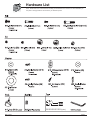
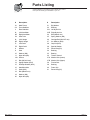
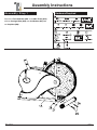
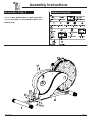
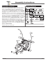
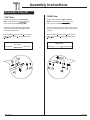
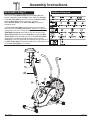
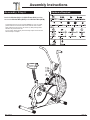
Fan Bike
BRF 700
BRF 701
* This item is for consumer use only and it is not meant for commercial use.
OW N E R ’ S M A N UA L
General Information
Safety
Before you undertake any exercise program,
please be sure to consult with your doctor.
Frequent strenuous exercise should be
approved by your doctor and proper use
of your product is essential. Please read
this manual carefully before commencing
the assembly of your product or starting to
exercise.
• Please keep all children away from this item
when in use. Do not allow children to climb or
play on them when they are not in use.
• Supervise teenagers while they use this unit.
• For your own safety, always ensure that there
is at least 3 feet of free space in all directions
around your product while you are exercising.
• Regularly check to see that all nuts, bolts and
fittings are securely tightened. Periodically
check all moving parts for obvious signs of
wear or damage.
• Clean only with a damp cloth, do not use
solvent cleaners. If you are in any doubt, do
not use your product; contact CUSTOMER
SUPPORT.
• Before use, always ensure that your product
is positioned on a solid, flat surface. If
necessary, use a rubber mat underneath to
reduce the possibility of slipping.
• Always wear appropriate clothing and
footwear such as training shoes when
exercising. Do not wear loose clothing that
could become caught in moving parts during
exercise.
• Do not use this unit if it is not functioning
properly or if it is not fully assembled.
• Do not use this unit for commercial purposes.
• Before use, you must read and understand all
instructions & warnings stated in this Owner’s
Manual as well as posted on the equipment.
• It is the facility owner’s responsibility to properly
instruct users on the proper operation of the
equipment and to warn them of the potential
hazards.
• If at any time during exercise you feel faint, dizzy
or experience pain, stop and consult your
physician.
Assembling Tools
- Ruler with both metric and English measurements
- 2 x Adjustable Wrenches
- 1 x Philips (”Crosshead”) Screw Driver
Weight Limit
Your product is suitable for users weighing:
250 pounds or less.
BRF 700/701
Storage and Use
Your product is intended for use in clean
dry conditions. You should avoid storage in
excessively cold or damp places as this may
lead to corrosion and other related problems.
Warranty
Body Flex Sports warrants your product for
a period of 1 year for the frame and 90 days
on all parts if the item is used for the intended
purpose, properly maintained and not used
commercially. Any alterations or incorrect
assembly of the product will void this warranty.
Proof of purchase must be presented for any
warranty validation (no exceptions). This
warranty applies to the original purchaser only
and is not transferable.
This warranty does not cover abuse or defects
caused during use, storage or assembly.
During the warranty period, Body Flex Sports
reserves the right to:
a). provide replacement parts to the
purchaser in an effort to repair the item.
b). repair the product returned to our
warehouse (at the purchaser’s cost).
c). replace the product if neither of the two
previously mentioned actions effect repair.
This warranty does not cover normal wear and
tear on upholstery.
Questions
If you have any questions concerning the
assembly of your item or if any parts are
missing, please DO NOT RETURN THE
ITEM TO THE STORE OR CONTACT THE
RETAILER. Our dedicated customer service
staff can help you with any questions you may
have regarding the assembly of this unit and
can also mail you replacement parts.
Customer Support
Customer Support is open 9:00 a.m. to 5:00
p.m. (Pacific Time) Monday through Friday.
Please contact us by any of the following
means.
Body Flex Sports, Inc.
21717 Ferrero Parkway, Walnut, CA 91789
Telephone: (888) 266 - 6789
Fax: (909) 598 - 6707
Email: info@bodyflexsports.com
Page 1
Hardware List
The following hardware is used to assemble your unit. Please take a moment to familiarize yourself with these
items. Please note some of this hardware is already pre-assembled on the machine. Do not be alarmed if you
see parts on this page that are not included in your hardware packet
S10-S13-S15-S17-S19 [1 piece]
BRF 700/701
Page 2
Parts Listing
The following parts list describes all of the parts illustrated on the
exploded diagram on the following page. Please note, most of
these parts are already pre-assembled on your unit.
#
Description
#
Description
1A
2A
3
Main Frame
Front Stabilizer
21
22
Big Washer
Bushing
Rear Stabilizer
23L
Left Nylon Nut
4L
Left Handlebar
23R Right Nylon Nut
4R
5A
Right Handlebar
24
Seat Tube
25
Bolt (M8x16 mm)
Spring Washer (M8)
6L
Left Linkage
26
Carriage Bolt (M10x57 mm)
6R
7L
Right Linkage
Left Pedal
27
28
Arc Washer (M10)
Cap Nut (M10)
7R
Right Pedal
29
Special Washer
8
9
Monitor
Seat
30
34
Round Cap (50)
Bushing
10
Washer (M8)
35
Bearing
Nylon Nut (M8)
12A Bellows
36
Tension Control
13
Bolt (M10x18 mm)
37B Monitor Wire (Upper)
14
Spring Washer (M10)
38
Friction Belt
15
16
D Shape Washer (M10)
Handlebar Axle
39
40
Bushing
Foam Grip
17
Knob (M12)
41
Round Cap (25)
18
19
Bolt (M8x43 mm)
Washer (M8)
20
Nylon Nut (M8)
11
BRF 700/701
BRM 3670 Stride Cycle
37A Monitor Wire (Lower)
Page 3
Page ?
Exploded Diagram
The following diagram is provided to help you familiarize yourself with the parts and
hardware that will be used during the assembly process. Please note that not all of the
parts and hardware you see here will be used while you are assembling the machine
because some of these items are already pre-installed. Please continue to the next
page to begin the assembly process and use this page only as a reference guide for
parts and hardware.
23R
BRF 700/701
Page 4
Assembly Instructions
Hardware Required
Assembly Step 1
2
Secure the Front Stabilizer (#2A)to the Main Frame (#1A)
with two Carriage Bolts (#26), two Arc Washers (#27) and
two Cap Nuts (#28).
2
2
55
40
1
2
3
55
40
1
BRF 700/701
2
3
4
Page 5
4
Assembly Instructions
Hardware Required
Assembly Step 2
4
Secure the Rear Stabilizer (#3) to the Main Frame (#1A)
with four Bolts (#24), four Spring Washers (#25) and four
Washers (#19).
4
4
55
40
1
2
3
55
40
1
BRF700/701
2
3
4
Page 6
4
Assembly Instructions
Hardware Required
A s s e m b l y S t e p 3-A
Attach the Right Pedal (#7R) to the Right Linkage (#6R)
using a Bushing (#22) and a Big Washer (#21) in between.
Then screw the Right Pedal (#7R) tightly into the right
crank and then secure it with the Right Nylon Nut (#23R)*.
Repeat this process on the left side**.
Please Note:
•
Left Hand Side: Turn COUNTERCLOCKWISE to tighten the
55
Left Pedal (#7L) on the left crank. Then turn CLOCKWISE to
tighten the Left Nylon Nut (#23L) [BLACK i nner nylon ring] to
secure the left pedal assembly.
•
40
1
Right Hand Side: Turn CLOCKWISE to tighten the Right Pedal
2
3
(#7R) on the right crank. Then turn COUNTERCLOCKWISE to
tighten the Right Nylon Nut (#23R) [WHITE inner nylon ring] to
55
secure the right pedal assembly.
40
1
2
3
4
Right Crank
BRF 700/701
Page 7
4
Assembly Instructions
A s s e m b l y S t e p 3-B
**LEFT Side:
*RIGHT Side:
FOR PROPER ASSEMBLY, please ensure that the Left Linkage
(#6L) is assembled to the outter edge (away from shroud) of the
Left Crank.
FOR PROPER ASSEMBLY, please ensure that the Right Linkage
(#6R) is assembled to the outter edge (away from shroud) of the
Right Crank.
The order of parts (from inner side to outter) should look like the
exploded diagram below in the following sequence:
The order of parts (from inner side to outter) should look like the
exploded diagram below in the following sequence:
Left Nylon Nut (#23L) > Left Crank > Left Linkage (#6L) >
Big Washer(#21) > Bushing (#22) > Left Pedal (#7L)
Right Nylon Nut (#23R) > Right Crank > Right Linkage (#6R) >
Big Washer(#21) > Bushing (#22) > Right Pedal (#7R) 55
40
1
3
*RIGHT Side:
**LEFT Side:
OUTTER (SIDE)
2
INNER (SIDE)
INNER (SIDE)
OUTTER (SIDE)
55
40
1
Left Crank
PLEASE NOTE:
LEFT SIDE: Please ensure that the notched side of Bushing (#22)
is facing Big Washer (#21) from the left side so that Bushing (#22)
can be inserted into Big Washer (#21) and the two pieces fit
flushed together. Please refer to the exploded diagram for correct
orientation and positioning.
22
BRF 700/701
21
2
3
4
Right Crank
PLEASE NOTE:
RIGHT SIDE: Please ensure that the notched side of Bushing (#22)
is facing Big Washer (#21) from the right side so that Bushing (#22)
can be inserted into Big Washer (#21) and the two pieces fit
flushed together. Please refer to the exploded diagram for correct
orientation and positioning.
21
22
Page 8
4
Assembly Instructions
Hardware Required
A s s e m b l y S t e p 4-A
Remove the two Special Washers (#29), two D Shape washers
(#15), two Spring Washers (#14) and two Bolts (#13) that are
pre-assembled on the Handlebar Axle (#16). Insert the Handlebar
Axle (#16) through the Main Frame (#1A). Make sure the Handlebar
Axle (#16) is centered. If you encounter too much friction, try using
WD40 or Vaseline as a lubricant. Insert two Special Washers (#29)
that were just removed on the Handlebar Axle (#16) followed by
Right Handlebar (#4R) and Left Handlebar (#4L) on each side and
55
then secure them with two D Shape washers (#15), two Spring
Washers (#14) and two Bolts (#13) that were just removed.
Carefully cut off the zip tie on the bushing of the Right Linkage (#6R)*
Then attach the Right Handlebar (#4R) to the Right Linkage (#6R) with a
40
1
2
3
Washer (#19) in the between, secure with a Bolt (#18), a Washer
(#19) and a Nylon Nut (#20).
55
Repeat this process on the left side**.
40
1
BRF 700/701
2
3
4
Page 9
4
Assembly Instructions
A s s e m b l y S t e p 4-B
**LEFT Side:
*RIGHT Side:
Please ensure that the Left Handlebar
Please ensure that the Right Handlebar
The order of parts (from inner side to outter)
should look like the exploded diagram below
in the following sequence:
The order of parts (from inner side to outter) should
look like the exploded diagram below in the following
sequence:
Nylon Nut (#20) > Washer (#19) > Left Linkage
(#6L) > Washer (#19) > Left Handlebar (#4L)
> Bolt (#18)
Nylon Nut (#20) > Washer (#19) > Right Linkage
(#6R) > Washer (#19) > Right Handlebar (#4R)
> Bolt (#18)
(#4L) is assembled to the outter edge (away
from shroud) of the Left Linkage (#6L).
(#4R) is assembled to the outter edge (away
from shroud) of the Right Linkage (#6R).
*RIGHT Side:
**LEFT Side:
OUTTER (SIDE)
BRF 700/701
INNER (SIDE)
INNER (SIDE)
OUTTER (SIDE)
Page 10
Assembly Instructions
Assembly Step 5
Hardware Required
Remove the three Washers (#10) and three Nuts (#11) that
are pre-assembled on the Seat (#9). Then, attach the Seat (#9)
to the Seat Tube (#5A) and secure it with three Washers (#10)
and three Nuts (#11) that were previously removed.
Attach Bellows (#12A) to the Seat Tube (#5A) as shown in
illustration below.
Insert the Seat Tube (#5A) into the opening of the post that is
protruding from the Main Frame (#1A) a minimum of 4 inches to
engage the lowest hole. Please ensure that the hole on the Seat
Tube (#5A) is facing the same side as the hole located on the
Main Frame (#1A) and insert the Knob (#17) through the Main
Frame (#1A) post and through the hole on the Seat Tube (#5A).
Please refer to the illustration below. Always ensure that the
Knob (#17) is securely tightened and engaged through the hole on
the Main Frame (#1A) and the hole setting most comfortable to you
on the Seat Tube (#5A) for your safety.
55
40
1
2
3
55
40
1
BRF 700/701
2
3
4
Page 11
4
Assembly Instructions
Hardware Required
Assembly Step 6
Attach the Monitor (#8) to the Main Frame (#1A) and then
connect the Monitor Wire (#37A) to the Monitor Wire (#37B).
The assembly process is now complete. However, for your own safety,
please make sure to read this entire Owner’s Manual which includes
safety instructions and warnings, as well as any safety/warning labels
affixed to the product before use.
For your safety, please visually and functionally inspect and test the unit
after assembly is complete.
55
40
1
2
3
55
40
1
BRF 700/701
2
3
4
Page 12
4
Assembly Instructions
Tension Adjustment
For slight tension adjustment, simply turn the tension adjustment knob found at the top center. Tension level can be
manipulated this way to vary intensity of workout as you exercise.
For greater tension adjustment, you may loosen or tighten the Friction Belt (#38) by re-strapping it. To do so, first
turn the tension adjustment knob all the way to the loosest setting. Then re-strap the belt at the buckle on the main
frame, just beneath the flat beam at the top center. The more length you allow for the friction belt to wrap around the
wheel, the less friction it will cause. Re-adjust the tension knob after you finished re-strapping.
55
40
1
2
3
55
40
1
BRF 700/701
2
3
4
Page 13
4
Safety & Maintenance
SAFETY & WARNINGS
• Make sure all nuts, bolts, and screws are tightened prior to use.
• Be sure that all adjustment locking devices and safety devices are properly engaged prior to use!
• Never over-tighten the above-mentioned devices and parts to avoid damage to the unit.
• Check for loose parts and components and make proper adjustments prior to use.
• Check to see if there are any tears or bends in the welding or metal prior to use. If tears or bends
are found, do NOT use the unit and contact our CUSTOMER SUPPORT.
• Extreme care must be taken to not allow your feet, fingers, hair, clothing, and/or any loose items to be
snagged into any portion of the bike when the unit is in motion. Failure to follow these instructions
could result in serious injury, including the loss of fingers.
• Always wait for the pedals and other moving parts (which can gain great momentum during riding) to
come to a complete stop before dismounting the unit to avoid serious injury.
Maintenance & Care
• Please review all safety instructions and warnings in this entire Owner’s Manual, as well as any
safety/warning labels affixed to the product before use.
• Do not use solvent cleaners. If you are in any doubt, do not use your cleansing product;
contact CUSTOMER SUPPORT.
• The specific Parts on your unit which may see possible signs of wear after prolonged use are listed as
follows (please check these parts before each use):
Tension Control (#36); Left/Right Pedals (#7L/#7R); Left/Right Handlebars (#4L/#4R)
• For any replacement warning labels, please contact our CUSTOMER SUPPORT at (888) 266-6789
or (909) 598-9876, or mail in a written request to: Body Flex Sports, Inc. 21717 Ferrero Parkway,
Walnut, CA 91789. More detailed information about how to reach our CUSTOMER SUPPORT may
be found on Page 1 of the Owner’s Manual under the “CUSTOMER SUPPORT” section.
BRF 700/701
Page 14
Computer Operation
SPECIFICATIONS:
TIME………………………………………0:00-99:59
SPEED……………………………………0.0-99ML/H
DISTANCE ……………………………0.0-999.9ML
CALORIES………………………………0.0-9999CAL
KEY FUNCTION:
MODE: This key lets you to select and lock on to a particular function you want.
OPERATION PROCEDURES:
1. AUTO ON/OFF:
◆ The system turns on when any key is depressed of when it receives an input from the speed
sensor.
◆ The system turns off automatically when the speed sensor has no signal input or no key are pressed for
approximately 4 minutes.
2. RESET:
The unit can be reset by changing battery or pressing the MODE key for 3 seconds.
3. FUNCTION:
Top portion of LCD Display
o
Speed: Display the current speed
Lower portion of the LCD Display (Press Mode to alternate through the following functions)
o
Time: Display the total amount of time using the machine.
o
Distance : Display the distance travelled.
o
Calories : Display the amount of calories burned.
o
Scan : Automatically alternate between the different functions. (Time, Distance, Calories)
4.BATTERY:
This monitor requires one (or two) "AA" Battery(ies).
You can replace the battery from the back of the unit.
Please note: The computer is not intended for use as a medical device. Various factors may
affect the accuracy of the function/mode readings, and may vary from other measurement
calculations from other devices. The computer is intended only as an exercise aid to track
relative progress when using the corresponding exercise unit.
BRF 700/701
Page 15
PLEASE KEEP THESE INSTRUCTIONS FOR FUTURE USE & REFERENCE.
DO NOT DISCARD.
WARNING: SERIOUS INJURIES AND EVEN DEATH CAN OCCUR IF THE PROPER SAFETY PRECAUTIONS ARE NOT FOLLOWED.
The diagram below highlights and reviews many of the important Safety and Warning labels also found
on the unit. Please ensure any user of the unit familiarizes themselves with these Safety and Warning
guidelines before use.
!
WARNING!
The use of this exercise equipment involves a RISK OF PHYSICAL INJURY as well as
property damage, which can be minimized by observing the following guidelines:
1. ALWAYS wear comfortable clothing
and shoes with good traction.
2. ALWAYS make sure all nuts and bolts
are secured before use. TIGHTEN
PEDAL HINGE BOLTS EVERY 30
DAYS.
3. STOP EXERCISING if you become
dizzy, nauseous, have irregular
heartbeats or breathing difficulties.
Contact your physician immediately.
4. ALWAYS keep a large mat under the
Equipment to protect the floor or carpet.
5. ALWAYS use your Equipment in a
warm, dry, level well-lit and ventilated
indoor area.
7. ALWAYS keep your Equipment clean
and free of dust, moisture, debris and
loose objects.
8. NEVER use the Equipment if you are
injured or have a physical condition
that impairs your balance. DO NOT
exercise under the influence of
medication or alcohol.
9. NEVER allow small children or pets to
approach the Equipment. It is not a
toy.
10. NEVER use the Equipment if you
exceed its weight limit of 250 lbs.
11. NEVER use the Equipment if it does
not function properly.
6. ALWAYS keep body and clothing free
and clear of all moving parts.
BRF 700/701
Page 16
This page intentionally left blank
Proof of purchase
Model Number BRF700/701
version: 05-1-2013
BRF 700/701
Body Flex Sports, Inc. • 21717 Ferrero Parkway, Walnut, CA 91789 • Telephone: (888) 266 - 6789 • Email: [email protected]