1
apanlZ®
Model 5M-11 51 User Guide
Stereo Power Amplifier
RISK OF ELECTRIC SHOCK
DO NOT OPEN
CAUTION: TO REDUCE THE RISK OF ELECTRIC SHOCK,
DO NOT REMOVE COVER (OR BACK)
NO USER-SERVICEABLE PARTS INSIDE
REFER SERVICING TO QUALIFIED SERVICE PERSONNEL
The lightning flash with arrowhead symbol within
an equilateral triangle is intended to alert the
user to the presence of uninsulated "dangerous
voltage" within the product's enclosure that may
be of sufficient magnitude to constitute a risk of
electric shock to persons.
The exclamation point within an equilateral
triangle is intended to alert the user to
the presence of important operating and
maintenance (servicing) instructions in the
literature accompanying the product.
WARNING
TO REDUCE THE RISK OF FIRE OR ELECTRIC SHOCK, DO NOT EXPOSE THIS APPLIANCE
TO RAIN OR MOISTURE.
CAUTION: TO PREVENT ELECTRIC SHOCK, MATCH WIDE BLADE OF PLUG TO WIDE
SLOT, FULLY INSERT.
ATTENTION: POUR EVITER LES CHOCS ELECTRIQUES, INTRODUIRE LA LAME LA
PLUS LARGE DE LA FICHE DANS LA BORNE CORRESPON·DANTE DE LA PRISE ET
POUSSER JUSQU'AU FOND.
IMPORTANT SAFETY
INSTRUCTIONS
READ BEFORE OPERATING EQUIPMENT
This product was designed and manufactured to meet strict quality and safety standards.
There are, however, some installation and operation precautions which you should be particularly aware of.
1.
Read these instructions.
2.
Keep these instructions.
3.
Heed all warnings.
4.
Follow all instructions.
5.
Do not use this apparatus near water.
6.
Clean only with dry cloth.
7.
Do not block any ventilation openings. Install in accordance with the manufacture's instructions.
8.
Do not install near any heat sources such as radiators, heat registers, stoves, or other apparatus (including amplifiers) that
produce heat.
9.
Do not defeat the safety purpose of the polarized or grounding-type plug. A polarized plug has two blades with one wider than
the other. A grounding type plug has two blades and a third grounding prong. The wide blade or the third prong are provided for
your safety. If the provided plug does not fit into your outlet, consult an electrician for replacement of the obsolete outlet.
10. Protect the power cord from being walked on or pinched particularly at plugs, convenience receptacles, and the point where they
exit from the apparatus.
11. Only use attachments/accessories specified by the manufacturer.
12. Use only with the cart, stand, tripod, bracket, or table specified by the manufacturer, or sold with the apparatus. When a cart is
used, use caution when moving the carVapparatus combination to avoid injury from tip-over.
13. Unplug this apparatus during lightning storms or when unused for long periods of time.
14. Refer all servicing to qualified service personnel. Servicing is required when the apparatus has been damaged in any way, such
as power-supply cord or plug is damaged, liquid has been spilled or objects have fallen into the apparatus, the apparatus has
been exposed to rain or moisture, does not operate normally, or has been dropped.
Additional Safety Information!
• This product should not be placed in a built-in installation such as a bookcase or rack unless proper ventilation is provided or the
manufacturer's instructions have been adhered to.
• Apparatus shall not be exposed to dripping or splashing and that no objects filled with liquids, such as vases, shall be placed on
the apparatus.
• When the switch is in the OFF position, the apparatus isn't completely switched-off from the MAINS.
• The equipment shall be installed near the Socket-Outlet and shall be easily accessible.
Do not touch hot spots during and immediately after use.
During and immediately after use, this product is hot in areas other than the controls and rear panel connection jacks. Do not touch
hot spots and especially the top panel. Contact with hot areas can cause burns.
Do not expose the unit to excessive heat such as direct sunlight, fire or the like.
IAMP
070719U2!
WARRANTY
For warranty information, contact your local Marantz distributor.
RETAIN YOUR PURCHASE RECEIPT
Your purchase receipt is your permanent record of a valuable purchase.
It should be kept in a safe place to be referred to as necessary for
insurance purposes or when corresponding with Marantz.
IMPORTANT
When seeking warranty service, it is the responsibility of the consumer to
establish proof and date of purchase. Your purchase receipt or invoice is
adequate for such proof.
FOR U.K. ONLY
This undertaking is in addition to a consumer's statutory rights and
does not affect those rights in any way.
GARANTIE
Voor inlichtingen omtrent garantie dient u zich tot uw plaatselijke
Marantz.
UW KWITANTIE, KASSABON E.D. BEWAREN
Uw kwitantie, kassabon e.d. vormen uw bewijs van aankoop van
een waardevol artikel en dienen op een veilige plaats bewaard te
worden voor evt, verwijzing bijv, in verbend met verzekering of bij
correspondentie met Marantz.
BELANGRIJK
Bij een evt, beroep op de garantie is het de verantwoordelijkheid van de
consument een gedateerd bewijs van aankoop te tonen. Uw kassabon
of factuurzijn voldoende bewijs.
ITALIANo
GARANTIE
Pour des informations sur la garantie, contacter Ie distributeur local
Marantz.
CONSERVER L 'ATTESTATION D'ACHAT
L'attestation d'achat est la preuve permanente d'un achat de valeur.
La conserver en lieu sur pour s'y reporter aux fins d'obtention d'une
couverture d'assurance ou dans Ie cadre de correspondances avec
Marantz.
IMPORTANT
Pour I'obtention d'un service couvert par la garantie, il incombe au
client d'etablir la preuve de I'achat et d'en corroborer la date. Le rec;:u
ou la facture constituent des preuves suffisantes.
GARANTIE
Bei Garantiefragen wenden Sie sich bitte an Ihren Marantz-Handler.
HEBEN S/E IHRE QUITTING GUT AUF
Die Ouittung dient Ihnen als bleibende Unterlage fOr Ihren wertvollen
Einkauf Das Aufbewahren der Ouittung ist wichtig, da die darin
enthaltenen Angaben fOr Versicherungswecke oder bei Korrespondenz
mit Marantz angefOhrt werden mOssen.
WICHTIGI
Bei Garantiefragen mu B der Kunde eine Kaufunterlage mit
Kaufdatum vorlegen. Ihren Ouittung oder Rechnung ist als Unterlage
ausreichend.
GARANZIA
L:apparecchio coperto da una garanzia di buon funzionamento della
durata di un anno, 0 del periodo previsto dalla legge, a partire dalla
data di acquisto comprovata da un documento attestante il nominativo
del Rivenditore e la data di vendita. La garanzia sara prestata con la
sostituzione 0 la riparazione gratuita delle parti difettose.
Non sono coperti da garanzia difetti derivanti da uso improprio, errata
installazione, manutenzione effettuata da personale non autorizzato
0, comunque, da circostanze che non possano riferirsi a difetti di
funzionamento dell'apparecchio. Sono inoltre esclusi dalla garanzia
gli interventi inerenti I'installazione e I'allacciamento agli impianti di
alimentazione.
Gli apparecchi verranno riparati presso i nostri Centri di Assistenza
Autorizzati. Le spese ed i rischi di trasporto sono a carico del cliente.
La casa costruttrice declina ogni responsabilita per danni diretti 0 indiretti
provocati dalla inosservanza delle prescrizioni di installazione, uso e
manutenzione dettagliate nel presente manuale 0 per guasti dovuti ad uso
continuato a fini professionali.
e
CE MARKING
(E:
(E:
(E:
(E:
(E:
Franfais
AVERTISSEMENTS
English
The SM-11 S1 is in conformity with the EMC directive and
low-voltage directive.
-
Fran~ais
Le SM-11 S1 est conforme 11 la directive EMC et 11 la directive
sur les basses tensions.
Deutsch
Das Modell SM-11 Sl entspricht den EMC-Richtlinien und
den Richtlinien fOr Niederspannungsgerate.
-
Nederlands
De SM-11 S1 voldoet aan de EMC eisen en de vereisten
voor laag-voltage.
Italiano
II SM-11 S1 e conforme aile direttive CEE ed a quelle per i
bassi voltaggi.
-
English
WARNINGS
-
-
Do not expose the equipment to rain, moisture, dripping or
splashing.
Do not remove the cover from the equipment.
Do not insert anything into the equipment through the ventilation
holes.
Do not handle the mains cord with wet hands.
Do not cover the ventilation with any items such as tablecloths,
newspapers, curtains, etc.
No naked flame sources, such as lighted candles, should be placed
on the equipment.
When disposing of used batteries, please comply with governmental
regulations or environmental public instruction's rules that apply in
your country or area.
Make a space of about 0.2 meter around the unit.
No objects filled with liquids, such as vases, shall be placed on the
equipment.
When the switch is in the OFF position, the equipment is not
completely switched 011 from MAINS.
The equipment shall be installed near the power supply so that the
power supply is easily accessible.
- Do not touch hot spots during and immediately after use.
During and immediately after use, this product is hot in areas other
than the controls and rear panel connection jacks. Do not touch hot
spots and especially the top panel. Contact with hot areas can cause
burns.
Do not expose the unit to excessive heat such as direct sunlight, fire
or the like.
-
Ne pas exposer I'appareil 11 la pluie, 11 I'humidite, 11 I'egouttement ou
aux eclaboussures.
Ne pas essayer de retirer Ie boltier de I'appareil.
Ne rien inserer dans I'appareil par les orifices de ventilation.
Ne pas manipuler Ie cordon d'alimentation avec les mains
mouillees.
Ne pas recouvrir les oures de ventilation avec un objet quelconque
comme une nappe, un journal, un rideau, etc.
Ne placer aucune source de flamme nue, comme une bougie
allumee, sur I'appareil.
Pour mettre au rebut les piles usees, respecter les lois
gouvernementales ou les reglements officiels concernant
I'environnement qui s'appliquent 11 votre pays ou region.
Veiller 11 ce qu'aucun objet ne soit 11 moins de 0,2 metre des cotes
de I'appareil.
Aucun objet rempli de Iiquide, un vase par exemple, ne doit etre
place sur I'appareil.
Lorsque I'interrupteur est sur la position OFF, I'appareil n'est pas
completement deconnecte du SECTEUR (MAINS).
L'appareil sera installe pres de la source d'alimentation, de sorte que
cette derniere soit facilement accessible.
Ne pas toucher aux zones chaudes pendant et immectiatement
apres I'utilisation.
Pendant I'utilisation et immediatement apres, cet appareil est chaud
en dehors des commandes et des prises de raccordement arriere.
Ne pas toucher aux zones chaudes, et particulierement au panneau
superieur, pour eviter tout risque de brOlure.
Ne pas exposer I'appareil 11 une chaleur excessive, comme celie des
rayons directs du soleil, d'un feu, etc.
Deutsch
WARNHINWEISE
- Das Gerat nicht Regen, Feuchtigkeit, Tropf- oder Spritzwasser
aussetzen.
Die Abdeckung nicht vom Gerat abnehmen.
Keine Gegenstande durch die BelOftungsschlitze stecken.
- Das Netzkabel nicht mit feuchten oder nassen Handen anfassen.
Decken Sie die LOftungs611nungen nicht mit einem Tischtuch, einer
Zeitung, einem Vorhang usw. abo
Es dOrfen keine Gegenstande mit offener Flamme, wie etwa
brennende Kerzen, auf dem Gerat aufgestellt werden.
Beachten Sie bei der Entsorgung der verbrauchten Batterien aile
geltenden lokalen und Oberregionalen Regelungen.
Auf allen Gerateseiten muB ein Zwischenraum von ungefahr 0,2
meter vorhanden sein.
- Auf das Gerat dOrfen keine mit FIOssigkeiten gefOlite Behalter, wie
etwa eine Vase, gestellt werden.
Wenn der Schalter ausgeschaltet ist (OFF-Position), ist das Gerat
nicht vollstandig vom Stromnetz (MAINS) abgetrennt.
Das Gerat sollte in der Nahe einer Netzsteckdose aufgestellt
werden, damit es leicht an das Stromnetz angeschlossen werden
kann.
- BerOhren Sie wahrend oder unmittelbar nach dem Gebrauch keine
heiBen Stellen des Gerates.
Wah rend oder unmittelbar nach dem Gebrauch ist dieses Produkt
mit Ausnahme der Bedienelemente und der Anschlussbuchsen
auf der ROckseite heiB. BerOhren Sie die heiBen Stellen und
insbesondere die Oberseite nicht. Der Kontakt mit heiBen Flachen
kann zu Verbrennungen fOhren.
Setzen Sie das Gerat keiner ObermaBigen Warme aus, z.B. durch
Aufstellung in direkter Sonneneinstrahlung, in der Nahe eines
ollenen Feuers usw.
Nederlands
WAARSCHUWINGEN
- Stel het apparaat niet bloot aan regen, vocht, druppels of spetters.
- Verwijder de afdekplaat van het apparaat niet.
Duw niets door de ventilatieopeningen in het apparaat.
Raak het netsnoer niet met natte handen aan.
Bedek de ventilatieopeningen niet met enige voorwerpen, zoals
tafelkleden, kranten, gordijnen, enz.
Plaats geen brandende voorwerpen, zoals kaarsen, op het
apparaat.
Voig bij hetweggooien vanverbruiktebatterijen de overheidswetgeving
of milieuvoorschriften op die van kracht zijn in het land of de regio
waarin u zich bevindt.
- Zorg dat er 0,2 meter vrije ruimte rond het toestel is.
Plaats geen voorwerpen met een vloeistof erin, zoals een
bloemenvaas, op het apparaat.
Ais de schakelaar op OFF staat, is het apparaat niet volledig
losgekoppeld van de netspanning (MAINS).
De apparatuur wordt in de buurt van het stopcontact ge'installeerd,
zodat dit altijd gemakkelijk toegankelijk is.
Raak hete gedeelten van het apparaat niet aan tijdens en
onmiddellijk na het gebruik.
Tijdens en onmiddellijk na het gebruik is dit product heet, behalve
in de omgeving van de bedieningstoetsen en de aansluitingen
op het achterpaneel. Raak geen hete plekken aan, vooral niet
het bovenpaneel. Contact met hete plekken kan brandwonden
veroorzaken.
- Stel het apparaat niet bloot aan grote warmte, zoals direct zonlicht,
vuur en dergelijke.
Italiano
AVVERTENZE
- Non esporre I'apparecchio alia pioggia, all'umidita, al gocciolamento
o agli spruzzi.
Non rimuovere il coperchio dell'apparecchio.
Non introdurre oggetti all'interno dell'apparecchio attraverso i fori di
ventilazione.
Non toccare il cavo di alimentazione con Ie mani bagnate.
Non coprire Ie fessure di ventilazione con tovaglie, giornali, tende od
oggetti analoghi.
- Non posare sull'apparecchio sorgenti di fiamme scoperte quali
candele accese.
- Smaltire Ie pile usate in conform ita aile norme governative 0
disposizioni ambientali vigenti nel proprio paese 0 zona.
- Lasciare 0,2 metro liberi tutto intorno I'unita.
Non mettere sull'apparecchiatura alcun contenitore di liquido, come
ad esempio dei vasi.
- Quando I'interruttore nella posizione OFF, I'apparecchiatura non
completamente scollegata da MAINS.
- L.:apparecchio va installato in prossimita della fonte di alimentazione,
in modo che quest'ultima sia facilmente accessibile.
e
e
Non toccare i punti caldi ne durante, ne immediatamente dopo
I'uso.
Durante, e subito dopo I'utilizzo, questa prodotto risulta essere molto
caldo in alcune sue parti come ad esempio i connettori del pannello
posteriore. Non toccare i punti caldi e specialmente la superficie del
pannello. II contatto con parti calde puo provocare ustioni.
Non esporre I'unita ad eccessivo calore come la luce diretta del sole,
il fuoco 0 simili.
IAMP 070719N1 I
Thank you for purchasing this Marantz SM-11S1 Stereo Power Amplifier.
Please read these operating instructions carefully. We recommend that you read the entire user guide before
you attempt to connect or operate the player.
After you have reviewed the contents of this manual, we suggest that you make all system connections before
you attempt to operate the unit.
• Checking the accessories
A NOTE ABOUT RECYCLING
After opening the cover of the packing box, check that the
following accessories are included.
• AC Power cord
SM-11 S1 (U.S.A.)
SM-11S1 (Europe)
• User Guide
This product's packaging materials are recyclable
and can be reused. This product and the accessories
packed together are the applicable product to the WEEE
directive except batteries.
Please dispose of any materials in accordance with your
local recycling regulations.
When discarding the unit, comply with your local rules
or regulations.
Batteries should never be thrown away or incinerated
but disposed of in accordance with your local regulations
concerning chemical wastes.
• Warranty Card (U.S.A)
(U.S.A. x 1, Canada x 1)
[~C_O_N_TE_N_T_S
~]
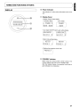
FEATURES
2
BEFORE USING
3
EQUIPMENT MAINS WORKING SETIING
3
COPYRIGHT
3
INAPPROPRIATE PLACES FOR INSTALLATION
3
NAMES AND FUNCTIONS OF PARTS
4
FRONT PANEL
4
DiSPLAy
5
REAR PANEL
6
CONNECTIONS
7
BALANCED JACKS
WIRING SPEAKER CABLE
7
8
SPEAKER POSITIONING FOR SUPER AUDIO MULTI-CHANNEL SOUND
17
CONNECTING THE POWER SUPPLY
17
HOW TO USE AND SET FEATURES
18
HOW TO USE THE METER MODE BUTION (DIGITAL POWER METER)
18
BALANCED INPUT/UNBALANCED INPUT GAIN SETIINGS
18
AMP MODE
19
HOW TO OPERATE THE SIDE ILLUMINATION
19
REMOTE POWER CONTROL
20
TROUBLESHOOTING
21
SPECIFICATIONS & DIMENSIONAL DRAWiNGS
22
OTHERS
23
I
I
[~F_E_AT_U_R_ES
~]
lDa..anlZ
(5
....":"" ...
(;)
oPo,;".'"
0
-
Q
0
~,
<:>
.....;.::".0
e
0)
'\.
/
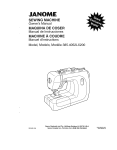
This unit was developed with many of the same functions as
the flagship model MA-9S2 and with a 2-channel function,
without compromising the sound quality.
•
HDAM-SA3
The HDAM-SA3 is an amp module equipped with a new circuit
that has further improved stability from the previous HDAM-SA
and HDAM-SA2.
The HDAM-SA3 is an essential part of this unit's amp module,
incorporated into many components such as the voltagecurrent converter and input buffer.
•
Dual Structure Voltage Amplifier
+ Power Buffer Amplifier
'\.
/
• Improved Instantaneous Current Delivery
Capacity
The final stage of the power buffer amp has a LAPT special
power transistor parallel push-pull construction to improve
delivery, and the block capacitor and power buffer amplifier
are unified.
Also, the block capacitor and unified power buffer enable the
reduction of the current loop path, creating superior channel
separation.
• Input Buffer
Each input has its own input buffer that directly uses HDAMSA3 technology to prevent interference between channels or
input sources.
Speakers with powerful magnetic circuits have large back
electromotive force, and are therefore not easy to drive.
Therefore, in the same way as the MA-9S2, this unit was
developed with the dual structure of a voltage amplifier and
power buffer amplifier so that there is no influence from the
back electromagnetic force.
The gain can be set individually for BALANCED input and
UNBALANCED input according to the intended use.
•
•
Differential Input Voltage Amplifier
The current feedback voltage amplifier that is equipped with
the newly developed HDAM-SA3 and features differential
input amplifies the voltage of the balanced input signals and
unbalanced input signals.
Furthermore, it can also be switched between gain conversion
or stereo mode to BTL monaural mode.
• BALANCED/UNBALANCED Individual Gain
Setting Function
The actual output power can be indicated on the display by
detecting the speaker output voltage and output current.
Considering overall sound quality, a PLD (programmable logic
device) is used instead of DSP for the digital processing to
minimize the amount of digital noise.
•
• New Current Feedback Power Buffer Amplifier
The power buffer amplifier that powerfully drives the speakers
incorporates a voltage-current conversion circuit that contains
a newly developed Complimentary Cascade Push-pull Circuit,
which greatly increases stability.
Furthermore, the combination of the Wilson current mirror
circuit and Cascade bootstrap circuit in the current amplification
circuit provides power amplification with low distortion in the
super-high frequency.
2
Digital Power Meter
Remote Power Control
The Power to this unit can be switched ON/OFF in sync with
the Marantz SC-11 S1 stereo control amplifier ON/OFF control
using the remote power control function.
The connection with the SC-11 S1 is made without a ground
loop being formed, therefore sound quality is not adversely
affected.
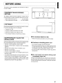
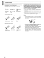
~-h-;sB-s-e~-ti-oF-n~-us-t-~-e-~-a-dU-b-e~-or-el_~-nY-~-o-n-ne-c-tio-n-i-S-m-ad-e-t-o-------------------~}
the mains supply.
0.2 m (8 ins.) or more
';=:L==""F=;===::!::::=====r""F==~0~.2 m (8 ins.)
EQUIPMENT MAINS WORKING
[~S_E_TT_IN_G
]
~
Your Marantz product has been prepared to comply with the
household power and safety requirements that exist in your area.
-
Power requirements (U.S.A.)
Power requirements (Europe)
or more
o
'0
'0
AC 120V 60Hz
AC 230V SO/60Hz
0.2 m (8 ins.) or more
( COPYRIGHT
)
Recording and playback of any material may require consent.
For further information refer to the following:
Copyright Act 1956
-
Dramatic and Musical Performers Act 1958
-
Performers Protection Acts 1963 and 1972
-
Any subsequent statutory enactments and orders
• Do not place objects on top
INAPPROPRIATE PLACES FOR
INSTALLATION
To keep your player in perfect working orderfor the longest possible
time, avoid installing the player in the following locations.
• Refrain from placing any objects on top of the player.
• Cautions on handling power cord
Wherever it will be exposed to direct sunlight
• Do not touch the power cord with wet hands.
Wherever it will be close to a heater or other heat-radiating
appliance
Wherever the humidity is high or ventilation is poor
• When disconnecting the power cord, always make sure that
you take hold of the plug. Yanking out or bending the cord
can damage it and/or cause electric shocks or a fire.
Wherever it is very dusty
Wherever it will be subject to vibration
• Get into the habit of disconnecting the power plug before
leaving home.
On top of a rickety stand or in an unstable location which is
tilted at an angle
In an audio rack with little space at the top and bottom or other
location where the heat dissipation will be obstructed
To ensure proper heat dissipation, install the player while
leaving clearances between the player and wall or other
components, as shown in the figure below.
• Do not touch hot spots during and
Immediately After Use
During and immediately after use, the unit is hot in areas other
than the controls and rear panel connection jacks. Do not touch
hot spots and especially the top panel. Contact with hot areas
can cause burns.
3
I
[
I
]
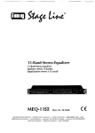
NAMES AND FUNCTIONS OF PARTS
( FRONT PANEL
)
~
Dllarantz
"£6:
0 ,.....
I"",,·,
,....-~
s ..."f....
(,))
'"
CD
Ii"
-= ~
7 8
9
Q
I
POWER ON/OFF Switch
®
This switch turns power to the SM-11 S1 ON and OFF.
When pressed, power is activated and the blue indicator
in the display C1J lights up. Pressing the switch again turns
the power OFF.
CV
Display
®
@ Balanced Input Selection Button
This button switches the input signal from the BALANCED
terminal on the rear panel ON/OFF.
Press this button for 3 seconds or more to set the gain
settings for the input signal from the BALANCED terminal.
For instructions on BALANCED INPUT I UNBALANCED
INPUT GAIN SETTING, see pg. 18.
4
~-..,
-~"
(;)
'\
~
2
/
3 4 5
METER MODE Button
Illumination Lamp
The illumination lamp casts a blue light over the switches
and buttons.
It can be turned ON and OFF with the DISPLAY button.
For instructions on HOW TO OPERATE THE SIDE
ILLUMINATION, see pg. 19.
UNBALANCED Input Selection Button
This button switches the input signal from the
UNBALANCED terminal on the rear panel ON/OFF.
Press this button for 3 seconds or more to set the gain
settings for the input signal from the UNBALANCED
terminal. For instructions on BALANCED INPUT I
UNBALANCED INPUT GAIN SETTING, see pg. 18.
·~.. I
This button changes the display to digital power meter
display mode. For more information on HOW TO USE
THE METER BUTTON (DIGITAL POWER METER), see
pg.18.
The monitor displays the output power to the speakers,
and setting status of the various setting modes.
®
'--
0
(J) DISPLAY Button
This button turns the display and side illumination ON and
OFF. For instructions on HOW TO OPERATE THE SIDE
ILLUMINATION, see pg. 19.
®
SPEAKERS 1 Button
This button switches the speaker output signal from the
SPEAKERS 1 terminal on the rear panel ON/OFF.
®
SPEAKERS 2 Button
This button switches the speaker output signal from the
SPEAKERS 2 terminal on the rear panel ON/OFF.
[~_N_A_M_E_S_A_N_D_F_UN_C_T_I_O_N_S_O_F_P._'A_R_T_S
( DISPLAY
------------~]
)
@ Power Indicator
This indicator is lit a blue color while power to the unit is
ON.
Q]) Display Panel
• Speaker Output Power Display
In STEREO Mode
In BTL Mode
• Input signal ON/OFF switch, gain setting display
ur'~ E: 1=1 LH['1 CE
E: HLHr-K: E[:1
• Meter mode setting display
r---;-:-=-=-=~---,
METER
METER
.;
,")
1
"
• Display when protective circuit trips
PF.:DTl::.CT
@ STANDBY Indicator
When using the remote power control function, this
indicator flashes when the unit is in standby mode.
Also, this indicator flashes if a protective circuit trips to
give notification of a malfunction.
5
I
[
I
]
NAMES AND FUNCTIONS OF PARTS
(REAR PANEL
~F=:::::;;;::::::::::::::==~======:::::::;@;;::=================:I~~~
='=
@
r=STEREO
Iron
!YO
SYSTEM 1 OR SYSTEM 2 ; 4 - 8 OHMS
SYSTEM 1 AND SYSTEM 2 : 8·16 OHMS
BTL; 8 OHMS
BTL: 16 OHMS
@
rnaranlZ
MODEL NO. SM·1151
@
@
@
tJ
tJ
@
@
@
@
lIl'mIlD'lIiI·rmm·B'!l.!!!~
@
TRIGGER IN r:: ON
FF
@
@ mO @
@
@
\~~,7
A
B
@ UNBALANCED INPUT Jack
These jacks are for connecting to the unbalanced output
jacks of a control amplifier. In BTL mode, the Lch input
terminal is used.
@ BALANCED INPUT Jacks
These jacks are for connecting to the balanced output
jacks of a control amplifier. In BTL mode, the Lch input
terminal is used.
~ REMOTE POWER CONTROL ON/OFF
Switch
ON:
Set to control this unit's power ON/OFF in sync with
the Marantz SC-11 S1 control amplifier ON/OFF
control.
OFF: Set to use the POWER ON/OFF switch on the
front panel of the unit to switch the unit's power
ON/OFF.
® AC IN Power Cable Connection Socket
© SPEAKER SYSTEMS Output Terminals
These jacks are for connecting to a speaker system.
You can connect 2 speaker systems to the SM-11 S1,
SPEAKER SYSTEM 1 and 2. Speaker output can be
turned ON/OFF from the SPEAKERS 1 / 2 buttons on
the front panel.
When using BLT mode, connect the speaker + side to the
Lch + jack, and the speaker - side to the Rch + jack.
© REMOTE POWER CONTROL Jacks
(TRIGGER IN)
This jack controls this unit's power ON/OFF in sync with
the Marantz SC-11 S1 control amplifier ON/OFF control.
Connect to the SC-11 S1 TRIGGER OUT jack using a
commercially available cable.
For more information on REMOTE POWER CONTROL,
see pg. 20.
6
Connect this socket to the power outlet using the included
power cable.
@ AMP MODE Switch
STEREO: Set to use the SC-11 S1 as an ordinary stereo
power amplifier.
BTL:
Set to connect a stereo amp by BTL and use
this unit as a monaural power amp.
For more information on AMP MODE, see pg. 19.
Caution:
Always make sure that the power is OFF before
switching this switch.
~ o-nC:ne~ :io~nN~ex:" aNm~p:" :I~=S:" :~=-_5- ':~ ,:=-~ =xa- ~ p-,eS- =-s
O-f-co-n-ne-ct-in-gt- h-is-un-it--(-B-A-L-A-N-C-E-O-J-A-C-K-S--------:
to a Marantz SC-11 S1 stereo control amplifier.
Refer to these connection examples when connecting to control
amplifiers other than the SC-11 S1.
Caution:
G) The BALANCED jacks on this unit are equipped with XLR
connectors that are widely used on professional equipment.
Their features are listed below.
• The 3 pin construction enables the musical signal to be
transmitted as a balanced signal, with little effect from
external noise
• Do not connect the power cord of this amplifier or any of
the other components to the power supply until all of the
connections are completed.
• The detachable locking mechanism minimizes connector
play and enhances connection reliability.
• Insert the plugs of the connections cords firmly into the
connecting jacks. Incorrect insertion may cause noise.
Connect the wires correctly to the L (left) and R (right)
channels. The red jack is the R (right) channel, and the
white jack is the L (left) channel.
• Make sure that input and output are connected correctly.
Refer also to the instruction manuals of components to
connect equipment correctly.
CD
The XLR connector for professional use is internally wired
in either of the following two systems.
1. USA system (Pin
CD = COLD, Pin @ = HOT)
COL~,L...)_'
_-'----"--'
2. European system (Pin
CD = HOT,
Pin @
= COLD)
@ This unit uses the 1. USA system.
When a preamp or main amplifier adopting the European
system is connected using a cable with XLR balanced
connectors, the reproduced signal may be inverted of
phase.
In this case, refer to "ANALOG OUTPUT CONNECTOR
PHASE SWITCHING", and set so that the correct phase
is used.
7
I
[
I
]
CONNECTIONS
( WIRING SPEAKER CABLE
• Peel off the coating of speaker cable as shown below.
Approx.1 em
1-------+1
(obdb=
(6;;;
Cut the coating
of cable.
Peel off the edge
of cable.
~
Your speaker system needs to meet the following requirements.
If speakers that do not meet the following requirements are
used, the amplifier protective circuit may trip, and sounds will
not playback correctly. In certain cases, damage may also be
caused to the amplifier and speaker system.
<J:jssssss~
• If using 1 set of speakers, total speaker impedance must be
4Q or more.
Twist conductors.
• If using 2 sets of speakers, total speaker impedance must
be 8Q or more.
• When using the speaker system in BTL mode, use a speaker
system that has an impedance of 8Q or higher.
• Wiring with speaker cable.
Notes:
• To prevent damage to circuitry, do not let the bare speaker
wires touch each other and do not let them touch any metal
part of this unit.
Turn counterclockwise to loosen.
Insert conductor
of cable.
Turn clockwise to
tighten.
• Wiring with "Y" style terminal
• Do not touch the speaker terminals when the power is on.
It may cause you to receive an electric shocks.
• Do not connect more than one speaker cable to one
speaker terminal. Doing so may damage this unit.
Turn counterclockwise to loosen.
s
Insert conductor.
Turn clockwise to
tighten.
Be sure to connect the positive and negative cables for
the speaker properly. If they are miss-connected, the
signal phase will be reversed and the signal quality will
be corrupted.
J
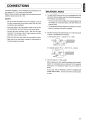
[__C_O_N_N_E_C_T_IO_N_S
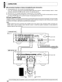
• Connection Example1 : Basic Connection for Normal Stereo Playback
CD Player
II
II
,@
@
To LINE OUT jack
Control Amplifier
SC-11S1
~~II
o
@
r;::~:'~o
IU"""":,,,,~---~@
To power outlet
Set to STEREO
@JI
@
\
7
Unbalanced connection or balanced connection
Set to STEREO
Stereo Power Amplifier
SM-11S1
1======:::::::;:::=================:;::;:::==:=
-~-To
@
power outlet
@
@
@
@
@
..
Front R ch
Speaker
@
•
Front L ch
Speaker
9
I
[
I
CONNECTIONS
]
• Connection Example 2: Upgraded.version of connection example 1 using bi-wiring
connections
Use bi-wiring connections to connect the unit and speaker system with 2 sets of speaker cables.
Before connecting the speaker system using bi-wiring, check to make sure that the speaker system supports bi-wiring .
• Bi-Wiring Connection
Bi-wiring connection is a technique for improving sound quality by separately connecting the low and mid/high jacks of the speaker
to the amplifier using separate cables.
By using separate cables for low and mid/high sounds, the return current generated in the low speaker causes little interference
with the mid/high speaker.
Control Amplifier
SC-11S1
I
@
~~'CI:j~ I
To power outlet
~ II
u...··..~~---~-Set
.
JI
r,:STEAEO
@
@
@
@
Stereo Power Amplifier
SM-11S1
Set to STEREO
@
@
SYST£M'
OR
SYSTEM 2 ; •.• 0"'5
SYSTEM 1 AND SYSTEM 2 : 1-16 OHMS
BTL, •
OHMS
BTL: 1& OHMS
&
@
@
@
..
Remove
shorting bar
7
Speaker
R ch
..
Remove
shorting bar
.
Remove
shorting bar
\
Speaker
L ch
Set the BALANCED Button and SPEAKER 1,2 buttons on the SM-11 S1 ON.
10
..
Remove
shorting bar
I
to STEREO
[ CONNECTIONS
]
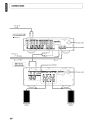
• Connection Example 3: Connection for using connecting 2 SM-11S1s in BTL mode for
stereo playback
Note:
When using this unit in BTL mode, ensure that the speakers have an impedance of more than 8Q.
CD Player
"
"
~-~;Jt
n
r'iii1
"
0
L~~
c:::;
. . . . . :. ~~=ml:
"""<""~~---"J
R ch
To BALANCED
LINE OUT jack
@
@
~
~ ~II
l.S~--~--Set to STEREO
@
@
~-::-- To power outlet
@
@
\
7
JI
@
@
@
@
\
I SM-11S1
®
for R ch I
@
/
_ - - S e t to BTL
@
@
@
@
@
Speaker R ch
Set the BALANCED button and SPEAKER 1 button on the front panel of the SM-11 S1 s for both the left
channel and right channel to ON
•
Speaker L ch
I
[
I
CONNECTIONS
]
• Connection Example 4: Stereo Complete Bi-amp Connection
1. Connect 2 Marantz SC-11 S1 by EC.B.S. for synchronized control.
For EC.B.S. connection, connect with commercially available cables with monaural
miniplugs as described in F.e.B.S. (pg. 26) in the SC-11 S1 instruction manual.
¢?
monaural miniplugs or stereo
¢?
stereo
2. Refer to the SC-11 S1 instruction manual (pg. 27) and set the SC-11 S1 ID numbers.
3. Connect the analog output of the CD player etc. to the L ch input jacks of both pre-amps. As both pre-amps operate as monaural
pre-amps in BI-AMP mode, do not use the R channel of the input jacks for the SC-11 S1 .
• About Complete Bi-Amp
Proposed by Marantz, the complete bi-amp connection is an advanced technique that enhances sound quality. The low and mid/high
amplifiers are separate and independent of the preamplifier, therefore interference between low and mid/high sounds is reduced
to a minimum. As a result, a wide sound environment can be reproduced.
Note:
Speaker systems that can be connected using complete bi-amp must support bi-amp connections. Before connecting your
speaker system, check the speaker system instruction manual, or contact the speaker manufacturer to check whether the
speakers support bi-amp connections.
I
L ch for SC-11S1
• Set to 10 1
®
®
To power outlet
"""":'~----~- Set to BI-AMP
®
Miniplug connecting cord x
2 (commercially available)
F.C.B.S.--+
F.C.B.S. +--
-~-To power
outlet
®
o
o
®
®
®
®
®
®
Remove shorting
bar
Speaker L ch
®
Remove shorting
bar
I Set the BALANCED button and SPEAKER 1 button on the front panel of the SM-11S1s for both the left channel and right channel to ON I
1.2
[~_C_O_N_N_E_C_T_IO_N_S
~]
CD Player
<II
<II
<II
R
,.
+-1
I R ch for SC-11S1
• Set to ID 2
@
@
ACIN
cf·~~
To power outlet
. . . _ - - - -......-
Set to BI-AMP
~ ~II
@
@
JI
- - . F.C.B.S.
~F.C.B.S.
I SM-11S1 for R ch
@
SYSTEM 1 OR SYSTEM:I: .. · , otitiS
BTl:' OHMS
SYSTEM 1 AND SYSTEM:I : 8-16 otlMS
8Tl.: 11 OHMS
-~- To power outlet
@
@
@
@
@
Remove shorting
bar
Speaker R ch
@
Remove shorting
bar
I
13
Set the BALANCED button and SPEAKER 1 button on the front panel of the SM-11 51 s for both the Lch (left channel) and Rch (right channel) to ON
I
[
I
CONNECTIONS
]
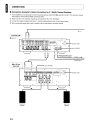
• Connection Example 5: Basic Connection for 5.1 Multi-Channel Playback
1. Three amplifiers are connected by F.C.B.S. for synchronized use. Refer to F.e.B.S. (pg. 26) in the SC-11 S1 instruction manual,
and prepare 3 commercially available connecting cables.
2. Refer to the SC-11 S1 instruction manual (pg. 27) and set the SC-11 S1 ID numbers.
3. Connect the outputs of players that have 5.1 channel analog outputs to each of the three pre-amps.
4. When using a sub-woofer with a built-in amplifier, see the sub-woofer's instruction manual.
For front UR
• Set to ID 1
@
@
ACIN
To power outlet
Set to STEREO
@
Miniplug connecting cord x
3 (commercially available)
F.C.B.S.----+
F.C.B.S. +--
SM-11S1 for
Front UR
_ - - - Set to STEREO
",,,:,,,~~,,,.~
@1li1:.:i.'..,
".":".~~,,,.~
\.
Jt:
~
~
'@
I
~'iI~
@
Front R ch
Speaker
14
r:STEAEO
I r BTL
~
.
@
SYSTEM 1 Oil SYSTEM 2 : " •• OHMS
BTL,. OHMS
SYSTEM 1 AND SYSTEM 2 : 8-11 OHMS
BTL: 1& OHMS
lti:9
~~-To
@
@
@
@
@
@
Front L ch
Speaker
power outlet
J
['-_C_O_N_N_E_C_T_IO_N_S
I
Super Audio CD Multi-channel Player etc.
MULn CHANNEL AUDIO OUT
@@D
0
>
101 0
B
A
00
.__
FRONTR
FHONTL
SURROUNOR SURRQUNDL. SU8-WOOFER
~R
7777f 7
@@@@
@
______
U
tt_I_T~
2
I
S
•
<
For centerl
subwoofer
• Set to 102
@
@
AC IN
To power outlet
-:-~---~ Set to STEREO
@
@
JI
To pg. 16
-------.
SM-11S1 for
center
_ - - - Set to STEREO
@
SYSnM 1 OR SYSTEM 2 : • _. Cl+'IMS
SySTEM 1 AND SYSTEM 2 : 8-1' OHMS
~.......
BTl-:' OHMS
an: 16 OHMS
@
To power outlet
@
o
@
@
@
@
@
@
•
Center speaker
•
@
To line input
jack
Amplifier built-in
subwoofer
15
I[
]
CONNECTIONS
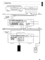
From pg. 15
-----+
I For surround UR I
• Set to 10 3
To power outlet
g
@
@
PHONO
GNO
i
Set to STEREO
@JI
@
-~ f
From pg. 15
-----+ EG.B.S.
+ - - EG.B.S.
+--
SM-11S1 for
surround UR
Set to STEREO
@
@
I
@
•
Surround R ch
Speaker
%:::n
IAOH
it:!.!
&
16
7
,,@
To power outlet
@
@
~
@
@
@
@
@
•
Surround L ch
Speaker
J
['--_C_O_N_N_E_C_T_IO_N_S
SPEAKER POSITIONING FOR SUPER
AUDIO MULTI-CHANNEL SOUND
In order to enjoy Super Audio CD multi-channel sound with
the best possible acoustics, it is recommended to position
speakers as specified in ITU-R BS.775-1 of the International
Telecommunication Union (ITU). Super Audio CD multi-channel
discs are recorded and mixed so as to achieve the optimum
effect with a speaker system laid out as specified in ITU-R
BS.775-1.
o With Super Audio CD multi-channel discs, the music signals
are basically recorded using 5 channels (3 - 6 channels
sometimes), but in some cases, LFE (for subwoofer) is
recorded as a sixth channel. Each disc indicates how many
channels have been recorded on it.
o The basic layout is 3 speakers in the front and 2 in the back
since multi-channel discs usually have 5 channels. The 2
front, 1 center and 2 surround (rear) speakers should be set
in a circle around the listening point as shown below. If using
speakers of differing sizes, adjust volume balance from the
amplifier.
o The location of the subwoofer in the figure is just for
explanatory purposes. It can be located anywhere in the
room. For connection and positioning instructions, see the
instruction manual that came with the subwoofer.
•
(CONNECTINGTHE POWER SUPPLY
J
1. Plug the power cable into AC IN jack on the back panel.
2. Turn on the power switch of the audio unit (amplifier, etc.)
that is connected with this unit. Set the selector on the
connected unit to this unit.
3. Plug the power cable into an AC outlet.
ITU (International Telecommunication Union)
The ITU is a special organization of the United Nations. It
consists of a number of organs, one of which is the Radio
Broadcasting Section.
ITU-R BS in the recommendation which consists of standards
relating to broadcasting (audio) operations, one of which is the
ITU-R BS.775-1 which governs "multi-channel stereo sound
systems."
Sub-woofer
II
~
Center
speaker
Front speaker
(Left)
17
I
I
['--H_O_W_T_O_US_E_A_N_D_S_E_T_F_E_A_J'U_R_E_S
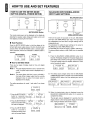
HOW TO USE THE METER MODE
BUTTON (DIGITAL POWER METER)
J
BALANCED INPUT/UNBALANCED
INPUT GAIN SETTINGS
BALANCED Button
marantll
0
~
Q
~
Q
e
c ;....-0
0
~
Q
CO
~
~
Q
'\........ 1"••/
METER MODE Button
The actual output power can be displayed on the display by
detecting the speaker output voltage and output current, and
then digitally processing the information.
• Hold Function
Press the METER MODE button to hold the display of the
left and right power output status at the time the button was
pressed. When the METER MODE button is pressed again,
hold is released. (Hold is also released if a different button is
operated.)
Normal display
e il
Wlarant'll
e
0
e
0
CO
~
~
UNBALANCED Button
There are two types of input jack on this unit, BALANCED
jack input and UNBALANCED jack input. The input types
are independent from each other, and gain settings can be
independently set.
The procedure for setting the gain settings is the same for
BALANCED input and UNBALANCED input.
The standard gain can be set across a +6dB to -6dB range.
The factory default setting is ±OdB (23dB) from the standard
gain.
In Hold
L POWER R
L HOLD
R
• How to Set Meter Mode
There are two types of display mode for this unit's digital
power meter.
Mode 1: The power display hold time is set to 1 second in this
mode. The power output value is displayed every 1
second.
Mode 2: The power display hold time is set to unlimited in
this mode. When a larger output than the currently
displayed value is output, that output value is
displayed on the display.
1. Press the BALANCED (UNBALANCED) button for 3
seconds. The display changes from the power display to the
gain setting mode, and the current gain value is displayed.
In the gain setting mode, the amplifier switches to mute,
and no sounds are output.
L POWER R
--
BRLRNCED
2. The setting value changes every time the BALANCED
(UNBALANCED) button is pressed. Press the BALANCED
(UNBALANCED) button until the desired gain value is
displayed.
BHLHt·iCED
The setting procedures for mode 1 and mode 2 are shown
below.
t
_
3. When the desired gain value is displayed, press the
BALANCED (UNBALANCED) button for 3 seconds to
complete the setting.
CD Press the METER MODE
button for 3 seconds to
display the current mode.
"--'---=--.::.---=;::-_----=.J
CV Press the METER MODE
.----;:-:;-;:-:!-;:-;=:---,
button once and the newly
set mode is displayed.
G) Press the METER MODE
button for 3 seconds to
complete the setting, and to
return to the power display.
18
The set gain value is displayed for 3 seconds, then the
display returns to the normal power display. At the same
time, muting is released, and sound is output.
BHLHt·jCED
F' 0 i.l,l EF.~
_
C:"i Ci......
(:i
.......
---------~]
[ H_O_W_T_O_U_S_E_A_N_D_S_E_T_F_E_A_:T_U_R_E_S
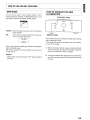
[~A_M_P_M_O_D_E
~}
This unit can be used in normal stereo mode or in BTL
monaural mode by switching the AMP MODE switch on the
rear panel to match the connected speaker system.
. .
HOW TO OPERATE THE SIDE
ILLUMINATION
Illumination Lamp
I
..
-0
r=STEREO
~O
Ir BTL
[@]
<:)
0'
STEREO: Set to this mode to use the unit as a normal stereo
power amplifier.
BTL:
Set to connect a stereo amp by BTL and use the
unit as a monaural power amp.
e
lfta.-an1I
Do
'0
'0
(0
"'"'"
I~
~/
DISPLAY button
The illumination lamp has an always-ON mode (factory setting)
and an always-OFF mode.
In the always-ON mode, the illumination lamp turns ON/OFF
in sync with the display.
When in BTL mode, the amplifier gain increases by +6dB higher
than the STEREO mode.
Alter the gain settings to suit the conditions in which the unit
is used. (pg. 18)
Caution:
Always make sure that the power is OFF before switching
this switch.
1. With the illumination lamp lit, press and hold the DISPLAY
button for 3 seconds or longer. The illumination lamp goes
out, and the always-OFF mode is engaged.
2. To cancel the always-OFF mode and turn the illumination
lamp ON, press and hold the DISPLAY button for 3 seconds
or longer.
1.9
I
I (
I [
]
HOW TO USE AND SET FEATURES
2. Check that the power to the unit and SC-11 S1 that will be
connected to it are both OFF.
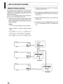
REMOTE POWER CONTROL
By connecting this unit to a Marantz SC-11 S1 stereo control
amplifier using the remote power control connection, the power
controls of this unit are operated in sync with the SC-11S1
power ON/OFF controls.
The SC-11 S1 has two trigger output terminals, therefore two
SM-11 S1s can be connected to one SC-11S1.
3. After completing the connections shown below, switch the
remote power control ON/OFF switch on the rear panel of
the unit to ON.
4. Press the POWER ON/OFF switch on the unit to switch to
standby mode.
1. Prepare the correct number of double-ended mini plug
audio connection cables for the number of SM-11 S1s to
be connected. Either of the following types of connection
cables are adequate.
5. In this condition, press the POWER ON/OFF switch on the
SC-11 S1, and the power of the SM-11 S1 will switch ON in
sync.
Caution:
Do not use connecting cables that contain resistance.
• Monaural mini plug q
cable
monaural miniplug connecting
~)IDIIIIIDIIIlIrr:III~===4\1\):::====OilnnlllllIIllllIlI~
• Stereo miniplug q stereo miniplug connecting cable
~J][III1IIIIDIIIIDli===~\\:\====OilnnllllilIITIlll~
SC-11S1
.o
~';'~
TRiGGER OUT
1
2
I
@@
A A
~~~,'
----""""'
SM-11S1
~
SM-11S1
r 'O"·[,j~l
20
~ fy-~-u-e~-p-~-ie-o~-e-~-ou-~-,eE-w-;~-t-h~-s-~- -,~-s-~-m-I~-ke-~-he-b-e-IO-W- .-P-r-o-te-c-t-iv-e-C-ir-cU-i-ts- - - - - - - -]
checks before thinking the worst. Improper operation can
cause the SM-11 S1 to behave in a way that makes you think
something is wrong with the equipment when actually not. If
the trouble cannot be fixed after making the below checks,
contact the place of purchase, your nearest Marantz dealer,
our customer service center or our repair service center.
• Power does not turn ON
1. Is the power cable securely plugged into a power outlet?
2. Is the remote power control switch on the rear panel set
correctly?
This unit is equipped with protective circuits to protect the
amplifier circuits and speaker system against damage. If a
protective circuit trips, the sound is instantly muted. In this
case, "PROTECT" flashes on the display and the STANDBY
indicator also flashes.
• At Power ON
For about 8 seconds after power is activated, a protective
circuit trips and mutes the sound to give amplifier circuits time
to stabilize. Once the amplifier circuits stabilize, the protective
circuit releases and audio is enabled.
• Nothing is heard from the speakers
• In the Event of Over current
1. Is the SPEAKERS button on the front panel OFF?
A protective circuit trips if current that exceeds the set level is
detected, which can happen if excessive signal flow is input to
the amplifier, or if the unit is connected to a speaker system of
less than 4Q impedance. A protective circuit can also trip if a
speaker cable accidentally shorts. In these cases, "PROTECT"
flashes on the display, and the STANDBY indicator flashes red.
To release the protective circuits, switch the power OFF, and
wait for approximately 1 minute before switching the power
back ON again.
2. Is the input set correctly using the BALANCED button or
UNBALANCED button on the front panel?
3. Is the gain switching mode in use causing sound to be
muted?
4. Are connection cables and speaker cables securely
connected?
5. A protective circuit may have tripped causing sound to
be muted. If PROTECT is flashing in the display, switch
the power off and wait for approximately 1 minute before
switching the power on again.
• Sound from the speakers is not stereo
The MODE switch on the rear panel may be set to BTL. If the
switch is set to BTL, switch off the power, change the AMP
MODE switch to STEREO, and then switch the unit's power
back on again.
• If Strong Bass Signals Are Input
A protective circuit trips if bass signals of an excessive level
are detected.
In these cases, "PROTECT" flashes on the display, and the
STANDBY indicator flashes red. To release the protective
circuits, switch the power OFF, and wait for approximately 1
minute before switching the power back ON again.
• If the Amplifier Overheats
A protective circuit trips if the temperature of the main amplifier
rises above the set level, which can happen if excessive signal
flow is continually input into the amplifier. Temperature can
also exceed the trip level of the protective circuits if the vents
on the top of the unit are covered, or if the unit is installed on
a cramped audio rack. In these cases, "PROTECT" flashes
on the display, and the STANDBY indicator flashes red. To
release the protective circuit, switch off the power supply and
wait for the amplifier to cool to operational temperature before
switching the power on again.
• In the Event of Amplifier Trouble
A protective circuit trips and automatically shuts off the power
if an abnormality is detected in the power circuit for whatever
reason. The same happens if the main fuse inside the amplifier
blows. In these cases, the STANDBY indicator on the display
flashes red.
Switch off the power supply, and wait for a few minutes before
switching the power on again. If the display does not light and
the STANDBY indicator continues to flash after switching the
power on again, the unit has a fault.
21
I
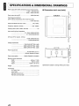
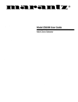
[ SPECIFI;CATIONS·& DIMENSIONAL. DRAWINGS
Power output (20Hz-20kHz simultaneous drive of both channels)
.............................................. 11 OW +11 OW (8Q load)
............................................. 220W + 220W (4Q load)
Power output during BTL
e
]
Dimensions (unit: mm (inch»
LO
C\J
420W (8Q load)
Total frequency distortion
(20Hz-20kHz simultaneous drive of both channels)
.......................................................... 0.02% (8Q load)
Output bandwidth (8Q load, 0.05%)
5Hz-40kHz
Frequency response (1 W, 8Q)
5Hz-120kHz
Damping factor (20Hz-20kHz, 8Q load)
o
11 0
(j)
o
C\J
~~
Input sensitivity/Input impedance
........................................ 2V / 22kQ (UNBALANCED)
............................................. 2V / 22kQ (BALANCED)
SIN rate (IHF-A network, 1W, 8Q)
............................................. 101 dB (UNBALANCED)
................................................... 101 dB (BALANCED)
Voltage amplification
..................................... 17dB (GAIN SETTING: -6dB)
.................................... 23dB (GAIN SETTING: ±OdB)
.................................... 29dB (GAIN SETTING: +6dB)
~
or-
--
Power requirement
................................................AC120V 60Hz (U.S.A.)
......................................... AC230V 50/60Hz (Europe)
Power consumption
22
0
e
(f)
j
~CO
0
('t)-
a
LO
I
~<b
m";::'"
0-
~cx:>
..--~
0
"::=:::7
r
~
7
j~
440mm (17-3/8)
168mm (6-5/8)
429mm (16-15/16)
Weight
Accessories
AC Power Cord
User Guide
Warranty Card (U.S.A.)
Warranty Card (Canada)
e
~
ftlapanlX
380W (EN60065) (UL60065)
Maximum outer dimensions
Width
Height
Depth
~
440 (17-3/8)
26.6kg (58.6 Ibs)
\
1
1
1
1
~
~
~
Specifications subject to change without prior notice.
"
~ h-eO-s-e-~-iO-~-d-~-SC-~-ib-e~-th-e-c-a-re-a-n-d-m-a-i-nt-e-na-n-c-e-ta-s-ks-th-a-t ---.-R-e-p-a-i-r-s-------------~]
must be performed to optimize the operation of your Marantz
equipment.
• Cleaning of equipment external surfaces
The exterior finish of your unit will last indefinitely with
proper care and cleaning, Never use scouring pads, steel
wool, scourging powders or harsh chemical agents (e.g., lye
solution), alcohol, thinner, benzine, insecticide or other volatile
substances as these will mar the finish of the equipment.
Likewise, never use cloths containing chemical substances.
If the equipment get dirty, wipe the external surfaces with a
soft, lint-free cloth.
If the equipment becomes heavily soiled:
o dilute some washing up liquid in water, in a ratio of one part
detergent to six parts water.
o dip a soft, lint free in the solution and wring the it is damp.
o
o
Only the most competent and qualified service technicians
should be allowed to service the factory-trained warranty
station personnel have the knowledge and special facilities
needed for repair and calibration of this precision equipment.
After the warranty period has expired, repairs will be performed
for a charge if the equipment can be returned to normal
operation.
In the event of difficulty, refer to your dealer or write directly
to the nearest location to you that is listed on the Marantz
Authorized Service Station list. If writing, please include the
model and serial number of the equipment together with a full
description of what you think is abnormal about the equipment's
behaviour.
wipe the equipment with the damp cloth.
dry the equipment by wiping it with a dry cloth.
23
I
www.marantz.com
You can find your nearest authorized distributor or dealer on our website .
...a ..antz@ is a registered trademark.
Printed in Japan
09/2007 00M23AJ851310 mzh-g
_apanIZ®
MARANTZ CANADA LIMITED WARRANTY
Marantz Canada ("Marantz") warrants the following Marantz
products for the periods indicated:
Who May Enforce the Warranty
3-year warranty for both Parts & Labour, from the original
purchase date:
What We Will Pay For
Amplifiers; Pre Amplifiers; Pre Amplifier-Processor-Tuners;
Integrated Amplifiers; Tuners; Receivers; DVD Players; CDRecorders; CD Players; Audio Cassette Decks; Learning
Remote Control Devices; Universal Dock & DLP front
Projectors.
1 year warranty for parts and labour from the original purchase
date:
HD Digital VCR's
90 day warranty for parts and labour from the original purchase
date:
DLP lamps
3-year warranty for Labour, 2-year warranty for parts and 1-year
warranty for the Panel:
Plasma Displays
What is Covered and What is Not Covered
Except as specified below, this warranty covers parts and
labor to correct all defects in materials and workmanship. The
following are not covered by the warranty:
1. Damage, deterioration, malfunction or failure to meet
performance specifications resulting from:
a) Accident; acts of nature; misuse; abuse; neglect;
unauthorized product modification.
b) Improper installation, removal or maintenance, or
failure to follow instructions supplied with the
product.
c) Repair or attempted repair by anyone not authorized
by Marantz to repair the product.
d) Any shipment of the product (claims must be
presented to the carrier)
e) Any cause other than a product defect
2. Cleaning, initial set-up, check-ups with no defects found,
or charges incurred for installation, removal or
reinstallation of the product.
3. Any product on which the serial number has been
defaced, modified or removed.
Only the original purchaser may enforce this warranty.
We will pay for all labor and material expenses for items
covered by the warranty. Payment of shipping charges is
discussed in the next section of this warranty.
How You Can Get Service
1. If your unit needs service, it may be taken or shipped to
any authorized MARANTZ service station or MARANTZ
CANADA (if you are uncertain as to whether a service
station is MARANTZ authorized, please contact
MARANTZ as listed below). Please do not return your
unit to the factory without prior authorization.
2. You must pay any shipping charged if it is necessary to
ship the product for service. However, if the necessary
repairs are covered under warranty, we will pay the
return shipping charges to any destination within
Canada.
3. Whenever warranty service is required, you must present
the original dated sales receipt or other proof of date of
purchase.
Limitation of Implied warranties
All implied warranties, including warranties of
merchantability and fitness for a particular purchase, are
limited in duration to the length of this warranty.
Exclusion of damages
Marantz liability for any defective product is limited to repair
or replacement of the product at Marantz's option. Marantz
shall not be liable for damage to other products caused by
any defects in Marantz products, damages based upon
inconvenience or loss of use of the product, or any other
damages, whether incidental, consequential, or otherwise.
Some provinces do not allow limitations on how long an
implied warranty lasts and / or does not allow the exclusion of
incidental or consequential damages, so the above limitations
and exclusions may not apply to you.
This warranty gives you specific legal rights, but you may
also have other rights, which vary from province to province.
4. Accessories, including but not limited to, batteries, cables,
mounting hardware and brackets, cleaning accessories,
antenna and detachable power cords.
5. Warranty is void if purchase was made from anyone
other than an authorized Marantz dealer.
MARANTZ Canada
Division of D&M Canada Inc.
5-505 Apple Creek Blvd.,
Markham, Ontario
L3R 5B1
1-888-258-9361
www.marantz.com
PRINTED IN JAPAN
3/07
00M183J854016
_apantz®
GARANTIE LlMITEE DE MARANTZ CANADA
Marantz Canada ("Marantz") garantie les produits suivants
pour les periodes indiquees :
3 ans de garantie pour les pieces et la main d'muvre prenant
eftet it partir de la date d'achat du produit :
Amplificateurs, Preamplificateurs, Pre-ampli-processeurssyntoniseurs; amplificateurs integres, syntoniseurs,
recepteurs, lecteurs DVD, enregistreurs CD, lecteurs CD,
piatines a cassette audio, telecommandes programmables,
Dock universel et projecteurs avant DLP.
1 an de garantie pour les pieces et la main d'muvre prenant
eftet it partir de la date d'achat du produit :
Magnetoscope numerique HD
90 jours de garantie pour les pieces et la main d'muvre prenant
eftet it partir de la date d'achat du produit :
Lampes DLP
3 ans de garantie pour la main d'muvre, 2 ans de garantie pour
les pieces et un an de garantie pour Ie panneau :
Ecrans a plasma
Ce qui est couvert et pas couvert par la garantie :
A l'exception de ce qui est mentionne ci-dessous, cette
garantie couvre les pieces et la main d'CEuvre afin de reparer
tous les defauts de materiel ou de fabrication du produit. Ce
qui suit n'est pas couvert par la garantie :
1. Les dommages, deterioration, defauts de fonctionnement,
ou Ie fait de ne pas respecter les specifications d'executions
resultant d'un (e) :
a) accident, acte de la nature, abus, negligence, utilisation
impropre ou d'une modification de produit non
autorisee;
b) installation incorrecte, deplacement, maintenance ou
d'un emploi contraire aux instructions fournies avec
Ie produit;
c) reparations ou tentatives de reparations par une
personne non reconnue par Marantz;
d) envoi de produit (les reclamations doivent €tre
presentees au transporteur)
e) cause autre qu'un defaut de produit.
2. L'entretien, l'installation initiale, toute verification de produit
ou aucun defaut n'a ete trouve, ou tous £rais encourus pour
l'installation, Ie deplacement ou la reinstallation du produit.
3. Tout produit dont Ie numero de serie a ete efface, modifie
ou enleve.
4. Les accessoires incluant mais non limites aux, piles,
cables, materiaux de support, accessoires de nettoyage,
antennes et cordons de secteur detachables.
5. La garantie n'est pas valable si I'achat a ete fait au Canada
chez un revendeur non reconnu par Marantz.
Qui peut faire appliquer la garantie
Seule la personne qui a achete Ie produit a l'origine peut faire
appliquer la garantie.
Notre paiement
Nous paierons tous les frais de pieces et de main d'CEuvre
pour tous les produits couverts par la garantie. Le paiement
des frais de livraison est aborde dans la section suivante de
cette garantie.
Comment vous pouvez obtenir Ie service de reparation
1. Si vous avez besoin de faire reparer votre appareil, vous
pouvez I'envoyer ou Ie deposer chez un atelier de service
autorise Marantz ou directement chez Marantz Canada
(Dans Ie cas ou vous n'etes pas sur de savoir si un atelier de
service est autorise ou non a reparer votre appareil, vous
pouvez contacter Marantz Canada a l'adresse et au numero
de telephone ci-dessous). Veuillez ne pas renvoyer votre
appareil a l'usine sans autorisation prealable.
2. Vous devez payer les frais de livraison dans Ie cas OU votre
appareil a besoin d'etre envoye au service des reparations.
Toutefois, si les reparations necessaires sont couvertes par
la garantie, nous payerons les frais de retour d'expedition
et ce quelle que soit la destination au Canada.
3. Lorsque vous envoyez votre appareil pour un service
sous garantie, vous devez joindre une copie de la facture
d'achat (ticket ou autre preuve d'achat)
Limites des garanties implicites
Toutes les garanties implicites, y compris les garanties de
valeur marchande et specifique pour un achat particulier,
sont limitees dans la duree a la longueur de cette garantie.
Exclusion des dommages
La responsabilite de Marantz est limitee pour n'importe quel
produit defectueux en ce qui concerne la reparation ou Ie
remplacement du produit en question. Si des dommages
interviennent a des produits autres que ceux de Marantz,
Marantz ne sera pas tenu responsable des dits dommages,
bases sur Ie derangement ou la perte d'utilisation du produit
ou tout autre dommage qu'il soit fortuit, indirect ou autre.
Certaines provinces ne permettent pas de limites quant a la
duree d'une garantie sous-entendue et/ou ne permettent pas
l'exclusion de dommages fortuits ; ainsi les limitations et les
exclusions mentionnees ci-dessus peuvent ne pas s'appliquer
a votre cas.
Cette garantie vous donne des droits legaux specifiques, mais
vous pouvez aussi avoir d'autres droits qui peuvent varier
d'une province a l'autre.
Cette garantie n'est seulement valable qu'au Canada.
MARANTZ Canada
Division of D&M Canada Inc.
5-505 Apple Creek Blvd.,
Markham, Ontario
L3R 5B1
1-888-258-9361
www.marantz.com
PRINTED IN JAPAN
3/07
00M183J854016
CTEPEO ynPABJI.SIIOIUIIH YCIIJIIITEJIhl
CTEPEO YCIIJIIITEJIh MOIIJ:HOCTII
Marantz SC-llSl/SM-llSl
t:P(PYKOBO.QCTBO
T
no 3KCnllYATAI...l~U1)
~
ASI 46
Bbl np1406pen14 yCTPOL.1CTBO YC14n14TenbHOe/npeo6pa30BaTenbHoe np0143BO,QCTBa KOMnaH1414 "O&M Xon,Q14HrC VlHK",
F1nOH14A ("0 & M Holdings Inc.", Japan). MO,Qenb 8C-11 81 18M-11 81 ABnAeTCA cTepeo ynpaBnAIOLl.I14M YC14n14TeneMI
cTepeo YC14n14TeneM MOLl.lHOCT14 14 npe,QHa3Ha'-leHa ,[InA YC14neH14A aY,Q140C14rHanOB B ,QOMaWH14X aY,Q140C14CTeMax. 3TO
143,Qen14e W14pOKO 143BeCTHO B Kpyrax 14CTIt1HHbIX ueHIt1TeneL.1 BblCOKOKnaCcHoro 3ByKa. Ka'-leCTBO 14 6e30nacHocTb
nO,QTBep)f(,QeHbl MHO)f(eCTBOM TeCTOB, npOBe,QeHHblx KaK 3apy6e)f(HbIM14, TaK It1 POCC14L.1CKIt1MIt1 It1CnblTaTenbHblMIt1
na60paTOp14AMIt1.
Vl3roTOBIt1Tenb B Te'-leHlt1e 3 neT (CpOK cny)f(6bl) nocne BblnycKa ,QaHHoro 1t13,Qen14A 06eCne'-lIt1BaeT Han14'-1lt1e
KOMnneKTyIOLl.I14X B uenAX B03MO)f(HOCT14 npOBe,QeHIt1A peMOHTa It1 TeXHIt1'-1eCKOrO 06cny)f(14BaHlI1A, no 14CTe'-leHIt1It1
KOTOpOro 3KcnnyaTaU14A 14 TeXHIt1'-1eCKOe o6cny)f(It1BaHlt1e npo,Qon)f(aeTCA B COOTBeTCTBIt114 C ,QeL.1CTBYIOLl.IIt1MIt1
HOpMaTlI1BHblMIt1 ,QOKyMeHTaMlI1. Vl3,Qenlt1e OCTaeTCA 6e30naCHbiM ,[InA )f(1I13HIt1, 3,Q0POBbA '-IenOBeKa It1 OKpY)f(aIOLl.IeL.1
cpe,Qbl B Te'-leHlI1e Bcero cpOKa 3KcnnyaTaU14111. rapaHTIt1L.1HblL.1 CpOK - 1 ro,Q.
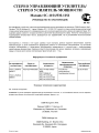
HH<lJopMa~HH 0 POCCHHCKOII cepTH<lJHKa~HH
No cepntqntKaTa
OpraH no
COOTBeTCTB~R
cepT~Q>~Ka~~~
POCC JP.AFl46.
B67917
POCTECT-MOCKBA
POCC JP.AFl46.
B68015
HopManlBHble
AOKyMeHTbl
rOCT
2002
rOCT
rOCT
rOCT
rOCT
P M3K 6006522505-97
P 51515-99
P 51317.3.2-99
P 51317.3.3-99
Ha~MeHOBaH~e
cepT~Q>~~~pOBaHHOM
npOAYK~~~
YCTpolilcTBa
yclt1nlt1TenbHblel
npeo6pa30BaTenbH ble
CpOK AeHcTB~R
cepT~Q>~KaTa
Ao 26.04.2010
OCHOBHMe TeXHH'IeCKHe xapaKTepuCTHKH
CM. B KOHue 14HCTpyKLl1414
SHV1MAHV1E: EClH-1 Sbl nplA06pem1 aY.QlAoannapaTYPY Ha.Qne)l(autero KayeCTSa, TO, no
S03spaTY lAnlA 06MeHY Ha aHanOrlilYHbl~ Tosap .Qpyrlilx pa3Mepa, epOPMbl lA T..Q.
POCClA~CKlAM
3aKOHaM, OHa He nO.Qne)l(lAT
D&M XOnAV1HrC V1HK
3AaHV1e D&M, 2-1 HV1cCV1H-T8
KasacaKV1-KY, KaSaCaKli1-CV1, KaHarasa
2108569, RnOHli1A
D&M Holdings Inc.
D&M Building, 2-1 Nisshin-Cho
Kawasaki-Ku, Kawasaki-Shi, Kanagawa
2108569,Japan
Printed in Japan
00M22AJ851 090
For U.S.A.
lDapantz®
Limited Warranty
Marantz America, Inc. ("Marantz") warrants the following Marantz
Products for the periods indicated:
Who may enforce the warranty
This warranty may be enforced only by the original purchaser.
1. The following Marantz Audio/Video components, have a 3
year warranty for both Parts & Labor, from the original purchase date:
Amplifiers, Pre Amplifiers, Pre Amplifier-ProcessorTuners, Integrated Amplifiers, Tuners, Receivers, DVD
Players, CD-Recorders, CD Players, Audio Cassette Decks,
Learning Remote Control Devices, Universal Dock & DLP
front Projectors.
2. VCR's, Wallvisions, Plasma TVs, LCD TVs & HOD
Products have a 1 year warranty for parts and labor from the
original purchase date.
3. Rear Projection TVs have a 2 year warranty for parts and
labor from the original purchase date.
4. DLP lamps have a 90 day warranty for parts and labor from
the origianl purchase date.
What is covered and what is not covered
Except as specified below, this warranty covers parts and labor
to correct all defects in materials and workmanship. The following are not covered by the warranty:
1. Damage, deterioration, malfunction or failure to meet performance specifications resulting from:
a) Accident, acts of nature, misuse, abuse, neglect or unauthorized product modification.
b) Improper installation, removal or maintenance, or failure to follow instructions supplied with the product.
c) Repair or attempted repair by anyone not authorized by
Marantz to repair the product.
d) Any shipment of the product (claims must be presented
to the carrier).
e) Any cause other than a product defect.
2. Cleaning, initial set-up, check-ups with no defects found, or
charges incurred for installation, removal or reinstallation of
the product.
3. Any product on which the serial number has been defaced,
modified or removed.
4. Batteries.
5. Accessories, including but not limited to, batteries, cables,
mounting hardware and brackets, cleaning accessories,
antenna and detachable power cords.
What we will pay for
We will pay for all labor and material expenses for items covered by the warranty. Payment of shipping charges is discussed
in the next section of this warranty.
How you can get service
1. If your unit needs service, contact Marantz service referral by
calling toll-free 1-800-270-4533. We will advise you of the
name and location of one or more authorized Marantz service stations from which service can be obtained. Please do
not return your unit to the factory without prior authorization.
2. You must pay any shipping charged if it is necessary to ship
the product for service. However, if the necessary repairs are
covered under warranty, we will pay the return shipping
charges to any destination within the United States, its possessions or territories.
3. Whenever warranty service is required, you must present the
original dated sales receipt or other proof of date of purchase.
Limitation of implied warranties
All implied warranties, including warranties of merchantability
and fitness for a particular purchase, are limited in duration to
the length of this warranty.
Exclusion of damages
Marantz liability for any defective product is limited to repair or
replacement of the product at Marantz's option. Marantz shall
not be liable for damage to other products caused by any defects
in Marantz products, damages based upon inconvenience or
loss of use of the product, or any other damages, whether incidental, consequential, or otherwise.
How state law relates to the warranty
Some states do not allow limitations on how long an implied
warranty lasts and / or do not allow the exclusion or limitation
of incidental or consequential damages, so the above limitations
or exclusions may not apply to you.
This warranty gives you specific legal rights, and you may also
have other rights which vary from state to state.
6. Warranty is void if purchase was made from anyone other
than an authorized Marantz dealer.
Marantz America, Inc.
100 Corporate Drive,
Mahwah, NJ, 07430
Phone. 800-654-6633 Fax. 201-762-6686
PRINTED IN JAPAN
6/06
3133 115 78064
092J854117