1
SEARS
Kenmore
OWNER'S MANUAL
GAS SLIDE-IN RANGE
models 36511, 36519
MNM127(346435)-2
CONTENTS
NOTICES
...................................................................................................
2
INSTALLATION
................................................................................
USEAND
3-10
CARE
Important Instructions for Your Safety ...........................................................................
Your Range and Its Features .......................................................................................
Burner Ignition ...............................................................................................................
Oven Vent ......................................................................................................................
11. 12
13
15
15
Electronic Range Control .................................................................................................
Oven Cooking .............................................................................................
Broiling .........................................................................................................
The Self-Glean cycle .....................................................................................
Cleaning Tips ..............................................................................
Removable Range Parts ............................................
14
16, 17
18
19, 20
21, 22
23, 24
SERVICE
Replacing Oven Light Bulb (some models) .................................................
What to Do before Calring for Service ................................................
Adjusting Oven Temperature ..................................................
REPAIR
How Io Order
22
25, 26
26
PARTS LIST
........................................
27
WARRANTY
GCO064
f
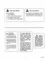
FOR YOUR SAFETY
,_
If you smell gas:
1. Open windows.
2. Don't touch electrical switches.
FOR YOUR SAFETY
Do not store or use gasoline or other
flammable vapors and liquids in the
vicinity of this or any other appliance.
3. Extinguish any open flame.
4. Immediately call your gas supplier.
\
.J
f
f
_,_ L.P. Burner
Adjustments
The adjustments in the Installation Section must be made
before you try touse your range.
If you are using Llquified Petroleum Gas (bottled gas) all
L.P adjustments in the Installation Section must be made
before use.
If your oven is not properly adjusted, flames may be too high,
orthe oven may use foe much
fuel, release toxic fumes or cook
poorly.
To insure safety for
yourself
and your
home, please read
your Owner's Manual
carefully.
Keep it
handy for quick, easy
reference.
f
,_
WARNING:
Improper Installation,
alteration, service or
maintenance can cause
Injury or properly damage. Refer to this manual. For assistance or
additional information
consult a qualified Installer, service agency,
manufacturer (dealer)
or the gas supplier.
Pay close attention to
the safety sections of
your manual. You can
recognize the safety
sections by looking for
the _, symbol or the
word "Safety".
J
J
2
GNOT16-1
INSTALLATION
INSTALLER:
appliance,
Leavetheseinstructionswiththe
OWNER:
use.
Keep these
instructions
for future
TOOL LIST
Some vinylwall tiles and floor coverings, as well as some
indoor-outdoor carpeting, soften at fairly low temperatures. If you are unsure of the heat resistance of a
material, put a protective covering under the range to
prevent possible heat damage during range use.
1/2", 1-3/16" and 1-3/8" open end or adjustable wrenches
Pipe wrench
1/8" and 1/4" flat blade screwdriver
Phillips screwdriver
Recommended location for the gas inlet pipe and electrical outlet are shown in Figure 1.
Pliers
• Seal all openings in the wall behind and the floor below
the range, before you slide the range into place.
Pencil
Rule or tape measure and straightedge
This range is designedto be installed in a30"wide opening.
See next page for dimensions. The counter opening must
be 25" deep and may be notched on each side when the
backguard is used. If the filler is used instead of the
backguard, see the following page for more information.
Hand saw or saber saw
LOCATION
• The distance from the floor to the top of the counter must
be at least 35 7/8". The maximum counter height is 38".
CLEARANCES
• You should not put the range near an outside door or
where a draft may affect use.
There must be at least 30" between the cooktop and any
overhead cabinets for an area equal to the width and
depth of the range (30" by 28").
Cabinet space directly over the range should not be used.
You could be seriously injured when reaching over the
range for items stored in such cabinets. This hazard can
be reduced by installing a range hood that projects a
minimum of 5" beyond the bottom of the cabinets. Cabinets installed above the range may be no deeper than 13".
You must keep a clearance of at least 2" between the
range sides and any material that could catch fire, from
the cooktop upward, to a height of at least 18".
Refer to Figures 1-7 for all rough-in and minimum clearance dimensions.
ALTERNATE
R_GID GAS PiPE LOCATION
7 1/4" FROM LEFT CABINET SIDE AND
33 1/2" FROM FLOOR
RECOMMENDED
ELECTRICAL
OUTLET
INSTALLATION
TO BE IN AREA 1 1/2" - 18"
FROM FLOOR AND 6" TO 20 3/4" FROM
RIGHT S/DE OF RANGE
J
RECOMMENDED
LOCATION
SIDE
AND
J
Fig
I
oc .uo, o
RIGID
GAS PIPE
1/4" FROM
FROM REAR
LEFT WALL
CABINET
17 I/2"
BY RANGE
1
Fig. 2
3
MINIMUM DIMENSIONS
BETWEEN
COOK'FOP CABINETS AND WALLS
GINS100
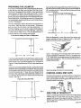
PREPARING
THE COUNTER
If you have an existing 30" wide cutout that goes all the way
to the wall you may want to buy a Main Top Filler Kit No,
80279 or a 4" Backguard Kit No. 80509. These will fill in the
space between the back of the range and the wall. The kits
are available from Sears general catalog and may be ordered at any Sears catalog outlet or the catalog desk at any
Sears Retail Store. If this existing cutout is in a counter that
has a backsplash (postformed top) we recommend that you
use the 4'* Backguard.
From the illustrations below determine the dimensions of
your cutout. Mark the cutout on the counter. Dimensions
given are from front of counter, not from cabinet face. To
minimize chipping, you may want to apply masking tape to
the counter and mark the cut on top of the tape. Use a hand
or saber saw to make the cut. For best appearance it is
important that the cut be smooth and straight.
If you wish to set the range further back into the counter, you
may notch the front of the counter up to a maximum depth of
1/2", as shown in Fig. 6. See your filler kit instructionsheet
for more information.
you are using the Beckguard
---I
24 1/2"
Fig. 5
,1
3/8"----> _ _
30"
•
1----3/8"
/
1/2"
If you are not using the Filler or Backguard
When the Backguard is used, the front of the counter may
require notching as shown in Figures 5 and 6. See backguard kit instruction before cuffing counter.
23 3/16"
1/2"
Fig. 6
Fig. 3
If you have a standard 25" countertop and you wish to set the
range further back into the counter, you may notch the front
of the counter up to a maximum depth of 1/2'" as shown in
Figure 6. Cutout should then be 23 3/16" deep from back of
notch.
If you have a countertop deeper than 25", such as in an island
installation with a countertop of at least 26" and you wish to
set the range further back into the counter, you may notch the
front of the counter up to 1" deep, but never deeper than to
the front of the cabinet face and maintaining at least 24 1/2"
from the back of the notch to the inside of the rear wall of the
counter. See Fig. 5.
If you are using the Filler
.[
l
_'
Fig. 7
See the leveling information on previous page.
CONTROL
PANEL END CAPS
If the frontof the counter is rounded, leave the curved portion
on the control panel end caps. For a square counter or a
notch, cut this portion off at the groove with pliers or chisel,
then file smooth if necessary.
TRIM f
SQUARE COUNTER
OR NOTCH
25"
30"
NOTE: If the distance from the back wall to the front of the
counter backsplash (Dimension A in Fig. 7) is greater than
1 1/8", there will be a small gap between the wall behind the
range and the backguard. This is normal and should not be
visually objectionable.
Fig. 4
SIDE TRIM EXTENSION
KIT
If there is a small gap between the sides of the range and the
cabinets (up to 1/4" each side), you can order a side trim
extension kit through Sears general catalog. Order Kit No.
80769 at any Sears catalog outlet or the catalog desk at any
Sears Retail Store.
EINS19-4
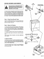
PREPARATION
1. Remove all tape and packaging.
2. Take the accessory pack out of the oven.
3. Check to be sure that no range parts have come loose
during shipping.
4. Lift the cooktop and remove the four shipping screws
from the cooktop burner. These screws may be discarded.
'it'<'----- SHIPPING SCREW
I
The range cord has a three prong plug and must be used with
a properly grounded three hole outlet with a standard 120
volt 60 hertz AC household current. Improper grounding can
affect ignition on spark ignition models.
The preferred method of electrical hook-up is shown in Fig.
8. If you do not have a grounded (three hole) outlet, have a
qualified electrician change your old outlet or install a new
one.
A grounding adapter plug may be used to convert a two hole
outlet to a three hole outlet until the grounded outlet can be
installed. (See Fig. 9). This should be done onlytemporarily
and only it the two hole outlet is properly polarized.
Do not under any circumstances
cut or remove the grounding pro ng
from the range cord. Failure to
provide proper polarization may
cause shock and fire hazard.
LEVEL
For proper baking results, the range must be leveled.
The height of the range must also be adjusted to the
height of the counter, To do this:
1. Use a 1 3/8" open end or adjustable wrench to equally
back out the four leg levelers until the flanges (rims)
below the sides of the maintop are above the top of the
counter.
2. Install the oven racks in the oven (see the Cleaning and
Care section in the manual for instructions for additional
information).
3. Place the range where it will be installed, then put a spirit
level, or a glass measuring cup partially filled with water,
on one of the oven racks to check for levelness. It using
a spirit level, take two readings with the level placed
diagonally first in one direction and then the other.
4. Usethewrenchtoadjusttheleglevelers.
Youmayhave
to pull the range away from the wall to reach the rear leg
levelers. The range should rest on the floor and not hang
from the counter.
SPIRIT
LEVEL
PLUG WITH GROUND PRONG
PROPERLY POLARIZED AND
GROUNDED RECEPTACLE
POLARIZED RECEPTACLE
PROPERLY GROUNDED
i_
L
METALEYELET
GROUND
RECEPTACLE
PL.ATE
MOUNTING
SCREW
Fig. 8
PREFERRED METHOD
.
_
_"
Ilil
._//_/_
Fig. 9
TEMPORARY METHOD
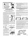
GAS CONNECTIONS
Call your gas supplier and ask which codes apply in your
area. If there are no codes, you must follow the NATIONAL
FUEL GAS CODE, ANSI/Z223.1-1988. You can get a copy
by writing:
American Gas Association
1515 Wilson Boulevard
Arlington (Rosslyn), VA 22209
ELECTRICAL
CONNECTIONS
Check with your local utilities tor electrical codes which apply
in your area. It there are no local codes, the National
Electrical Code, ANSI/NFPA No. 70-1990 must be followed.
You can get a copy by writing:
National Fire Protection Association
Batterymarch Park
Quincy, MA 02269
An adequate electrical supply and outlet must be used to
operate the electrical parts of your range.
It you are installing the range in a mobile home you must
followthe MANUFACTURED HOME CONSTRUCTION AND
SAFETY STANDARD, TITLE 24 CFR, Part 3280 (formerly
the Federal Standard for Mobile Home Construction and
Safety, Title 24, HUD Part 280). If this standard does not
apply, you must follow the STANDARD FOR MANUFACTURED HOME INSTALLATIONS 1982 (Manufactured Home
Sites, Communities and Set-Ups), ANSI A225. 1-1984 or
local codes. You can get a copy of the Standards by writing:
Office of Mobile Home Standards
HUD Building
451 7th Street, S.W.
Washington, D.C. 20410
GINS1Ol
A
Do not operate the burners of this range
when using LP. (bottled) gas before
converting the pressure regulator, burner
orifices, and oven pilot adjustment
screw, If applicable, for L.P. gas usage.
HIg h flames and toxic fumes could cause
serious Injury.
1/2" Black Iron Pipe
Shut-Off
look-Up)
Valve
90 °
Street
Ell
Know where your main gas shut off valve is.
Shut off gas supply before removing an old range. Leave it
off until hookup of new range is finished,
90 °
Stree
Ell
1/2" Black
Iron Pipe
Through Floor
Never reuse an old connector when installing a new
range.
See figures on this page for rigid and flexible pipe hookups.
1/2" X 5 114" BLack
Iron Nipple
We recommend that you use 1/2" gas supply line for both
L.P. and natural gas,
Ground Joint
Use a pipe wrench to make connections. Hold the pressure
regulator in place while installing the adjacent pipe. Do not
put any strain on the manifold regulator assembly.
RIGID PIPE HOOK-UP
FROM FLOOR OR WALL
To prevent gas leaks, put a pipe joint compound that is
resistant to the action of L.P. gas, on all male (outside)
threads except the ground joint union (see figure 10).
When you are finished making connections, be sure that all
range knobs are turned to OFF before you open lhe main gas
supply valve. Check for leaks as described below.
Fig. 10
1/2" Male
Pressure
Regu
External
Flare
Connection
TO CHECK FOR LEAKS:
Apply a soap solution to all gas connections in the supply
line, manifold (under cooktop) and oven. Bubbles will form
where any gas is leaking.
OO NOT use an open flame to look for leaks.
Turn off main gas supply before you try to stop a leak.
1/2" Black
Iron N
Turn main gas supply back on and recheck connections after
stopping any leaks.
Be sure all leaks are stopped before lighting pilots (some
models) or burners.
FLEXIBLE
CONNECTOR HOOK-UP
Fig. 11
6
GINS65-1
MAKING
L.P. GAS ADJUSTMENTS
CAP
SPRING
RETAINER
NAT.
If you are using L.P. (bottled) gas, all the
adjustments described below must be
made before you make any burner adjustments or use the range.
F-7
To adjust your range for use with L.P.gas, follow the steps
below.
t =
l
I
=
_
PRESSURE
Step 1 : Adjust Pressure
I
Iml
....
I _,.Lt,=.(
REGULATOR
Fig. A1
Step 1
Regulator
NOTE: The pressure regulator is set for natural gas. To
use L.P. gas, the regulator must be adjusted.
NAT.
Raise the cooktop and find the pressure regulator at the end
of the manifold pipe on the left side of the range.
Unscrew the cap and remove the spring retainer, Fig. A1.
Turn the retainer over and put it back into the cap so L.P. is
showing on the bottom end of the retainer. Replace the cap.
Fig. A2
Step 2
Step 2: Adjust Burner Orifices
CAUTION: The following adjustment must be made
before turning on the burner. Failure to do so could
result in serious injury due to high flames and toxic
tumes.
NAT.
Use a 1/2" open end or adjustable wrench to turn all orifice
hoods in the L.P. direction, about 1-1/2" turns or until snug,
Figs. A2, A3, and A4. Do not overtlg hten or you may bend
the orifice hood and needle.
Pressure Test Information
The maximum allowable pressure for the regulator is 14"
W.C. The minimum pressure needed to check the regulator
setting is 5" W.C. for natural gas or 11" W.C. for L.P. gas.
Fig. A3
Step 2
CAUTION: The range and its Individual shut off valve
must be disconnected from the gas supply system at
test pressures of more than 1/2 psig. (pounds per square
inch gauge).
\
The range must be isolated from the gas supply piping
system by closing its individual shut off valve during
any pressure testing of the gas supply system at test
pressures equal to or less than 1/2 psig.
Fig. A4
Step 2
7
GINS66-2
MAKING BURNER ADJUSTMENTS
AIR
SHUTTER
SHUT-OFFVALVE
IN OPEN POSITION
If you are using LP. (bottled) gas, all the
adjustments described below muSt be
made before you make any burner adjustments or use the range.
All ranges are factory adjusted for use with the most co mmon
type of natural gas. The gas used in some parts of the
country may be different. In order to assure safe and energy
efficient operation of this appliance, you should check all
adjustments described below and onthe next page. Ifyou
are using L.P. gas, all the adjustments must be made.
Step
1 : Check
Oven
Shut-off
Fig. A5
Step I
Valve
Raise the cooktop and check the oven shut-off valve in the
right front corner of the burner box, If should be in the open
position as shown in Fig. A5.
Step 2: Adjust Air Shutters
Turn all burners full on and checkthe flames. Burner flames
should not flutter or blow away from the burner. They should
be blue in color with no trace of yellow. Foreign particles in
the gas line may cause an orange flame at first, but this will
soon disappear.
If the flames are yellow or flutter, open the air shutter more.
if the flames blow away from the burner, close the shutter
more.
Check burner flames frequently
when needed.
and make adjustments
AIR
SHUTTER
To adjust air shutters:
Cooktop burners, Fig. A6 - use pliers to adjust the air shutter.
Be sure to keep the gap in the air shutter facing straight up.
Be very careful not to bend the air shutter when using
pliers to make adjustments.
Fig. A8
Step 2
Oven/broiler burners, Figs. A7 and A8 - use a screwdriver to
loosen the air shutter screw. Adjust air shutter. Retighten
the air shutter screw.
U'I-rER
AIR
Fig. A7
Step 2
8
GINS67-2
MAKING BURNER ADJUSTMENTS
NAT.
Fig. A9
Step 3
Step 3: Adjust Orifice Hoods
Check the inner cone of the flame. It should be about 11/16"
long for cooktop burners and 1/2" long for the oven/broiler
burners (see below). If the length of the inner cone ol the
flame is not correct, use a 1/2" open end wrench or adjustable joint pliers to adjust the orifice hood.
To shorten the cones, tighten the orifice hood by turning in
the L.P. direction.
To lengthen the cones, loosen the orifice hood by turning in
the Nat. direction, Figs. A9, A10 and A11.
Fig. A10
Step 3
NAT.
INNER CONE
OF FLAME
__
COOKTOP
BURNER
WARNING: if you attempt to measure
the inner cone of the flame, please use
caution. Burns could result.
\
INNER CONE
OF FLAME
112"
OVEN/BROILER
Step 4: Low Flame Adjustments (some models)
Some models have a screw in the center of the stem of each
of the cooktop burner control valves. The low position of the
cooktop burner flame can be adjusted with this screw.
Fig. A12
Step 4
To make the adjustment, turn all the cooktop burners on to
low and remove the knobs by pulling straight oil. Use a 1/8"
tlat blade screwdriver to adjust the flames to the lowest flame
that will be retained on the burner, Fig. A12.
SCREW
IN STEM
9
GINS68-1
KIT PART NO. (KIT 045) 344119
A
into the slot in the bracket (See Fig. 1), making sure the chain is
pulled as tight as possible and that there is no excess slack in the
chain after chain is attached to the bracket.
WARNING:
*
•
ALL RANGES
•
INJURY
•
INSTALL
PACKED
•
SEE INSTRUCTIONS
Excess slack in the chain could allow the range to
tip over excessively.
CAN TIP
COULD
RESULT
6) Slide the range all the way back into the counter. Once the
range is pushed back in place, there will be a small amount of slack
in the chain. This is normal.
ANTI-TIP DEVICE
WITH RANGE
IMPORTANT
INSTALLATION
INSTRUCTIONS
FOR RANGES USED WITH COUNTERTOP
HEIGHTS UP TO 38"
GAS RANGE STABILITY DEVICE
INSTALLATION INSTRUCTIONS
The height of the range must be adjusted to the countertop height.
For countertop heights greater than 37", additional measurements
may need to be taken as detailed below.
REMOVE ALL PARTS FROM THE PLASTIC BAG
ATTACHED TO THE BACK OF THE RANGE
AND SAVE PACKAGING TAPE.
WRen the range is etevated to the maximum height, there is a Iarge
space between the bottom of the range and the floor, referred to as
the toe space. This may be visually objectionable. The legs should
not be extended any further than to provide a maximum of 3" toe
space. See Fig. 1.
1) Before placing range in the counter, notice the Iocation of the
stability bracket which is already attached to the back of the range.
This location should work for r_ost instali_[;_,=s. H:_wew.r, it m_y
be more convenient to hook the stability chain to the unit when the
stability bracket is attached to the upper set of holes in the back of
the range. See Fig. 1.
2) Fasten one end of the stability
chain to the floar or the wall with
the long screw and washer supplied. See Ftg. 2. Make certain
the screw is going into the wall
plate at the base of the wall or one
of the studs in the wall. See Fig.
3. Whether you attach the chain
to the wall or floor, be certain that
the screw is in at least 3/4" thickness of wood other than baseboard and that there are no elec-
The range is designed to provide a minimum of 1" air gap at the
bottom of the range. See Fig. 2. (Example: When legs are screwed
all the way into the base rail.)
OPTIONA
LOCATION
CHAJ
Fig. 1
BRACKE_
This gap is very important to the proper ventilation of the range and
must be maintained when treating the appearance of the toe space.
BRACK
FACTORY
tricalwiresorplumbinginthearea
=.OCATION Fig. 1
MAINEIACK
in which the screw could penetrate. Attach the stability chain in a location which will allow the
chain to be in line with the bracket side to side as much as possible
when attached _o the unit. Test to see if the chain is securely
fastened by tugging on the chain,
CHAIN
The following is a suggested method of making a filler for the toe
space when the legs are extended as mentioned before.
After the range is installed with the longer legs and is in position and
level, measu re from the bottom of the bodyside to the floor. This will
be the required height of the toe space filler. See Fig. 1, This height
may range from 2-1/16" to 3". Any height less than 2-1/16" may not
be visually objectionable and not need the filler.
B_.:,=,d
',hefiiier as shown in Fig. 3. Make sure to provide the 3/4" gap
at the top and the 5/16" gap at the bottom. These gaps will provide
the proper ventilation as mentioned before.
Fig. 2
WASHER
AND
If you wish to attach the filler to the floor Dr adjacent cabinets, use
screws or other removable fasteners, so that the range can be
Fig. 3
readily removed if necessary.
3) Temporarily attach the loose
end of the chain to the rear of the
countertop with the tape from the
packaging,
See Fig. 4,
GUSSETCORNERS
WITH _4"TO
1"
TRIANGULAR OR
SQUARESTOCK
4) Placethe range inthe counter
cut out leaving just enough room
between the back of the range
and tile wall to reach the stability
bracket.
5) Hook the loose end of the
chain onto the bracket by slipping the nearest link of the chain
3/4"
AS REQUIRED
Fig. 4
10
OR AS REQUIRED
TO RECESS BEHIND
TOE A REA OF
ADJACENT CABINETS
USE 1/4" TO 1/2"
MATERIAL FINtSHED
TO MATCH TOE AREA
OF CABINETS
GINS113
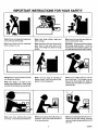
IMPORTANT INSTRUCTIONS
FOR YOUR SAFETY
Teach children not to play with range knobs
or any other part of the range.
Never store things children might want
above a range.
Never leave the oven door open when you
are not watching the range.
Never leave children alone or unattended
Never let anyone climb, sitor stand on the
open door or any other part of the
range. Their weight may make the range
tip over.
WARNING: To prevent accidental tipping
of the range, attach it to the w 'tor floor by
installing the anti-tip bracket supplied. Be
sure rear leg leveler enters slot in bracket.
Never use your range for warming or
heating a room. Such use could be dangerous and hurt range parts.
Never let pot handles stick out over the
front of the range. Turn handles in so that
they cannot be bumped into. Keep the
handles away from other hot surface elements/burners.
Never use a towel or other bulky cloth as a
potholdsr. Such cloths could catch fire on
a hot element/burner.
Never leavecooktopelementsiburners
unwatched at high heat settings. Boilovers
cause smoking and greasy spilloverscould
catch fire.
where a range is in use.
Always keep the range area clear and free
from things that will burn.
Never store things in an oven or near
cooktop elements/burners. These things
may catch fire and plastic items could melt.
Never wear loose clothing when using
your range. Such clothing could catch fire.
11
CSAF01
IMPORTANT
SAFETY INSTRUCTIONS
Keep this book for later use.
Be sure your range is installed and grounded properly by a
qualified technician.
Always keep the range area clear and free from things that
will burn, gasoline and other flammable vapors and liquids.
Only some kinds of glass or ceramic pans can be used for
cooktop cooking. Be sure that the pan you use will not break
when heated on the cooktop burners.
Always change oven rack positions while oven is cool.
After broiling, always take the broiler pan out of the oven and
clean it. Leftover grease in the broiler pan can catch on fire
next time you use the pan.
Never try to repair or replace any part of the oven unless
instructionsare given in this book. All other work should be
done by a skilled technician.
Never heat unopened food containers. Pressure buildup
may make container burst and cause injury,
Never leave jars or cans of fat or drippings near the oven.
Never let grease build up on your oven. You can keep
grease fires from starting if you clean up grease and spills
after each oven use.
Neveruse aluminum foilto line oven bottoms. Improper use
of foil could start a fire and cause incomplete combustion.
Never block the flow of combustion and ventilation air
through oven vents and cooktop burners.
Always use dry potholders when removing pans from the
oven or cooktop. Moist or damp potholders can cause steam
burns.
Never tryto move a pan of hot fat, especially a deep fat fryer.
Wait until the fat has cooled.
Never try to remove burner bowls from glass top ranges.
Always use care when opening oven door. Let hot air and
steam out before moving food.
Always follow cleaning instructions in this book.
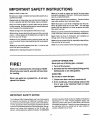
COOKTOP
FIRE!
GREASE
FIRE
Never pick up a flaming
pan...Instead:
1. Turn off the burner.
Read and understand
this information
NOW!
2. Smother the fire with a tightly fitting pan lid,
baking soda or an extinguisher.
Should you ever need it, you will not have time
for reading.
OVEN FIRE
Do not try to move the pan.
Never use water on a grease fire--it will only
spread the flames.
1. Close oven door and turn controls
off.
2. If fire continues, throw baking soda on the
fire or use a dry chemical foam or halon
type extinguisher.
IMPORTANT
SAFETY
NOTICE
and soot, caused primarily by the incomplete combustion of
natural gas or L.P. fuels. Properly adjusted ranges, indicated by a bluish rather than a yellow flame, will minimize
incomplete combustion. Exposure to these substances can
be minimized further by venting with an open window or
using a ventilation fan or hood.
The California Safe Drinking Wafer and Toxic Enforcement
Act requires the Governor of California to publish a list of
substances known tothe state to cause cancer, birth defects,
or other reproductive harm and requires businesses to warn
customers of potential exposu re to such substances. Gas appliances can cause minor exposure to four of these substances, namely benzene, carbon monoxide, formaldehyde
12
GSAF02-7
YOUR RANGE
IMPORTANT: The model and
serial number of your range
can be found on a tag, behind
the drawer panel, on the left
side of the range front irame.
Copy the numbers into the box
on the cover of this manual.
1. Oven Vent (area may get hot during range use;
DO NOT block vent)
7. Removable Oven Door
8. Oven Door Gasket (see self-clean section)
2. Removable Cooktop Burners
9. Removable Storage Drawer
3. Super Burner (see cooktop cooking section)
10 Removable Cooklop Controls
4. Electronic Range control (see next page)
11 Chrome Drip Bowl Liners
5. Oven Light Switch
12 Lift-up Cooktop
6. Removable Oven Bottom
13. Removable Burner Grates
13
GSIF02
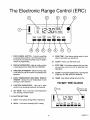
The Electronic Range Control (ERC)
i
©
CANCEL
STOP
COOK
TIMER CLOCK TIME CLEAN TIME BROIL BAKE
1,
OVENCANCEL
BU'I-FON - Cancels everything
except the clock and timer. Push this button to turn
the oven off or to clear everything if you've made a
mistake in programming.
2.
DISPLAY INDICATORS - Light upto tell you what
is being shown in the TIME DISPLAY WINDOW.
3.
TIME DISPLAY WINDOW - Shows the time of day
or the times you set for the timer or automatic oven
operation.
4.
OVEN TEMPERATURE
AND BROIL DISPLAY
WINDOW - Shows the oven temperature or broil
setting you have selected.
5.
FUNCTION INDICATORS - Light up to show
whether oven is baking, broiling or self-cleaning
6.
SET KNOB - Turn to set times and temperatures
after pushing a function button.
9.
COOK TIME - Push before setting length of cook
time for automatic oven operations.
10.
CLEAN - Push to use self-clean cycle.
11.
STOP TIME - Push before selecting the time when
you want the oven to turn off for automatic oven
operations.
12.
CLOCK- Push before setting clock or to bring time
of day into the TIME DISPLAY WINDOW.
13.
TIMER - Push before setting amount of time.
TO SET THE CLOCK
, Push
_Turn to set
time of day
7-13 FUNCTION BUTTONS
7.
BAKE - Push before setting BAKE temperature.
8.
BROIL - Push before selecting BROIL setting.
TIMER
14
STOP
TIME
CLEAN
GGOK
BROIL
TIME
BAKE
CERC01-2
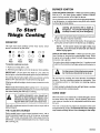
BURNER IGNITION
COOKTIP SPARK IGNITION --When you turn the cooktop
knob to LITE, the spark igniter makes a series of electric
sparks (ticking sounds) which light the bumer.
During a power failu re the burners will not light automatically.
In an emergency, a cooktop burner may be lit with a match
by following the steps below.
To Start
Things Cooking
dangerous. You should match light the
Lighting gas burners with a match is
cooktop burners only In an emergency.
1. Light a match and holdthe flame near the burner you want
to light. Wooden matches work best.
2. Push in and turn the control knob slowly. Be sure you are
turning the correct knob for the burner you are lighting.
COOKTOP
The sign near each cooktop control knob shows which
burner is turned on by that knob.
O0
O0
O0
O0
O0
O0
O0
O0
Left
Rear
Left
Front
Right
Rear
Right
Front
NOTE: If the burner does not light within five
seconds, turn the knob off and wait one minute
before trying again.
OVEN GLOW BAR IGNITION -- When you turn the Lower
Oven Control on, the glow bar igniter begins to heat. When
the igniter is hot enough, in about 1 minute, the gas flows into
the burner and is ignited.
The igniter glows bright orange when hot. It cycles on and
off with the thermostat and will glow whenever the burner is
on.
To operate cooktop controls:
1. Push to turn knob left to LITE.
2. After the burner lights, turn knob to desired flame setting.
IMPORTANT:
Do not leave the knob on LITE after the
burner lights,orthe lifeof the spark igniter may be shortened.
,_
If a cooktop burner fails to light within five seconds, turn the
knob to OFF and wait one minute before trying again.
Be sure that the cooktop and oven burners are adjusted
properly. See the installation section for information. See
the cleaning section for information on cleaning coektop
burners.
If the burner still will not light, check the service section in this
manual.
A clean, properly adjusted burner will light faster, use less
gas and give better cooking results.
Watch foods when heating them quickly on HI. As soon as
the food reaches cooking temperature, turn down the heat to
the lowest setting that will keep it cooking.
,_
OVEN VENT
When the oven is on, heated air is vented through a vent in
the panel behind the cooktop. On the cooktop, this hot air
may make pot handles hot or melt plastic items left too near
the vent.
controls
so flame
heats pan
As a safety
precaution
you bottom
should only
set
and does not lick pan sides. Flames licking pan sides are unsafe and waste heat.
Cook with a minimum amount of water and use a pan with a
tightty fitting lid.
THE
12,000
BTU
be
lit and
you should
not burner
try to do
so.
During
a power
failurethe
cannot
The vent is necessary for proper air circulation in the oven
and good baking results. Do not block this vent. Doing so
may cause cooking failure, fire or damage to the range.
BURNER
Some models have a cone-shaped cooktop burner, with a
circular opening through the center of the burner, at the right
front. This burner can provide 30% more power than the
other three. Use it for cooking large amounts of lood in a big
pan, canning, etc.
15
GMTC33
DELAYED BAKE CYCLE
TO BAKE OR ROAST
PUSH WHEN
FINISHED
TURN TO
SETLENGTH
OFCOOK
TIME
TURN TO
SET TEMP
T_ER
TURN TO
SETOVEN-TURN OFF
TIME(TIME
OF DAY)
TURN TO
SET TEMP
CLOCKSTOP
COOK
TIME CLEAN TIME BROIL BANE
PUSH
PUSH
The red display will show the oven temperature as it rises (in
5° steps).
TO USE THE TIMER
OVEN OFF
TURN TO SET
LENGTH OF I
COOK TIME
PUSH
When cook time has ended, a tone will sound and the oven
will turn off.
Atone will sound when the oven is ready.
AUTOMATIC
PUSH
TURN TO
SET AMOUNT
OF TIME
TURN TO
SET TEMP
orE. -_l.n n 3oDo
T,., ___LI LI
SET
TIMERCLOCKSTOP CLEANCOOKBROILBAKE
TIME
TtME
PUSH
PUSH
PUSH
The control will calculate when to turn the oven off.
A tone will sound when time is up.
When the stop time is reached, a tone will sound and the
oven will turn off,
NOTE: Thetlmerlsaremlnderonlyandwillnotoperate
the oven.
INCOMPLETE OR INCORRECT
SETTINGS
1.
2.
CANCELLING TONES
If you prefer that your range not have a tone whenever you
push a button, you can eliminate those tones by pushing and
holding the CANCEL button until you hear a beep. Repeat
to activate tones again.
Attention Tone will sound if oven has only been partially
programmed. For example, il you have selected acook
time but no temperatu re, you will hear the Attention Tone
until you select a temperature or push CANCEL.
PREHEATING
OPERATIONS
Function Error Tone will sound if there is a problem with
oneofthe range functions. Cancel the tone bypushing
the CANCEL button. If the tone starts again, call for
service.
RECALLING
PUSH AND HOLD
3 SECONDS TO CANCEL
FOR AUTOMATIC
OVEN
Cook times programmed for automatic oven operations start
counting down when the oven first comes on, not when it has
reachedthe set temperatures. It takes 10to 15 minutes to
reach the set temperatu re, thus additio nal cook time may be
necessary.
FUNCTIONS
You may recall any set function by pushing the button of that
function.
16
CCTL01-8
Let the oven preheat thoroughly before cooking baked
products. Allow 15 minutes preheat time.
Opening the door too often to check food during baking
will allow heat loss and may cause poor baking results.
Cakes, cookies, muffins, and quick breads should be
baked in shiny pans -- to reflect the heat -- because
they should have a light golden crust. Yeast breads and
pie crusts should be baked in glass or dull (non-shiny)
pans -- to absorb the heat -- because they should have
a brown, crisp crust.
Be sure the underside of the pan is shiny too. Darkened
undersides will not reflect the heat and may cause over
browning on the bottom of your food.
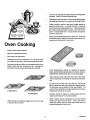
Oven Cooking
Always follow recipe carefully.
Measure ingredients properly.
Use proper pan placement.
Place pans on the oven racks with 1" to 1 1/2" of air space
on all sides of each pan. Avoid overcrowding the oven.
Pans too close to each other, to oven walls or to the oven
bottom, block the free movement ol air. Improper air
movement causes uneven browning and cooking.
Oven temperatures should be reduced 25 degrees
below recommended temperatures if exterior of pan is
predarkened, darkened by age or oven proof glass.
There may be some odor when the oven is first used.
This is caused by the heating of new pads and insulation.
2 cake layers
i-
.i-
Do not cover an entire oven rack with foil. The loll can
block normal heat flow and cause poor baking results.
Do not place any foil directly on the oven bottom. Foil
used on the oven bottom may damage the oven surface;
therefore, it should not be used.
_.._--_,,-
4 cake layers
Cookies should be baked on cookie sheets with low
sides to allow the air to circulate property.
When recipes require preheating, have food nearby
before you open the oven door. If the oven door is
allowed to remain open for more than a brief time, the
preheat temperature will be lost.
When baking several items stagger pans so that no pan
is directly above another.
17
GOVC02-2
Broiling
Never leave a soiled broiler pan In the range. Grease
in the pan may smoke or burn the next time the oven is
used.
Be sure you know the correct procedure for putting
out a grease fire. See the section on safety.
TURN TO
_SET HI OR
LO BROIL
PUSH WHEN
FINISHED
Do not cover the entire broiler grid
with foil. Poor drainage of hot fat
may cause a broiler fire.
If a fire starts, close the oven door
and turn controls off. If fire continTIMER CLOCK STOP
TIME
CLEAN
mmm mm
m
m
COOK
TIME BROIL
n
ues, throw baking soda on the fire.
Do not put water on the fire.
BAKE
III
POSITIONING
'PUSH
Most foods can be broiled at the HI Broil Setting. Select the
LO Broil setting to avoid excessive browning or drying of
foods that should be cooked to the well-done stage (such
as thick pork chops or poultry).
BROILER PAN
Rack
Position
Food
Broiling is cooking by direct heat from the broil burner.
Tender cuts of meat or marinated meat should be
selected for broiling. For best results steaks and chops
should be at least 3/4" thick.
Total Time
4 = Highest
1 = Lowest
(minutes)
Rare
4
10-12
Medium
3
14-16
Well Done
3
20-22
Medium
3
11-13
Well Done
3
13-15
Steak - 1" Thick
After placing food on the broiler pan, put the pan on the
rack in the lower broiler compartment. The recommended rack position and cooking time can be tound
in the chart at right.
The closer the food is to the broil burner, the faster the
meat browns on the outside, yet stays red to pink in the
center. Moving the meat farther away from the burner
lets the meat cook to the centerwhile browning outside.
Side one should be cooked 1 - 2 minutes longer than
Ground Beef Patties
side two.
Lamb Chops - 1" Thic&
3
16-20
Your oven and broiler doors should be completely
closed while broiling.
Pork Chops - 1" Thick
3
20-25
Pork Shoulder Steaks
3
15-20
Ham Slice - 1/2" Thick
3
14-16
Fish (Fillets)
3
10-15
Do not preheat when broiling. For even broiling on
both sides, start the food on a cold pan.
Chicken (Halves)
1
40-60
Trim the outer layer of fat from steaks and chops. Slit
the fatty edges to keep the meat from curling.
Frankfurters
3
10-15
Bacon
3
5-7
Open-face Sandwiches
2
6-10
Use only the broiler pan and grid that came with your
range for broiling. They are designed for proper drainage of fat and liquids and help prevent spatter, smoke
or fire.
For maximum juiciness, salt the first side just before
turning the meat. Salt the second side just before
serving.
Brush chicken and fish with butter several times as they
broil. When broiling fish, grease the grid to prevent
sticking and broil with skin side down. It is not necessary to turn fish.
18
This chart isa general guide. The size, weight, thickness,
and starting temperature of the food as well as your own
personal preference will affect the cooking time. Times in
the chart are based on the food being at refrigerator temperature.
GBRLO5-1
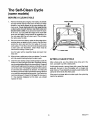
The Self-Clean
(some models)
Cycle
BEFORE A CLEAN CYCLE
FRONT FRAME
Remove the broil pan and grid, oven racks, all utensils
and any foil that may be in the oven. Do not try to clean
utensils or any other objects in the oven during a selfclean cycle. If oven racks are left In the range during
a clean cycle, they will darken, lose their luster and
become hard to slide. If you choose to leave the racks
in the oven, you can polish the edges of the racks with
steel wool and apply a small amount of vegetable oil to
the rack edges after the self-clean cycle. This will make
the racks easier to slide.
1o
2° Soil on the oven front frame, under the front edge of the
cooktop (does not apply to built-in ovens), the door liner
outside the door seal and the front edge of the oven
cavity (about 1" into the oven) will not be cleaned during
a clean cycle (see illustration). Clean these areas by
hand before starting a clean cycle.
DOOI
/
DOOR UNER
Use hot water with a soap-filled steel wool pad, then
rinse well.
.
4.
Wipe up heavy spillovers on the oven bottom. Too much
soil may cause smoking during the clean cycle.
AFTER A CLEAN
Clean the door seal by using a clean sponge to soak the
soiled area with hydrogen peroxide. Repeated soaking
may be needed depending on the amount of soil. Frequent
cleaning will help prevent excessive soil buildup. Do not
rub the door seal. The fiberglass material of the seal has
an extremely low resistance to abrasion. An intact and
well fitting oven door seal is essential for energy efficient
oven operation and good baking results. If you notice the
seal becoming worn, frayed or damaged in any way or
if it has become displaced on the door, you should
replace the seal.
CYCLE
After a clean cycle, you may notice some white ash in the
oven. Just wipe it up with a damp cloth.
If white spots remain, remove them with a soap-filled steel
wool pad. Be sure to rinse thoroughly with a vinegar and
water mixture. These deposits are usually a salt residue that
cannot be removed by the clean cycle.
If the oven is not clean after one clean cycle, the cycle may
need to be repeated.
19
GSCL01-6
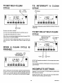
TO SET SELF-CLEAN
CYCLE
TO INTERRUPT
CYCLE
A CLEAN
TURN
) PUSH
1/2 TURN
I_.
TIMER
CLOCK STOP
TIME
CLEAN
COOt{
TIME
BROIL
BAKE
m ,o=g
II:-J
-_1Lt_.
TIMER CLOCK STOP
TIME
mm
_lnllm
CLEAN
mlnm
COOK
TIME
m
BROIL
BAKE
mllmnlm
Then follow instructions under WHEN A CLEAN CYCLE IS
FINISHED.
Imm_mllmmmllm
PUSH
Be sure oven door is closed.
TO SET DELAY SELF-CLEAN
CYCLE
The door locks automatically after the controls are set.
The self-clean cycle lasts 3-1/2 hours.
When the oven reaches locking temperature the word LOCK
will be shown in the ERC display.
TURN TO SET OVEN
TURN OFF TIME
ITURN 1/2
TURN
You can push STOP TIME BUTTON to lind out when the
cycle will end. Push CLEAN BUTTON to return to count
down.
I..
WHEN A CLEAN
FINISHED
SET
CYCLE
WAIT UNTIL
('
LOCK GOES OUT"
(20-30 minutes)
IS
I.-l i-I ....
P,_3U
TIMER
CLOCK STOP
m
n
COOK
TIME CLEAN TIME BROIL BANE
iml
m
m
=ram m
)
PUSH
I
PUSH
STOP TIM E must be more than 3-1/2 hours later than cu rrent
time of day.
;ANCEL
TIMER
CLOOK STOP
TIME
CLEAN
COCK
TIME
BROIL
You can press and hold CLEAN button to find out when clean
cycle will start.
BAKE
mm_m_mml
INCOMPLETE
Alter a clean cycle, the oven door cannot be opened unless
the word LOCK is olf in the ERC display and the oven has
cooled. If you cannot open the door immediately after the
word LOCK goes oft, wait about one minute and try again.
SETTINGS
Attention Tone will sound if CLEAN button is pushed and
SET knob is not turned.
Display will show "door" if the oven door is not fully closed.
Close the door and the cycle will resume.
20
CSCL03-3
Cleaning Tips
On the following pages, all removable parts on your range are shown. Refer to those pages when cleaning.
Warm water, a mild detergent and a soft cloth are safe to use on all cleanable parts of your range. All purpose cleaners, such
as Fantastik®, can also be used (except on cooktop burner; see below). Do not use metal scouring pads, except where recommended.
Range cooktop finishes will be either porcelain enamel or brushed chrome. Porcelain enamel looks like a painted surface.
Brushed chrome has a metallic appearance.
REMARKS
PART
CLEANING MATERIALS
Control panel knobs
Detergent, warm water, soft cloth
Do not use abrasive cleaners. Knobs pull off
for easier cleaning.
Porcelainenameled cooktop,
chrome drip bowls (some
models), area undercooktop,
burner grates
Detergent, warm water, plastic or
nylon scouring pad
Clean after each spillover. Rub chrome bowls
(some models) gentlywith scouringpad. Soak
stubborn soil. Bowls can be removed during
burner use to keep clean and to avoid discoloration caused by excessive heat.
Cooktop burners
Detergent, warm water, plastic or
nylon scouring pad or boil in Dip-it®
solution to remove stubborn soil
Do not use all-purpose cleaners, ammonia,
powder cleansers or oven cleaners. Such
Pi_roducts
can scratch or discolor the burners.
o use Dip-it@ solution, remove burners and
boil for 20 minutes in 2 T. Dip-it® granules per
_luart of water. Boil with burner head down.
inse thoroughly, drain and completely dry
burners in a 200°F oven for 1/2 hour. After
cleaning or a spillover, light the burners and
make sure that no ports are clogged (see next
page).
Brushed chrome cooktop
Detergent, warm water, soft cloth or
a chrome cleaner or Sears Cooktop
Cleaning Creme
Do not scour chrome tops. Stubborn stains
may be removed by using Espree Magwheel
Cleaner_orTurtle Wax Polishing Compound®.
To remove finger prints on brushed chrome,
apply a little baby oil with a paper towel. Rub
in the direction of the brush marks. Armor All
Protectant® can also be used (after cleaning).
Be sure to clean spills of acidic foods quickly.
Vinegar spills can permanently stain chrome.
Ifcleaning methods described above prove ineffective, baked-on food residue or stains
on chrome cooktops can be removed by using pad type oven cleaners. Use extreme
caution. Oven cleaners are caustic and will damage painted or aluminum surfaces,
such as range sides, backguard or control panel. Do not use spray type oven cleaners.
Overspray will damage nea .€oypainted surfaces and heating elements. Use several
layers of newspaper and mask=ngtape to cover surfaces such as the backguard, control
panel, range sides, countertops, etc. Remove cooktop elements (except solid disk
elements), burner bowls, grates, etc. Apply the pad type oven cleaner evenly to the
entire top surface. The ent=retop must be cleaned to keep the finish consistent _ncolor.
Use extreme caution to prevent the oven cleaner from coming in contact with any other
surface. Let the cleaner remain on the top for 20-30 minutes. Rinse the top well to
remove every trace of oven cleaner. Dry the top and apply Armor All Protectant® to
protect the finish.
Glass oven door/window
Glass cleaner and paper towels
Remove stubborn soil with paste of baking
soda andwater. Do not use abrasive cleaners.
Rinse thoroughly.
Self-cleaning oven finish
Detergent, warm water, scouring pad
or soap-filled steel wool pad
Rinse well after cleaning. Cleaning inside the
oven need only be done as an optional touchup between self-clean cycles. See the selfcleaning oven section in this manual for more
information.
Oven door gasket
Hydrogen peroxide
Soak with hydrogen peroxide, using a sponge.
Frequent soaking helps prevent soil buildup.
Do not rub. See self-cleaning section for more
information.
21
GCCH05-2
Cleaning Tips (continued...)
Refer to the removable parts section when cleaning your oven.
Warm water, a mild detergent and a soft cloth are safe to use on all cleanable parts of your range. All-purpose cleaners, such
as Fantastik®, can be used.
Do not use metal scouring pads, except where recommended.
PART
CLEANING MATERIALS
REMARKS
Oven racks (and removable
guides on some models)
Detergent, warm water, scouring
pad or soap-filled steel wool pad
Remove from oven to clean. Rinse
thoroughly.
Broiler pan and grid
Detergent, warm water, soap-filled
scouring pad, commercial
oven
cleaner (pan only)
Remove soiled pan from oven to cool. Drain
fat or drippings. Fill pan with warm water.
Sprinkle grid with detergent and cover with
damp cloth or paper towels. Let pan and gdd
soak for a few minutes. Rinse or scour as
needed. Dry well. Grid and pan may be
washed in a dishwasher.
REPLACING THE OVEN LIGHT
(self-cleaning
models)
Do not touch hot oven bulb. Do not touch oven bulb with
wet hands. Do not wipe oven light area with wet cloth.
Unplug or disconnect the electrical supply to range
before removing.
GLASS
Never touch the electrically live collar on the bulb when
replacing it.
SOCKET _
GASKET
Electrical power must be shut off If you have to replace
a broken bulb.
1. Remove the three screws and lift off the glass retainer,
glass cover and gasket.
BULB
GLASS
2. Replace the bulb with a 40 watt appliance bulb. An
appliance bulb is smaller than a standard 40 watt
household bulb.
COLLAR
BULB
_
COVER
3. Replace the gasket, glass cover and glass retainer.
Tighten screws securely.
22
GCCH25
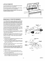
LIFT-UP COOKTOP
To raise lhe cooktop so the area underneath can be cleaned,
grasp the cooktop at the front and lift up.
The range has a support to hold the cooktop while cleaning.
Raise the support as shown in the illustration.
Porcelain enamel can chip if dropped.
enameled cooktops carefully.
REMOVABLE
COOKTOP
Handle porcelain
BURNERS
The cooktop burners on your range may be removed for
cleaning Be sure all cooktop knobs are turned to OFF
and burners are cool, then remove or raise the cooktop.
Some models have two types of burners. One type of burner
has a solid top and is used at the two rear cooktop positions
and at the left front cooktop position of some models.
GAS VALVE
ORIFICE
BURNER
SUPPORT
The second type of burner is cone-shaped and has a circular
opening through the center of the burner head. This 12,000
13TUburner is used at the right front cooktop position or at
both front cooktop positions of some models.
De not try to use the burners in any other position. Damage
to your range may result if the smaller burners are used in the
12,000 BTU burner positions.
AIR
SHUTTEF
If shipping screws were not removed from the burner when
the range was installed, do so now (see your Installation
Guide for instructions). These screws may be discarded.
TAB
Fig. A.
To remove burners:
1. Grasp the burner head and tilt it to release the two tabs
from the burner support (A in Fig. A).
2. Lift the end of the burner assembly, then pull away from
the front of the range to free the air shutter from the gas
valve orifice (B in Fig. A).
BURNER
PILOT
LIGHTER
Check lighter and burner ports (Fig. B). If they are clogged,
use a wire or needle to clear them.
PORTS
OR
PORTS
See the Cleaning Tips Chart in this manual. Be careful not
to disturb the air shutter setting while cleaning. If you
need to readjust the air shutter, see the Installation section.
FLASH
TUBE
To replace burners:
Fig. B
1. Slip the air shutter over the gas valve orilice (Fig A)
2. Lower the burner assembly and hook the tab in the slots
in the burner suppod (Fig. A)
3. Be sure bolh tabs are in their slots, that the burner sits
level and straight and that the flash tube forms a straight
line from the igniler to the burner (Fig. B)
23
GMNT25-2
REMOVABLE
OVEN DOOR
To remove:
STOP (BROIL) POSITION
1. Open the doer to the stop position {see illustration).
2. Grasp the door at each side and lift up and off the hinges.
/
NOTE: When the door is removed and hinge arms are at
stop position, do not bump or try to move the hinge arms.
The hinges could snap back causing an injury to the
hands or damage to the porcelain on the front of the
range. Cover the hinges with toweling or empty towel
rolls while working in the oven area,
To replace:
1. Hold the door over the hinges with the slots at the bottom
edge of the door lined upwith the hinges. The hinge arms
must still be in the stop position.
HINGE
2. Slide the door down onto the hinges as tar as it will go and
close the door.
REMOVABLE
OVEN RACKS
Be careful not to scratch the oven finish when installing
or removing oven racks.
To install:
1. Set the raised back edge of the rack on a pair of rack
guides.
2. Push the rack in until you reach the bump in the rack
guide, then lift the front of the rack a bit and push the rack
all the way in.
TO remove:
1. Pull the oven rack out, then up.
Some models have one standard oven rack and one folding
oven rack.
The folding rack can be conveniently stored away when not
in use.
REMOVABLE
OVEN BOTTOM
The oven bottom may be removed for cleaning heavy spillovers or to reach the oven burner.
Be careful not to scratch the oven finish when removing
or replacing the oven bottom.
To remove:
1. Slide the tab at the center front of the oven bottom to the
left.
2. Lift the oven bottom up and out.
To replace:
1. Slip the oven bottom into the oven so the tabs in the rear
of the oven bottom fit into the slots in the oven back.
2. Lower the tront of the oven bottom into place and slide the
tab at the front right to lock the oven bottom into place.
24
GMNT06 1
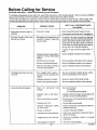
Before Calling for Service
Save time and money -- Check this list before you call for service.
To eliminate unnecessary service calls, first, read all the instructionsin this manual carefully. Then, if you have a problem,
always check this list of common problems and possible solutions before you call for service.
If you do have a problem you cannot fix yourself, call your nearest Store or Service Center for help. When calling, have
this manual handy with the model number, serial number and purchase date filled in on the space on the front cover.
PROBLEM
DON'T CALL FOR SERVICE UNTIL
YOU CHECK
POSSIBLE CAUSE
• Check household circuit breaker or fuse.
• Range does not work; totally inoperative
• No power to range
• Cooktop burners and oven
burners do not work
• Gas suppry not connected or not
turned on; if using L.P. gas, tank
may be empty
• Check power cord to be sure it is plugged in.
To check if the gas is turned on, light the
cooktop burners with a match by following the
steps in the ignition section of this manual. If
the burners do not light, check the shut-off
valve below the lift-up cooktop (see valve to
be sure that it is in the open position).
If using L.P. gas; is there any gas in the L.P.
tank?
• Cooktop burner does not work
oven OK
• Foods do not bake properly
• Range not properly grounded or
polarized; this can affect spark
ignition
Check installation section in this manual.
• Controls not set correctly
Check operating instructions in this manual.
• Burners not adjusted properly
See the installation section in this manual.
• Shut-off valve below cooktop is
not in the open position
Check installation section in this manual.
• Soil clogging holes (pods) in
burner or burner assembly misaligned
• See the removable cooktop burner section
and the cleaning tips in this manual.
• Improper operation of control
• Be sure to push knob in while turning.
• Burners not adjusted properly
• See the installation section in this manual.
• Oven not
enough
• Improper
ment
preheated
long
rack or pan place-
• Be sure to preheat:
15 minutes
or until preheat tone signals
• Maintain uniform air space around pans and
utensils; see oven cooking section.
• Oven vent blocked or covered
• Be sure oven vent (in panel behind cooktop)
is not blocked.
• Improper use of foil
• Foil use not recommended.
• Improper temperature
for utensil used
setting
• Reduce temperature 25 degrees for glass or
dull/darkened pans.
• Recipe not followed
• Is recipe tested and reliable?
• Improper thermostat calibration
• Check oven temperature adjustment procedures (next page).
• Range and oven rack not level
• Check the installation
instructions.
• Using improper eookware
25
• See oven cooking section.
section for leveling
GSERO2-3
Before Calling for Service
PROBLEM
Foods do not broil
properly
POSSIBLE
CAUSE
DON'T CALL FOR SERVICE
UNTIL YOU CHECK
Improper rack position
Check broil pan placement; see Broiling
section.
Do not preheat when broiling.
Use broiler pan and grid supplied with range.
Check broiling chart.
Oven preheated
Improper ulensil used
Improper broiling time
Oven smokes
Dirty oven
Broiler pan full of grease left in
oven
Check for heavy spillover.
Clean pan and grid after each use.
Oven light or work
light does not work
(it equipped)
Light switch in oft position
Light bulb or fluorescent light
starter burned out
Check switch setting.
Check or replace light bulb or fluorescent
light starter; see use and care instructions.
Oven does not clean
or poor cleaning
results (Self-clean
models only)
Controls not set properly
Clean cycle interrupted too
soon
Oven too dirty
Check self-clean instructions.
Heavily soiled ovens require a 3 1/2 hr. clean
cycle.
Heavy spillovers should be removed before
setting clean cycle.
Oven door will not
unlock (Self-clean
models only)
Clean cycle not complete
Tone does not sound
Tone has been eliminated by
pushing and holding CANCEL
button
Push and hold CANCEL button to activate
tone.
Heavily soiled or
stained chrome
cooktop cannot be
satisfactorily cleaned
Spills were not wiped up
promptly
See the instructions, under Cleaning Tips,
for cleaning chrome cooktops with oven
cleaner. This procedure requires extreme
caution. Read instructionscarefully.
ADJUSTING
OVEN TEMPERATURE
• Oven must cool below lock temperature
(20 to 30 minutes after clean cycle is
complete).
3. Quickly (within two seconds, before the BAKE Function
energizes) push and hold the BAKE button.
The temperature in your new oven has been set correctly at
the factory, so be sure to follow the recipe temperatures and
times the first few times you bake in your new oven.
The display will change to the amount of degrees difference between the original factory temperatu re setting and
the current temperature setting. If the oven has the original factory setting, the display will read go.
If you think the oven should be hotter or cooler, you can adjust
it yourself. To decide how much to change the temperature,
set the oven temperature 25°F higher or lower than the
temperature in your recipe, then bake. The results of this
'lest" should give you an idea of how much the temperature
should be changed.
4. The temperature can be adjusted up to 35°F hotter or
cooler (in 5°F steps), by turning the SET knob. A minus
sign (-) before the number means that the oven will be
cooler by displayed amount of degrees.
5. When you have made the desired adjustment, push the
CLOCK button to go back to the time of day display or use
your oven as you would normally.
To Adjust Oven Temperature:
1. Push the BAKE button.
2. Select a temperature between 500°F and 550°F with the
SET knob.
Note: The self-clean temperature will not be changed by the
adjustments described above.
26
GSERO84
HOW TO ORDER REPAIR PARTS
All paris listed herein may be ordered from any Sears, Roebuck
and Company retail or catalog store.
WHEN ORDERING
REPAIR PARTS, ALWAYS
GIVE THE
FOLLOWING INFORMATION:
1. PART NUMBER
4. COLOR OF ITEM
2. PART DESCRIPTION
5. NAME OF ITEM:
3. MODEL NUMBER
Gas Range
The Model Number will be found on a tag attached to the Range
Front Frame. To locate tag, open the Storage Drawer. Always
mention the Model Number when requesting service or repair
paris for your Range.
II the parls you need are not stocked locally, your order will be
electronically transmitted to a Sears Repair Parts Distribution
Center for expedited handling.
Repair Paris are listed on the following pages,
27
GNOT03
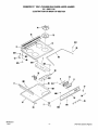
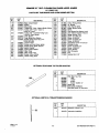
KENMORE 30"
SELF-CLEANING
GAS RANGE-MODEL
911.3651190
ILLUSTRATION
NUMBER
FOR MAIN TOP SECTION
76
\
801
/
_ 86
2/
9O
601
I1_
61
805
63
SMTOP0339-1
1-9-91
-1-
(For Parts List See Page 2)
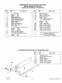
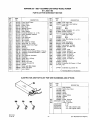
KENMORE 30" SELF-CLEANING
GAS RANGE
MODEL NUMBER 911.3651190
PARTS LIST FOR MAIN TOP SECTION
KEY
NO.
PART
NO.
2
7
8
11
16
17
21
25
29
3O
32:
5!
52
61
63
............
330344
330345
343802
343008
341638
342136
343084
334649
337484
336367
339197
340431
............
347299
347300
347301
343071
339463
............
330558
337674
DESCRIPTION
KEY
NO.
71
73
74
76
86
90
91
End Cap
Left
Right
Fan Duct
Clock Stiffener
Body Side Extension
Clock/Oven Control
Clock Lens Asm
Switch
Fan Bracket
Gas Valve Knobs
Clock Knob
Fan
Main Top Asm w/Hinge Bracket
White
Almond
Chrome
Manifold Panel Asm
Burner Box Bottom
Burner Box Bottom Stiffener
Left
Right
ILLUSTRATION
93!
95
801
8O5
8O6
831
841
874
PART
NO.
DESCRIPTION
346545
336363
330242
345689
337251
336079
............
334844
334843
337487
335161
34695O
326974
316849
327621
78153
286628
Insulation
Aeration Pan
Top Burner Grate
Vent Cover
Clamp
Main Top Support Rod
Main Top Hinge
Left
Right
Wire Cover
Hinge Bracket
Screw 10-16x7/16"
Screw 10ABxl/2"
Screw 10-32x 1/2"
Screw 6-20x3/8"
Screw 6-32x5/16"
Screw 10-32x5/16"
346435
Owners Manual (Includes Installation
Instructions and Parts List)
Mini Manual w/Wire Diagram
Parts Not Shown On Illustration
347857
AND PARTS LIST FOR BACKSPLASH
KEY
NO.
2
7
11
36
45
801
808
819
45
PART
NO.
330339
342125
3346O2
337503
342722
346950
321162
337857
DESCRIPTION
End Cap
Backsplash Supporl
Filler
Backsplash
Spacer
Screw 10-16x7/16"
Screw 10-32x3/4"
Screw 6-20x5/16"
808
i!
"\_-----801
AALG0060-5
10-18 91
-2-
(For Illustration
See Page 1)
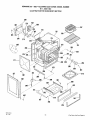
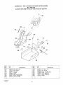
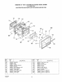
KENMORE 30"
SELF-CLEANING
GAS RANGE-MODEL
NUMBER
911.3651190
ILLUSTRATION
FOR OVEN BODY SECTION
220
233
601
_936
235
215
/
801
234
231
216
256
258
"
259
861
221
_--210
801
807
\,_/
267
293
226
SBDYL0368
lo-3-9o
-3-
(For
Parts
List
See
Page
4)
KENMORE 30"
SELF-CLEANING
GAS RANGE-MODEL
NUMBER
911.3651190
PARTS LIST FOR OVEN BODY SECTION
KEY
NO.
PART
NO.
140
201
340356
337039
336341
346115
338189
338159
335231
328959
331144
327781
345654
327809
343851
346204
341640
340377
343952
336510
332205
329147
329146
335815
343768
330166
326069
346003
326297
344119
334300
344111
339665
229371
202 1
203
204
208
210
211
212
214
215
216
219
220
221
222
224
225
226
231
232
233
234
235
241
246
247
268
253
256
257
258
KEY
NO.
DESCRIPTION
Front Panel Frame
Oven Body
Front Frame
Main Back
Storage Drawer
Heat Baffle
Oven Bottom
Insulation Retainer (Lt. or Rt,)
Lower Insulation Retainer
Flue Box
Flue Deflector
Wire Shield
Wire Shield
Flue Deflector Shield
Body Side (Lt. or Rt.)
Storage Door Front Panel
Spacer
Insulation
Storage Door Handle
Insulation-Oven Top and Sides (1 Piece)
Insulation-Oven Back/Bottom ( 1 Piece)
Insulation
Flue Deflector Insulation
Insulation
Oven Rack (2 Req)
Broiler Pan
Broiler Pan Grid
Stability Bracket Kit
Sensor
Oven Light Bulb Holder
Oven Light Bulb
Lens Gasket
259
260
262
266
267
268
281
286
291
292
293
296
801
804
805
807
810
811
830
861
880!
935
9361
979
995
*
PART
NO.
DESCRIPTION
114989
229372
............
330340
330341
346477
317656
344119
............
332346
332345
342300
304835
281913
281914
343627
346950
120855
326974
314124
102428
102563
102430
69364
341627
21067
324257
312605
341134
Oven Light Lens
Oven Light Lens Retainer
Side Trim
Left
Right
Base w/Levelers (Lt. or Rt.)
Drawer Support
Stability Bracket Kit
Oven Door Hinge
Left
Right
Oven Door Spring (Lt. or Rt.)
Cover
Rear Slide Block
Front Slide Block
Leg Leveler (4 Req)
Screw 10-16x7/16"
Screw
Screw IOAB
Screw 8ABx5/8"
Screw 10-32x17/32"
Screw 8-32x3/8"
Screw 10-32xl/2"
Screw IOABx3/4"
Screw 10-32x5/8"
Washer
Bushing
Expansion Nut Spacer (4 Req)
Nut
344491
Extended Leg Leveler Kit
Part Not Shown on Illustration
ILLUSTRATION
560
570
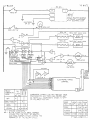
AND PARTS LIST FOR WIRE HARNESSES AND OPTIONS
KEY
NO.
PART
NO,
551
............
341866
347194
342445
333274
341291
341780
346123
238387
STD374251
............
STD374180
STD374250
STD374120
STD374132
560
57O
58O
580
DESCRIPTION
Wire Harness
Switch-Gas Valve
Main
igniter
Sensor
Spark Module
Ground
ERC
Eyelet Terminal
Flag Terminal
Faston Terminal
3/16"
1/4"
.110-.020
(Switch Lead)
.110-.032
(Igniter Lead)
SBDYL0369
10-03-90
-4-
(For Illustration
See Page 3)
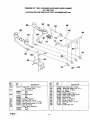
KENMORE 30"
ILLUSTRATION
SELF-CLEANING
GAS RANGE-MODEL
911,3651190
NUMBER
AND PARTS LIST FOR DOOR LOCK SECTION
801
/
_'
171
161
173
946
183
166
I__
KEY
NO.
151
161
166
171
173
182
183
184
SLOCK0108
10-4-90
PART
NO.
336910
334078
337485
329171
337834
343239
337771
337937
KEY
NO.
DESCRIPTION
Lock Motor Asm
Micro Switch
Lock Box
Insulator
Spring
Door Switch Bracket
Switch Actuator Pin
Door Lock Plate
185
195
801
810
817
828
946
-5-
PART
NO.
337971
337933
346950
102428
338318
97217
335039
DESCRIPTION
Lock Lever Asm
Lock Spring
Screw 10-16x7/16"
Screw 10-32x17/32"
Screw 4ABx3/4"
Screw 8-32x3/8"
Washer
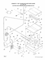
KENMORE 30"
ILLUSTRATION
SELF-CLEANING GAS RANGE-MODEL
911.3651190
AND PARTS LIST FOR TOP BURNER SECTION
302
J
NUMBER
986
3O8
838
366
4OO
/
307
/
352
/
828<
I
KEY
NO.
PART
NO.
302
331107
307
............
342545
342543
............
342544
342546
324528
336369
333508
312453
326830
............
342819
342820
308
312
314
314
317
319
322
SBRNUOOO4-1
11 - 1 O-SO
KEY
NO.
DESCRIPTION
Tubing 318" (Shut-Off Valve
to Control Valve)
Top Front Burner
Left
Right
Top Rear Burner
Left
Right
Pressure Regulator
Gas Valve (Rt. Front)
Gas Valve (Lt. Frt., Lt./Rt. Rear)
Spark Igniter Bracket (Lt. or Rt.)
Shut-Off Valve
Spark Igniter Electrode
Rear
Front
323
i334
352
353
366
366
366
400
801
828
838
839
986
-6-
PART
NO.
310253
330358
342613
342615
313563
311692
304241
330348
346950
97217
311455
301911
113384
DESCRIPTION
Gas Valve Switch (4 Req)
Top Burner Support (Rt. or Lt.)
Air Shutter (3 Req)
Air Shutter
Rubber Gasket-Valve
Rubber Gasket-Valve Screw
Safety Valve Gasket
Manifold Pipe
Screw 10-16x7/16"
Screw 8-32x3/8"
Mounting Screw 1/4-20
Screw
Inverted Nut 3/8"
314
KENMORE 30"
SELF-CLEANING
GAS RANGE-MODEL
NUMBER
911.3651190
ILLUSTRATION
FOR BROILER AND OVEN BURNER SECTION
311
/
04O
554
374
316
801'
839
\
/
374_'_-828
/861
303
348
82O
949
/
839
819
/
/
318
801
347
320
/'
31
310
-391
SBRNLOT17
10-4-90
(For Parts List See Page 8)
KENMORE 30"
SELF-CLEANING
GAS RANGE-MODEL
NUMBER
911.3651190
PARTS LIST FOR BROILER AND OVEN BURNER SECTION
KEY
NO.
PART
NO.
337633
334955
232150
341647
331107
342226
333746
327775
327806
306267
337263
327804
311689
320990
345365
345366
331992
328473
KEY
NO.
DESCRIPTION
348
353
373
374
374
380
391
554
801
819
820
828
839
852
856
861
933
940
949
966
Relay Circuit Board
Spacer
Disconnect
Tubing 318"-Cont. Valve to Broiler Orifice
Tubing 3/8"-Cont.
Valve to
Shut-Off Valve
Tubing 3/8" w/Orifice FRting-Cont.
Valve to Oven Burner
Oven Burner
Oven Burner Box Bottom
Broiler Burner-lnc's Key 374839-353-828
Control Valve
Broiler and Oven Burner Igniter
Broiler Burner Igniter Bracket
Igniter Bracket
Spark Igniter Module
Wire Cover
Wire Cover Front
Broiler Orifice Fitting
Orifice Fitting Plate
OPTIONAL
PART
NO.
331864
312988
335196
327807
328660
328479
329279
235822
346950
329382
343720
97217
312989
328584
105771
69364
333674
103595
106767
113384
PART
NO.
290
334389
3353881
335389
326974
69365
335639
VERTICAL
DESCRIPTION
Filler Main Top Trim
.500"
1.562"
2.062"
Screw lOABxl/2"
Speed Nut
Instructions Installation
Parts Not Shown Onlllustration
TRIM EXTENSION 8068690
KEY
NO.
-----262
SBRi_.O118-2
1-31-91
Orifice Fitting Shield
Air Shutter
Oven Burner Baffle
Broiler Burner Baffle
Baffle
Oven Burner Box Bottom Latch
Oven Orifice Insulation Retainer
Range Service Cord
Screw 10-16x7/16"
Screw 6-32x3/8"
Screw 10-32x7/16"
Screw 8-32x3/8"
Adjustment Screw-Air Shutter
Shoulder Screw
Screw 10-32x7/16"
Screw IOABx3/4"
Spring Washer
Wire Connector
Clip
Inverted Nut 3/8"
REAR MAIN 'TOP FILLER 8028790
KEY
NO.
OPTIONAL
DESCRIPTION
-8-
PART
NO.
DESCRIPTION
262
331512
Extension-Vertical Trim
•
331678
Instruction Installation
(For Illustration See Page 7)
KENMORE 30"
SELF-CLEANING
GAS RANGE-MODEL
NUMBER
911.3651190
ILLUSTRATION
131
124
AND PARTS LIST FOR OVEN DOOR SECTION
132
/
812
818 117
/
82O
146
143
112
114
136
140
KEY I
NO.
111 [
112 I
113
114
116
117
121
122
, 123
124
50VDRO248
10-8-90
PART
NO.
335782
331555
344427
338326
345646
328615
341060
332067
326088
338108
342332
KEY
NO.
r)ESCRfPTION
131
132
133
136:
140
143
146
147
8121
818
820
!Insulation
Plug
I Lining
Insulation
Retainer
Retainer
Glass Mount ng Plate
Glass Retainer
Outer Glass
intermediate
Glass
! Center Glass
Inner Glass
-9-
PART
NO.
302935
292244
335945
332452
337765
333015
107158
333014
331704
_R9965
343720
DESCRIPTION
Inner Glass Seal
Gasket
Felt Washer
Handle
Frame
Glass Spacer
Handle Spacer
Washer
Screw 10-32x5/8"
Screw 10-32x3/4"
Screw 10-32x7/16"
L "BLACK
20+
'N" WHITE
M-Q.
w
VALVE
SW
t
•
, MODULE
I SPK _GN
1
I V.ODULE F:"OLAR?'Y REVERSED
i TO PREVENT INTERFERENCE
j V _1 E N ELECTRON;C CLOCK
UGHT
DOOR
BROIL '"'
i..aN
BROIL CONT VALVE 1.22_q.
BAKE ION
BAKE CONT VALVE !.22Z'L
SW
I
CN
BK
120-150 m
RLI
LOCK SW
"2
LOCK MOTOR
FAN MOTOR
,_'_--'l 0VEN
:_
I TEMP
:_
ISENSOR
"1
I I[OOZ',_
A
A _TB°F
ELECTRONIC
RANGE
CONTROL
.--j@ g2
RELAY
CONTACTS
MADE
OFF
RLI
RI
C
LOCK
NC NO
F
÷
BAKE/TIMEE
BROIL
CLEAN
- CYCLING
_
COMPONENT SYMBOLS DO NOT REFLECT TRUE
CONFIGURATION, ALL FEED LINE COLORS ARE
AS NOTED. ALL COMPONENTS SHOWN IN 'OFF'
OR "RELAXED"POSITrON.
i
DOOR
LOCK
POS',TION SW_!
LOCK
SW_2
DOOR
SW
OPEN
C-NC
C-NC
CLOSED
C-NC
C-NO
C-NO
g-NO
_ i*
CONTACTS.
CLEAN
CYCLE
BROIL BURNER
CYCLES
FOR
THE FIRS T 30 MINUTES
AND BAKE
BURNER
CYCLES
DURING
THE
REMAINDER
OF THE CLEAN
CYCLE.
• _ - IN THE
LOCKED
C-NO
PT.NO.
LBW074-1
KENMORE GAS RANGE WARRANTY
FULL ONE YEAR WARRANTY ON THE FUNCTIONING
EXCEPT GLASS PARTS
If, within one year from the date of installation, any part, other than a glass part,
fails to function properly due to a detect in material or workmanship, Sears will
repair or replace it, free of charge.
Dear Customer:
Our constant efforts are directed toward making sure
your new Kenmore Range
wilt arrive at your home in
perfect condition and will give
you proper performance.
As
pad of these efforts, we feel
it is our responsibility to provide you with this warranty
for your range.
OF ALL PARTS
FULL 30-DAY WARRANTY ON GLASS PARTS AND FINISH OF PORCELAIN ENAMELs PAINTED OR BRIGHT METAL
FINISHED PARTS
If, within 30 days from the date of installation, any glass part is detective in
material or workmanship, Sears will replace the part, free of charge.
FULL 90..DAY WARRANTY ON MECHANICAL
ADJUSTMENTS
For 90 days from the date of installation, Sears will provide, free of charge, any
mechanical adjustments necessary for proper operation of the range, except for
normal maintenance.
WARRANTY SERVICE IS AVAILABLE BY CONTACTING THE NEAREST
SEARS SERVICE CENTER/DEPARTMENT IN THE UNITED STATES
This warranty applies only while this product is in use in the United States. This
warranty gives you specific legal rights, and you may also have other rights
which vary from state to state.
SEARS, ROEBUCK and CO.
Dept. 731 CR-W
Sears Tower
Chicago, IL 60684
WE SERVICE WHAT WE SELL
"We Service What We Sell" is our assurance to you that you can depend on Sears for service because Sears service
is nationwide.
Your Kenmore Range has added value when you consider that Sears has a service unit near you staffed by Sears
trained technicians.., professional technicians specifically trained on Sears appliances, having the parts, tools and
equipment to ensure that we meet our pledge to you -- "We Service What We Sell!"
TO FURTHER ADD TO THE VALUE OF YOUR RANGE, BUY A SEARS MAINTENANCE AGREEMENT.
Years of Ownership
Kenmore Ranges are designed, manufactured and
tested for years of dependable operation. Yet, any
modern appliance may require service from time to
time. The Sears warranty plus the Sears Mainte nance
Agreement provides protection from unexpected repair
bills and assures you of enjoying maximum range
efficiency.
Here's a comparative warranty and Maintenance
Agreement chart showing you the benefits of a Sears
Range Maintenance Agreement.
1
2
Coverage
1 st Year
2nd Year
3rd Year
MA
MA
Warr °,yMA
MA
Replacement of Oe fectJve
Parts othe, than Porcelain
or Glass
W
90 Days
Full
Mechanical
Adjustment
W
3
Porcelain and Glass Parts
30 Days
Full
Warranty
MA
MA
MA
MA
MA - Maintenance
Agreement
W
4
Annual Preventive Maintenance Check at your request
W - Warranty
W
CONTACT YOUR SEARS SALESPERSON OR LOCAL SEARS SERVICE
CENTER TODAY AND PURCHASE A SEARS MAINTENANCE AGREEMENT.
Ken m ore + America's
Best Selling Appliance Brand
Sold by SEARS, ROEBUCK AND CO., Chicago, IL 60684
I