1
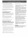
INSTALLATION
AND SERVICE MUST BE PERFORMED BY
A QUAUHED INSTALLER.
IMPORTANT: SAVE FOR LOCAL ELECTRICAL INSPECTOR'S USE.
READ AND SAVE THESE INSTRUCTIONS FOR FUTURE REFERENCE.
property
[f the information
in this manual is not followed
damage, personal injury or death.
exactly, a fire or explosion
may result causing
FOR YOUR SAFETY:
--
Do not store or use gasoline or other flammabJe
appliance.
-- WHAT TO DO tF YOU SMELL GAS:
vapors and liquids
in the vMnity
of this or any other
*
Do not try to light any appliance.
Do not touch any e[ectrka[ switch; do not use any phone in your building,
Immediately call your gas supplier from a neighbor's phone. Follow the gas supp[ier's
,,
--
ff you cannot reach your gas supplier, ca[[ the fire department.
Installation and servke must be performed by a qualified installer,
instructions.
servke agency or the gas supplier.
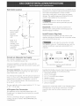
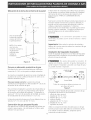
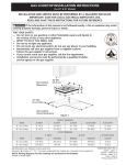
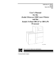
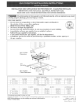
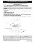
For Standard
Installation:
* 30" (76.2 cm) rain. for
unprotected cabinet and
24" (61 cm) rain. for cabinet
with protected bottom surface.
Gas Cooktop Dimensions
/A
X4" (!0.2 cm x 10.2 cm)
opening to route gas supply.
Gas Cooktop Cutout
Dimensions
2"(5.1 cm) Dia.
Opening to route -power cabFe
71/4
(18.4 cm)
F
G
Do not slide unit into cabinet cutout,
Protruding screws on the bottom of ur it
may damage the bottom front finish.
Figure 1
**Note: D & E are critical to the proper
installation of the cooktop. D reflects the
finished dimension. Due to the variation in
countertop materials, it is recommended to first
undercut this dimension, and then adjust it
upon installation of the cooktop.
All dimensions are stated in inches and (cm).
318201459
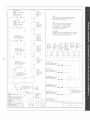
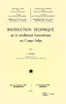
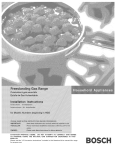
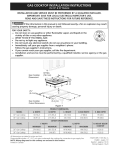
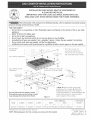
NOTE: Wiring diagrams for this cooktop
English - pages 1o10
Espar_ol - Diginas
11-19
Wiring Diagram page - 20
are enclosed in this booklet
(0407)
Rev A
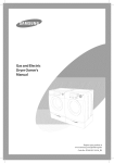
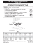
* 30" (76.2 cm) rain, for
unprotected cabinet and
24" (6! cm) rain, for cabinet
with protected bottom surface.
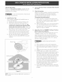
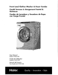
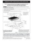
For Installation with the optional Stainless Steel Backsplash,
Gas Cooktop Dimensions
2" (5.1 cm)
9" (22.9cm)
Optional
Stainless Steel
Backsplash
***Note: Applies only in case
of countertop backwall.
4"X 4" (10,2 cmx 10,2 cm)
pening to route gas supply.
2" (5,1 cm)
opening to route
power cable.
H
7Y4"(18.4 cm)
351/_
cm/
Gas Cooktop Cutout Dimensicns
Do not sJide unit into cabinet
cutout,
Protruding
screws on the bottom
of unit
may damage the bottom
front finish.
MODiE
I
36 (91,4)
I
2
A:EENGTN
I BwliTH I cDEPTH
I
l
Figure
I
357/8(91'I)
I
I
25(63,5)
I 73A(19'7)
All dimensions are stated in inches and (cm).
I
**Note: D & E are critical to the proper
installation of the cooktop. D reflects the
finished dimension. Due to the variation in
countertop materials, it is recommended to first
undercut this dimension, and then adjust it
upon installation of the cooktop.
I
WIDTH
D** I E**
I FI
G
CuTOuTDIMENSIONS
35W_6(91.3)
I
I
BELOW
I
BA_KWA[E
ICOOKTOPI
CUTOUT
H:DEPTH JiCOuNTERToP
3S3/_6(gg.4)I22(SS.g)IIVs(2.g)Max.
I 7Y2(19,1)
I
35m/_6(9I'3)
important
1.
2.
3.
4.
5.
Notes to the installer
Read all instructions contained in these installation
instructions before installing the cooktop.
Remove all packing material before connecting the
electrical supply to the cooktop.
Observe all governing codes and ordinances.
Be sure to leave these instructions with the consumer.
Note: For operation at 2000 ft. elevations above see
level, appliance rating shall be reduced by 4 percent
for each additional I000 ft.
Important
Note to the Consumer
Keep these instructions with your Use and Care Guide for
future reference.
Depth
Adjustment
Filmer Kit #903051o9010
This cooktop is designed to replace existing unit. If the
depth of your countertop opening is bigger than 7_/4" (18.4
cm) and less than 8Y2" (21.6 cm) you can order a free filler
kit #903051-9010 by calling Sears Parts & Repair Center at
1-800-4-MY-HOME®.
Optional
Item Available:
• A 9" (22.9cm) Stainless Steel Backsplash
Kit #903048-9010
This kit can be ordered for purchase through Sears Parts
& Repair Center at 1-800-4-MY-HOME®.
IMPORTANT
INSTRU
SAFETY
S
Installation of this cooktop must conform with local (:odes
or, in the absence of local codes, with the National Fuel
Gas Code ANSI Z223.1/NFPA54--1atest edition in the
United States, or in Canada, with the Canadian Fuel Gas
Code, CAN/CGA B149 and CAN/CGA B149.2.
When installed in a manufactured (mobile) home
installation must conform with the Manufactured Home
Construction and Safety Standard, title 24 CFR, part
3280 [Formerly the Federal Standard for Mobile Home
Construction and Safety, title 24, HUD (part 280)] or,
when such standard is not applicable, the Standard for
Manufactured Home Installation, ANS!/NCSBCS A225.1
or with local codes where applicable.
This (ooktop has been design certified by CSA
International. As with any appliance using gas and
generating heat, there are certain safety precautions you
should follow. You will find them in the Use and Care
Guide, read it carefully.
Be sure your cooktop
properly
by a qualified
technician.
is installed
installer
and grounded
or service
• This cooktop
must be electrically
grounded
in
accordance
with tocat codes or, in their absence,
with the National
Electrical
Code ANSI/NFPA
No.
70--latest
edition
in the United States, or in
Canada, with the Canadian
Electrical
Code, CSA
C22.1 Part 1.
• The burners
can
electricaJ
power
tit match to the
Surface Control
be tit manually
during
an
outage.
To Hght a burner,
hoJd a
burner
head, then slowly
turn the
knob to MTE. Use caution
when
tighting
burners
manually.
• Do not store items of interest
to children
in
cabinets
above the cooktop.
Children could be
seriously burned climbing on the cooktop to reach
items.
• To eliminate
the need to reach over the surface
burners, cabinet storage
should
be avoided.
• Adjust surface
extend
beyond
Excessive flame
space above
the burners
burner flame size so it does not
the edge of the cooking
utensit.
is hazardous.
• Never use your cooktop
for warming
or heating
the room. Prolonged use of the cooktop without
adequate ventilation
can be hazardous.
• Do not store or use gasoline
or other flammable
vapors and Jiquids near this or any other
appliance.
Explosions
or fires could result.
The electrical
power
to the cooktop
must be shut off while gas line connections
are
being made. Failure to do so coutd resutt in serious
injury or death.
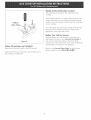
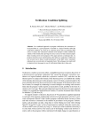
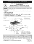
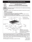
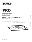
13" (33 cm) max. depth
.
for cabinet installed above
cooktop
t
30" (76.2 cm) Min.
Clearance Between the
Top of the Cooking
Platform and the Bottom
of an Unprotected Wood
or Metal Cabinet
cutout and nearest
between
rearsurface
edge of
combustible
"_
24" (61 cm)Min.
when Bottom of Wo_
or Metal Cabinet is -Protected by Not Less
Than I/8" Flame
Retardant Millboard
Covered With Not Less
Than No. 28 MGS
Sheet Steel, 0.015"
(0.4 mm) Stainless
Steel, 0.024" (0.6 mm)
Aluminum or 0.020"
(0.5 ram) Copper
"
18" (45.7 cm)
Min.
'P
It is not recommended to use
drawer underneath cooktop.
_To
eliminate tile risk of
burns or fire from reaching over heated
surfaces, cabinet storage space located
above tile cooktop should be avoided. If
cabinet storage is provided, risk can be
reduced by installing a range hood that
projects horizontally a minimum of 7"
(17.8 cm) beyond tile bottom of the
cabinets.
Figure 3 - CABINET DESIGN
30" (76.2 cm) min.
clearance between
the top of the
cooking platform and
the bottom of an
unprotected wood or
metal cabinet.
Wall
Outlet
Location
The conversion must be performed by a qualified service
technician in accordan(e with the kit instructions and all
_
local codes and requirements. Failure to follow
instructions could result in serious injury or property
damage. Tile qualified agency performing this work
assumes responsibility for the conversion.
4 ,,_
(I0.2 cm)
.....
Failure to make the appropriate
5"
0
Recommended
area for 120V
grounded
outlet on rear
wall.
(12.7 cm)
,
'm
|
|
i
16
(40.6 cm)
_
ii
_CENTRE
_LINE
OF UNIT
NOTE: If an
outlet is not
available, have
one installed by
a qualified
technician.
conversion can result in serious personal injury and
property damage.
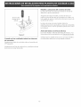
Important:
Remove all packing material and
literature from cooktop before connecting gas and
electrical supply to cooktop.
Install
Pressure
1
Do not make the connection too tight.
The regulator is die cast. Overtightening may crack the
regulator resulting in a gas leak and possible fire or
explosion.
I
,
"_
Figure 4
GCENTR
LLINE
E
OFUNIT
an Adequate
Gas Supply
This cooktop is designed to operate on natural gas at 4"
(10.2 cm) of manifold pressure only.
A pressure regulator is connected in series with the
manifold on the cooktop and must remain in series with
the supply line.
For proper operation,
the maximum inlet pressure to
the regulator must be no more than 14" (35.6 cm) of
water column (W.C.) pressure.
For checking the regulator, tile inlet pressure must be at
least 1 "(2.5 cm) (or 2.5 kPa) greater than the regulator
manifold pressure setting. The regulator is set for 4"
(10.2 cm) of manifold pressure, the inlet pressure must
be at least 5" (12.7 cm).
Tile gas supply line to the range should be 1/2" (1.3 cm)
or 3/4" (1.g cm) pipe.
LP/Propane
Gas Conversion
This appliance can be used with Natural gas or LP/
Propane gas. It is shipped from the factory for use with
natural gas.
A kit for converting to LP gas is supplied with your
cooktop. The kit is marked "FOR LP/PROPANEGAS
CONVERSION".
GAS FLOW
_
Manual
Shutoff
Valve
Provide
Regulator
Install the pressure regulator with the arrow on the
regulator pointing up toward the unit in a position where
you can reach the access cap.
,
/A"
FUare
Pressu_-e
Flare
Union
Union
......
Reg_Bator
.......
OntN
_-_
Off
F[exibme Connector
All connections must be wrench4ightened
Figure 5
Assemble the flexible connector from the gas supply pipe
to the pressure regulator in tile following order:
1. manual shutoff valve
2. 1/2" (1.3 cm) nipple
3. 1/2" (! .3 cm) flare union adapter
4. flexible connector
5. 1/2" (1.3 cm) flare union adapter
6. 1/2" (1.3 cm) nipple
7. pressure regulator
Use pipe-joint compound made for use with Natural and
LP/Propane gas to seal all gas connections. If flexible
connectors
are used, be certain connectors are not
kinked.
Thesupplylineshouldbeequippedwithanapproved
shutoffvalve.Thisvalveshouldbelocatedinthe same
roomasthecooktopandshouldbeina locationthat
allowseaseof openingandclosing.Donot blockaccess
to theshutoffvalve.Tilevalveisfor turningonor
shuttingoff gasto theappliance.
Grounding
Instructions
IMPORTANT Please read carefully.
For personal
grounded.
safety, this appliance
must be properly
The power cord of this appliance is equipped with a 3prong (grounding) plug which mates with a standard 3prong grounding wall receptacle (see Figure 7) to
minimize the possibility of electric shock hazard from the
appliance.
The wall receptacle and circuit should be checked by a
qualified electrician to make sure the receptacle is
properly grounded.
Shutoff
Valve
Preferred Method
Open position
Figure 6
Once the regulator is in place, open the shutoff valve in
the gas supply line. Wait a few minutes for gas to move
through tile gas line.
Grounding type
wall receptacle
Check for leaks. After connecting the cooktop to the
gas supply, check the system for leaks with a
manometer. If a manometer is not available, turn on the
gas supply and use a liquid leak detector (or soap and
water) at all joints and connections to check for leaks.
/
(
cord with 3-prong
grounding plug,
Do not use a flame to check for leaks
from gas connections. Checking for leaks with a flame
may result in a fire or explosion.
Tighten all connections
if necessary to prevent gas
leakage in the cooktop or supply line.
Check alignment of control knob valves after
connecting the cooktop to the gas supply to be sure the
cooktop manifold pipe has not moved. A misalignment
could cause the valve stems to rub on the control panel,
resulting in a gas leak at tile valve.
Disconnect this cooktop and its individual
shutoff
valve from the gas supply piping system during any
pressure testing of that system at test pressures greater
than 1/2 psig (3.5 kPa or 14" (35.6 cm) water column).
tsotate the cooktop from the gas supply piping
system by (:losing its individual manual shutoff valve
during any pressure testing of the gas supply piping
system at test pressures equal to or less than 1/2 psig
(3.5 kPa or 14" (35.6 cm) water column).
Electrical
Requirements
120 volt, 60 Hertz, properly grounded branch circuit
protected by a 15 amp circuit breaker or time delay fuse.
Do not use an extension cord with this cooktop.
f
Figure 7
Where a standard 2-prong wall receptacle is installed, it
is the personal responsibility and obligation of the
consumer to have it replaced by a properly grounded 3prong wall receptacle.
Do not, under any circumstances, cut or remove the
third (ground) prong from the power cord.
Disconnect electrical supply cord from
wall receptacle before servicing cooktop.
Cooktop
Installation
1. Visually inspect the cooktop for damage.
2. If you are installing the optional Stainless Steel
backsplash, first fix it at the back of the cooktop using
the screws supplied with the kit and follow the
instructions attached.
3. Set the cooktop into the countertop cutout.
NOTE: Do not use caulking compound; cooktop should
be removable for service when needed.
2.
Check Operation
Refer to tile Use and Care Guide packaged with the
cooktop for operating instructions and for care and
cleaning of your cooktop.
Do not touch
hot enough
the burners,
Check the Igniters
Operation of electric igniters should be checked after
cooktop and supply line connectors have been
carefully checked for leaks and the cooktop has
been connected to electric power.
To operate the surface burner:
A. Push in and turn a surface burner knob to the
They may be
to cause burns,
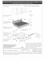
tnstaI] Burner Caps
This cooktop is equipped with sealed burners as
shown (see Figure 8).
A. Unpack your burner heads and burner caps.
B. Place burner head over each gas orifice,
matching the head with the orifice size. Be
careful not to damage the electrode while
placing the head over the orifice, Make sure
electrode fits correctly into slot in burner head.
C. Place a burner cap on each burner head,
matching the cap size to the head size. Each
burner cap has an inner locating ring which
centers the cap correctly on the burner head.
D. Be sure that all the burner caps and burner
heads are correctly placed BEFOREusing your
cooktop.
Turn on Electrical Power and Open Main Shutoff
Gas VaIve
B.
LITE position. You will hear a small ticking noise;
this is the sound of the electric ignitor which
lights the burner.
After the burner lights, turn to the desired flame
size. Tile controls do not have to be set at a
particular mark. Use the marks as a guide and
adjust tile flame as needed.
4_
Adjust the "LO" or "SIMMER" Setting of Surface
Burner VaJves (see Figure 9}
Push in and turn each control knob to the "LO" (or
"SIMMER") setting. The "LO" setting of each
burner has been set at the factory to the lowest
setting available to provide reliable reignition of the
burner. If it does not stay lit on the"LO" setting,
check the setting as follows.
_Be
careful when performing this
operation.
Burner C_
A.
B.
Allow cooktop to cool to room temperature.
Light all burners by turning each control knob to
LITE until burners ignite, and then set them at
"HI".
C. _turn
the knob to the LOWEST POSITION.
D. If burner goes out, readjust valve as follows;
Remove the surface burner control knob, insert a
thin-bladed screw driver into the hollow valve
S
stem and engage the slotted screw inside. Flame
size can be increased or decreased with the turn
of tile screw. To increase flame size turn the
screw counterclockwise and to decrease turn
Cooktop
clockwise. Adjust flame until you can quickly
turn knob from HI to LOWEST POSITION without
Burner Head
Gas Opening
E.
Figure 8
NOTE: There are no burner adjustments necessary on
this cooktop.
extinguishing the flame. Flame should be as
small as possible without going out.
If you need to adjust another burner, repeat tile
steps from A to D above until all burners operate
properly.
Model
and Serial Number
Location
The serial plate is located on the underside of the
cooktop.
When ordering parts for or making inquires about your
range, always be sure to include the model and serial
numbers and a lot number or letter from the serial plate
of your cooktop.
Hollow
Valve Stem_
Your serial plate also tells you the rating of the burners,
tile type of fuel and the pressure the cooktop was
adjusted for when it left tile factory.
Before
You Call for Service
Read the Before You Call for Service Checklist and
Figure 9
operating instructions in your Use and Care Guide. It
may save you time and expense. The list includes
common occurrences that are not the result of defective
workmanship or materials in this appliance.
When All Hookups
are Complete
Make sure all controls are left in tile OFF position.
Make sure the flow of combustion and ventilation air to
the cooktop is unobstructed.
Refer to your Use and Care Guide for Sears service
phone numbers, or call 1-800-4-MY-HOME ®.
Notes:
Notes:
10
LA INSTALAaON
Y EL SERVlaO DEBEN SER REAUZADOS
POR UN INSTALADOR CAUF?CADO.
IMPORTANTE: GUARDE ESTAS INSTRUCaONES
PARA USO DEL
INSPECTOR ELF:CTR_CO LOCAL
LEA Y GUARDE ESTAS INSTRUCaONES
PARA FUTURAS REFERENaAS
_F!_
Si todas [as instrucdones de _ste manua[ no son observadas a [a [etra, sepuede ocurrk incendios o
exp[osiones que pueden causar daffos materia[es, [esioneso [a muerte.
PARASUSEGUR[DAD:
-- No aJmaceneo uti[ice gaso[ina u otros vapores y [iqu[dos inflarnab[es cercade 6ste o cuaJquierotto artefacto.
-- QUEHACERS[HAY FUGASDEGASAE
No intente de encender ning_n artefacto
No toque ningun interruptor el@trko; no uti[ice ningun aparato tOl_fonko en su edifido.
L[ameinmediatamente el abastecedor de gasdesde el te[_fono de un vedno. Siga [as instrucdones de[ abastecedor de gas.
Encasoque no puede contactare[abastecedor de gas [[arnea[ departamento de bomberos.
-- La[nsta[ad6n y el serv[do t_[_fonico deben serreaJizadospot un insta[ador caHficado,pot un servic[otecn[co certffkado o
pot el abastecedor de gas.
* 30" (76,2 cm) rain para un armario
protegido
24" (61 cm) rain para una superficie no
Para [a Insta[adOn
Est_indar:
30"
(76.2 cm)
Min.*
Dimensiones de [a
parrilla de cocinar a
gas
C
<bertura
de 4"
X 4"
(102cm
x
102cm) parael suministro de gas
7¼" (18,4 cm)
Abertura de 2" (5,1 cm)
de diametro para hater
pasar el cable de
a[imentaci6n,
F
Dimensiones de[ hueco_
para [a parrilla de
cocinar a gas
No deslizar
Los torni![os
dentro
q
**Nota:
G
de[ hueco
que sobresaJen
inferior
de [a unidad pueden
acabado
inferior
de[ frente.
adecuada
de [a cocina
Por favol; aseg0rese de
respetar estas dimensiones,
"D" refleja una
dimension terminada que se recomienda para
de la alacena,
de la parte
daffar
"D & E" son criticos para [a instalacion
socavar
el
esta
dimension
FJgura 1
DrMiiSioN!S
DEi
HUiCO
MQDELQ A. ALTURA B.ANCHURA C PROEUNDIDAD
36 (91.4)13s_/_(9"l.'l)
I 2s<63s> 73A(19,7)
y ajustar
en
el
momento de la insta[acion de[ aparato debido
a [a variaciOn de los materia[es de [a cocina,
ALTURA
E*_
F
ANCHURA
G
3sw_(91.3)I 3s_/_(s9.4)
I 22(55.9)I'lV_(2.9)Max.
Todas las dimensiones se dan en pulgadas (cm).
La dimension F incluye un espacio de 5" por debajo de la plancha de
cocinar para la conexion de la I[nea de suministro de gas.
NOTA: Se adjunta los diagramas de cables de esta plancha de
cocinar con el tibreta.
H:PiOFUND DAD
PORDEBAJODELA
PLANCHA
DE
€OoNAR
I
7%(19,I)
318201459 (0407) Rev.A
English - pages 1-10
EspaPio[ - p_iginas 11-19
Diagrama de [a insta[adOn alcimbrica p_igina - 20
* 30" (76.2 cm) rain para un armario protegido.
24" (6! cm) rain para una superficie no protegida.
Para ver la Instalaci6n con el Panel Protector Opcional de
Acero Inoxidable.
30"(76.2 cm)
Min.*
Dimensiones de la parrilla
de cocinar a gas
Panel Protector Opcional
de Acero Inoxidable de -9" (22,9 cm)
C
***Nota
Se aplica s61o en
caso de Panel Protector.
Abertura de 4" X 4" para el
suministro de gas.
Abertura de 2" (5.1cm)
de diametro para
pasar el cable de
alimentaci6n.
71/4"(184 cm)
F
Dimensiones del hueco
para la parrilla de
cocinar a gas
1"(25
cm)
**Nota:
"D & E" son criticos para [a instalaci6n adecuada
de [a cocina
Por favor, aseg0rese de respetar estas
No desJizar dentro deJ hueco de Ja aJacena.
Los tomiJJos que sobresaJen de Japarte
inferior de la unidad pueden daffar el
acabado inferior de[ frente.
dimensiones,
se recomienda
Figura 2
,
"D"
refJeja una dimensi6n
momento
de la instalaci6n
del aparato
variaci6n de los materiaJes de [a cocina
DiMEN%NEiDEi
HUEco
_6(91,4)35Vs{91.I
25(63,5)
7X{19,7)
35_s/_6(91,3)
E**
353/_6{89.4)
Todas las dimensiones se dan en pulgadas (cm).
12
POP DE
LA
F
22(55.9)
que
y ajustar en el
debido
a [a
H, PROFUNDIDADJ. HUEOO
MODEEo
ALTURA
ANiHU%
CRRoFUNDALTU%
% D I
D**
terminada
para socavar esta dimensi6n
G
IV8(2.9) Max.
DELPANEL
PLANCHA
DE
COONAR
PROTECTOR
7V2(19.I)
Notas importantes
medidas de seguridad. Vienen con el Manual del Usuario.
Lea atentamente el manual.
para el insta[ador:
1. Lea todas las instrucciones de instalacion antes de
realizar la instalaci6n de la plancha de cocinar.
2. Retire todos los articulos de embalaje antes de realizar
las conexiones el6ctricas a la plancha de cocinar.
3. Observe todos los c6digos o reglamentos estatales
4. Aseg(_rese que el consumidor tenga estas instrucciones.
5. NOTA: Para la utilizaci6n a mas de 2 000 pies de altura,
la potencia del aparato debera set reducida de 4 por
ciento a cada 1 000 pies adicionales.
Notas importantes
• AsegQrese
que ta plancha de codnar
sea instaJada
y puesta a tierra correctamente
pot un instalador
o t_cnico
calificado.
• La plancha de cocinar
debe conectarse
eJ_ctricamente
a tierra de acuerdo
con los c6digos
locales o, de no existir,
con el c6digo
el_ctrico
ANSI/NFPA
No. 70 - eltima
edici6n en los Estados
Unidos, or in Canada, con el Canadian
EJectricaI
para el consumidor
Code, CSA C22.1 Parte 1.
• Los quemadores
pueden
encenderse
manualmente
durante
una interrupci6n
de[ suministro
ei_ctrico.
Para encender
un quemador,
mantenga
un f6sforo
encendido
en el extrerno
de[ quemador,
[uego
gire suavemente
[a per[Ha hasta LITE (encendido).
Tenga cuidado
a[ encender
los quemadores
en
forma
manual
Guarde todas las instrucciones con su manual del usuario
para futuras referiencias.
Juego de Relleno
para Ajuste
de
Profundidad
#903051-9010
Esta cocina ha sido diseflada para reemplazar la unidad
existente. Si la profundidad de la abertura de su cocina es
mayor que 7¼" (18,4 cm.) y menor que 8Y2" (21,6 cm.),
puede ordenar un juego de relleno gratuito Ilamando al
Centro de Partes y Reparacion Sears al 1-888-SUHOGARsM.
Accesorios
Opcionales
• No deje art_cu[os
que interesan
los ni_os en los
armarios
que est_n sobre [a [a plancha de cocinar.
Les podr[a causar quemaduras
graves si intentan
subirse para alcanzarlos.
• Para eliminar
el riesgo de extender
pot endma
de
los quemadores
superiores,
deber[a
evitar e[
espado
de aimacenamiento
de[ armar[o,
tocalizado
pot encima de estos quemadores
• Gradue el tama_o
de ia llama de modo que no
sobrepase
el borde de[ utensi[io
de codna.
Demasiada llama es peligrosa.
• No utilice jam_s ta cocina como ca[efactor.
El uso
prolongado
de la cocina sin la ventilacion
adecuada
puede ser peligroso.
• Mantenga
el _rea cerca de este artefacto
o de
cualquier
otto artefacto
despejada
de sustancias
combustibJes,
gaso[ina
y otros [[quidos
inflamabIes.
Se puede ocurrir incendios o
explosiones.
Disponibles:
Juego de Panel Protector Optional de Acero Inoxidable
de 9" (22,9 cm) #903048-9010
Se puede ordenar a traves del Centro de Partes y
Reparaci6n Sears, Ilamando al 1-888-SU-HOGARsM.
INSTRUCCIONES DE
SEGURIDAD IMPORTANTES
La instalaci6n de esta plancha de cocinar debe realizarse
en conformidad con los codigos locales o, si estos no
existen, con el National Fuel Gas Code ANSI Z223.1/
NFPA54 - (Htima edicion en los Estados Unidos, o en
Canada, con el Canadian Fuel Gas Code, CAN/CGA B149
y CAN/CGA B149.2.
EI suministro
ei_ctrko a ta piancha
de cocinar debe de set cerrado durante tas
conexiones a [a [[nea. De to contrario se puede
resu[tar [esiones graves o [a muerte.
La instalaci6n de aparatos disefiados para instalacion
en casas prefabricadas (m0viles) debe conformar con el
Maufactured Home Consturction and Safer Standard,
titulo 24CFR, parte 3280 [Anteriormente el Federal
Standard for Mobil Home Construction and Safety,
tltulo 24, HUD (parte 280)] o cuando tal estandar no se
aplica, el Standard fo Manufactured Home Installation,
ANS!/NCSBCS 225.1, o con los codigos locales.
El diseflo de esta plancha de cocinar cuenta con la
aprobaci6n del CSA international. AI igual que todos los
artefactos a gas que generan calor, deben seguirse ciertas
13
13" (33 cm) m_x,
30" (76.2 cm) rain. de
espacio entre la parte
superior del fogon y la
parte inferior de un
armario de madera o
metal sin proteccion.
24" (6! cm)rain.
cuando la parte inferior
del armario de
madera o metal esta
protegida por una placa
cortafuego retardante
de llama de no menos
de 1/4", cubierta con
una lamina de acero
msg no inferior al No.
28, de acero inoxidable
de 0.015", aluminio de
0.024" o cobre de
0.020".
1 "(2.5 cm) Mfnimo distancia
entre el borde posterior del
\
hueco y lamas cerca
_'_ superficie combustible por
encima del mostrador.
/
18" (45.7 cm)
M[n.
30" (76.2 cm) M[nimo de
espacio entre la parte superior
de la plataforma de la
plancha de co(inar y el fondo
de una madera non protegida
o armario metalico.
No es recomendable utilizar
cajones debajo de la estufa.
T!_
Para eliminar el riesgo
de alargar sobre los unidades en
calentamiento de la superficie, deber[a
evitarse el espacio de almacenamiento
del armario, ubicado sobre las unidades
delasuperficie.
Sisecuentaconeste
espacio, se puede disminuir el peligro
instalando una cubierta de cocina que se
extienda horizontalmente en 7" (I 7.8
cm) minimo por sobre la parte inferior
delantera en los armarios.
DE----------AMODEL
B,
PLANCHA DE
COCJNAR DE
36" (91.4 cm)
36" (91.4 cm)
Figura 3 - DESEF_ODEL ARMARtO
14
EsPaci0
C: Espacio--
rninimQ
desdeel minim0 desde
ladoizquierdoelladoderecho
I
7" (17.8 cm)
7" (17.8 cm) j
Ubicad6n
de [a toma de corriente
Si desea hater la conversi6n para utilizar el gas propano,
use las piezas (:on orificios fijados provitos en el paquete
del manual de instrucciones para la instalaci6n en el
paquete escrito "PARA LA CONVERSIONEN GAS
PROPANO".
de [a pared
(10.2
4" CrT_O
[
Para hater la conversi6n del gas natural al gas propano, es
necesario utilizar el servicio de un t6cnico calificado, in
acuerdo con las instrucciones del fabricante y todos los
c6digos y reglamentos reguladores. Si todas las
instrucciones no son observadas, se puede ocurrir severos
lesiones o danos materiales. La agencia calificada que
hate el trabajo asuma la responsabilidad para la
conversi6n.
(12.7 cm)
Area recomendada
la toma de corriente
a tierra de 120V en
la pared posterior,
NOTA: Si no existe
una toma de
corriente, contacte a
un electricista
calificado para
,
1
|
|
|
qDEL
16"
_APARATO (40.6 cm)
observada,
materiales.
1
[mportante:
Retire todos los articulos de embalaje y
folletos de la cocina antes de realizar las conexiones de gas
y el6ctricas a la cocina.
I
Instaiaci6n
de[ reguiador
de presi6n
Instale el regulador de presi6n (:on la fie(ha del regulador
apuntando hacia la unidad en una posici6n que permita
alcanzar la tapa de entrada.
instalaclon
.realizar...la
GL DEL
APARA [0
__
No ajuste demasiado la conexi6n. El
regular esta fundida a presi6n. AI ajustar demasiado se
puede romper el regulador causando una fuga de gas y
un posible incendio o explosi6n.
Figura 4
Provea
Si la conversi6n apropiada
no esta
se puede ocurrir severos lesiones o daFlos
un adecuado
suministro
de gas
Esta plan(ha de cocinar esta diseFlada para utilizar gas
FLUJO DEL GAS
natural de 4" (10.2 cm) de presi6n mOltiple solamente.
VaUvuUa de
cierre
rnanua[
_
Regumador
Uni6n
Uni6n
de p_esidn
Se conecta un regulador de presi6n en serie al mOltiple de
la plan(ha de codnar y debe permanecer en serie con la
I[nea de suministro de gas.
Cone(tot
Para que manejo correcto, la presi6n de entrada
maxima hacia el regulador no debe exceder 14" (35.6 cm)
de presi6n de la columna de agua.
(off)
Todas las conexiones deben ajustarse con
una Ilave de tuerca
Figura 5
Para controlar el regulador, la presi6n de entrada debe ser
de al menos 1 " (25 cm) (o 2.5 Kpa) mayor que el ajuste
delapresi6ndelmOltipledelregulador.
EIreguladorse
ajusta a 4" (!0.2 cm) de la presi6n del mOltiple, la presi6n
de entrada debe de set de al menos 5" (!2.7 cm).
Monte el cone(tot flexible del tubo del suministro de gas
al regulador de presi6n en funcionamiento:
1. vdvula de cierre manual
2. boquilla de 1/2" (! .3 cm)
3. adaptor de 1/2" (1.3 cm)
4. cone(tot flexible
5. adaptator de I/2" (1.3 cm)
6. boquilla de I/2" (I .3 cm)
7. regulador de presi6n
La I[nea de suministro de gas pot el homo deberfa tenet un
tubo de 1/2" (! .3 cm) o de 3/4" (1.9 cm).
Conversi6n
fJexibUe
Apagado
de gas propano/licuado
Esta plan(ha de cocinar ha sido diseFlada para utilizar gas
naturalogaspropano.
Hasidofijadaenlafabricapara
utilizarse con gas natural.
15
Utilice un compuesto de tubo articulado para uso de gas
natural y propano para sellar todas las conexiones de gas.
Si se utilizan conectores flexibles, aseg0rese que los
conectores no estan torcidos.
Eltubodesuministro
degasdebreria
incluirunavalvulade
cierrecertificada.
Estavalvuladeberiaestarubicada
enla
mismahabitaci6n
delaplancha
decocinary deberia
estar
enunlugarquepermitaunaaberturay cierrefaciles.No
bloqueelasentradasdelavalvuladecierre.Lavalvula
sirveparaabriro cerrarel pasodelgasalartefacto.
Requerimientos
el_ctricos:
Un circuito derivado conectado correctamente a tierra de
120 voltios, 60 Herz protegido por un interruptor
autom_itico de 15 amp o un fusible de retardo. No utiHce
un cabJe fJexible de extensi6n en esta plancha de
cocinar.
[nstrucdones
tMPORTANTE
para [a puesta
Por favor,
a tierra
lea atentamente,
Como medida de seguridad
personal
debe conectarse
a tierra correctamente.
est_ artefacto
El cable de encendido de este artefacto incluye un
enchufe de tres patas (a tierra) que calza con un enchufe
de pared de tres patas de conexion a tierra (ver Figura 7)
para disminuir la posibilidad de peligro de choques
electricos desde el artefacto.
de cierre
METODO
PREFERIDO
Figura 6
encendido.
Abra la valvula de cierre en el tubo de suministro de gas.
Espere unos minutos para que el gas pase a trav6s del
tubo de gas.
Enchure de
pared a tierra
Cablo de encendido
con enchufe de tres
patas a tierra
Vedffque si hay fugas. Para verificar si hay fugas en
eJ eJectrodom_stico se debe de seguir Jas
instrucdones del fabricante. Luego de conectar la
cocina al gas, verifique el sistema con un manometro. Si
no cuenta (:on 6ste instrumento, de la vuelta al suministro
de gas de la cocina y utilice un detector de fugas I[quidas
(o agua y jab6n) en todas las articulaciones y conexiones
para verificar si existen fugas.
Un electricista calificado debe verificar el enchufe de pared
y el circuito para asegurar que el enchufe esta conectado a
tierra correctamente.
No use ningOn tipo de llama para
verificar si hay fugas de gas. Verifique si hay fugas con
una llama puede occasionar incendio o explosion.
En caso de encontrarse con un enchufe de pared de dos
patas, es la personal responsibilidad y la obligaci6n del
consumidor reemplazarlo por el enchufe de pared a tierra
de tres patas correspondiente.
Figura 7
No debe, bajo ninguna circunstancia cortar o retirar ta
tercera pata (tierra) det came de encendido
Aiuste todas Jas conexiones en caso que sea necesario,
para evitar fugas de gas en la cocina o en el tubo de
sumininistro de gas.
Desconecte el cable del suministro
el(_ctrico del enchufe de pared antes de reparar la
plancha de cocinar.
Veriffque Ja alineaci6n de Jas v_lvuJas luego de
conectar la plancha de cocinar al suministro de gas para
asegurar que no se ha movido la valvula del mOltiple de la
plancha de cocinar.
Instalacion
de la Tapa de Cocina
1. Inspeccione visualmente la tapa de la cocina para ver
siesta danada.
2. Siva a instalar el Panel Protector Optional de Acero
Inoxidable, primero coloquelo en la parte posterior de
la tapa de la cocina usando los tornillos provistos con
el juego y siga las instrucciones provistas.
3. Coloque la tapa de la cocina en la marca de la
mesada.
Desconecte la cocina y su v_Jvula de derre individual
del sistema de tuber[a del suministro de gas durante
cualquier ensayo de presion del sistema en ensayos de
presion superiores a 1/2 psig (3.5 kPa o 14" colomna de
agua).
Aparte Jacocina del sistema de tuber_a del suministro
de gas cierrando su valvula de cierre individual manual,
durante cualquier ensayo de presi6n del systema de
suministro de gas en ensayos iguales o inferiores a 1/2 psig
NOTA: No use un compuesto de calafateo; la tapa de la
cocina se debe poder desmontar para revisarla.
(3.5 kPa o 14" colomna de agua).
16
VerifiqueJaoperaci6n
2. Abierte eJ suministro eJ_ctrico y ta v&lvuJa de
derre principal
del gas.
Refiera
al Manualdel Usuarioquevieneconlaplancha
decocinarparalasinstrucciones
defuncionamiento
yel
mantenimiento
y lalimpieza
desuplancha
decocinar.
3. Verifique los dispositivos de encendido
La manipulation de los dispositivos de encendido
Notoquea losquemadores.
Pueden
estarsuficientemente
el6ctrico deber[a verificarse tras haber revisado
calientes
parcausar
quemaduras.
detenidamente la plancha de cocinar y los conectores
del tubo del suministro de fugas y tras haber conectado
1. tnstalad6nde lastapasdequemadores
la plancha de cocinar al suministro electrico.
Estaplancha
decocinarestaequipada
conquemadores
Para operar en Jasuperficie det quemador:
sellados
comosemuestra
(Figura
8)
A. Presione y gire la perilla de control hasta LITE.Se
A. Retirelashornillasy loscasquetes
delacaja.
escuchara a un pequeFlo ruido. Este es el ruido
B. Ubiqueunacabeza
dequemador
sobrecada
producido por el dispositivo de encendido el_ctrico
orificiodegas,y alineelacabezaconeltamanodel
cuando enciende el quemador.
orificio.Asegeresedenoda_ara[e[ectrodo
B. Una vez que el quemador esta en(endido, gire
cuandoestaubicandoJacabezasobreel
hasta obtener el tama¢lo de la llama deseada. No
odfido. AsegOrese
deubicarelelectrodo
es necesario ajustar los controles en una marca
correctamente
adentrodela ranuraenlacabeza
del
determinada. Use las marcas como gu[a y ajuste la
quemador.
llama segOn se desea.
C. Ubiqueuncabezal
dequemador
sobrecadacabeza
dequemador,
y alineeeltamanodelcabezal
al
4. Verifique
eJ ajuste "LO" O "SIMMER"
de tas
tamaFlo
delacabeza.
Cada cabezal tiene un anillo
vSJvuJas de superficie de quemador (vet Figura 9)
interiormente elevado en las partes inferiores del
lado para ayudarle a ubicar correctamente el
cabezal sobre la cabeza.
D. AsegOrese de colocar todas las hornillas con sus
respectivos casquetes ANTES de utilizar la pancha
de cocinar.
Presione y gire el botOn de control al ajuste "LO" (o
"SIMMER").EI ajuste "LO" de cada quemador ha sido
creado en la fabrica para fijarse al menor ajuste
disponible para entregar un reencendido confiable del
quemador. Si no queda encendido en el ajuste "LO',
verifique el ajuste "LO" como se muestra a
continuation.
Tapa del
quemador
Tenga cuidado al proceder con esta
operaci6n.
A. Deje que la cocina se enfrle a temperatura
ambiente.
B. Enciende todos los quemadores girando cada botOn
de control hasta LITEpara encender los quemadores
y fijarlos en "HI".
C. Gire rapidamente el quemador hasta LOWEST
POSITION.
D. Sielquemadorseapaga,
reajustelavalvula
como
se muestra a continuaciOn:
Retire el botOn de control del quemador, inserte un
destornillador de cuchillo delgado en el vastago del
agujero de la valvula y encaje el tornillo ranurado. El
tamano de la llama se puede aumentar o disminuir
girando el tornillo. Para incrementar la talla de la
llama, de vuelta el tornillo en el sentido de las
agujas del reloj y para disminuir la talla, de vuelta
en la direcci6n opuesta.Gradue la llama hasta que
se pueda girar r@idamente hacia abaio desde HI
hasta LOWEST POSITION sin apagar la llama. La
llama deberia set Io mas baia posible y estable sin
apagarse.
E. Si se desea aiustar otto quemador, repita los pasos
de A a D descritos hasta que los quemadores
funcionen correctamente.
Superficie de la
plancha de cocinal
Base del
quemador
Abertura
del gas
Figura
8
NOTA: No es necesario realizar ajustes en los quemadores
de esta plancha de cocinar.
17
Mode[o
y ubicad6n
del nOmero
de serie
La placa de n0mero de serie est4 ubicada en el lado de
abajo de la caja de quemadores.
Aseg0rese de incluir el modelo, n0mero de serie y el
n0mero o letra del Iote que se encuentran en la plata, en
todo pedido de partes o solicitud de informaci6n acerca de
su plancha de cocinar.
Elhuecodel
vastago
dela
vdvula
La placa de n0mero de serie tambi6n indica las
especificaciones de los quemadores, el tipo de combustible
y la presi6n para la cual fu@ajustada la plancha de cocinar
en la fabrica.
Antes de llamar al servido
Figura
Cuando se hart realizado
de conexi6n
9
todos
t@cnico
Lea la lista titulada "Evitando Llamadas de Servicio" y las
instrucciones de funcionamiento en su Manual del Usuario
Verifique que los fusibles de la casa no se hayan fundido o
el cortacircuitos del homo no haya saltado o abierto.
los sistemas
Aseg0rese que todos los controlos estan en la posici6n de
OFF (apagado).
Aseg0rese que el flujo de combusti 6n y ventilaci6n de aire
de la cocina no estan obstruidos
18
Notas:
19
TOP BURNER
IGNITER
OPTIONAL
DDEMABDR DE ENC_ND[BO
SLIpERIOR
DPBIONAi
BDUGJE D'ALLUr_AGE
BRULEUD
IONB_J
INTENCTRABEF4D
DERECIqO
INTER &llbM
RIGHT REAR
]
_z I
BK
TOnBURNER
IGmrER
OPIIBNAL
QUEHADOR DE Ef\CE\3]DO
SU_RIQ<
OPDIONAL
DDUG I E D" ALL UMAOE BRULEUR
i_
R_ Ii i
B
CAU r I ON :
I_
_LL
/dtREB
PROR
TD DISCONNECTION
_/HEN SERVICING
CONTRD! 5
_'[RING
ERROR CAN DR,USE iI'_P4OPER AND D_NG_ROLJS OPERATION
L]
B AR
VER I FY PROPER
\\\_
IONB_
INI ENC
DE
FRENTE
DEREO_
INTER ALLUN
RIGHT
FRON]
D _\
BKI
ETIOUETE
REAL IZAR
_LAHBRAJE
AFTER
5ERV I C I NG
TODOS LOS ALANDRES
ANTES DE DBBCONECTAR
PAR
ET MANTENi:VlENTO
DE LOS CONTROLEB
ERRC_ DE
PUEBE CAUSAR
UN FUNCiONAMIENTO
]NCORRECTO
Y PEL ]GROSD VERIOUE
S
El _UNCiON_HIENTO
CORREDiO
DESF_JES ©EL MANTEN!M]ENiO
EDTA
B_I
I
ETIOUETER
CHABUE
FL
AVANT
DRANCqEMENT
F_LJT CA F,ER tJk
FDNCT]ONNEP'ENT
BE L'APP_REIL
TOP _.;RNER
IGNITER
QLEPJs OR DE ENCN
I DE) ! LJPER[OR
DDLiQ I E D" ALLUVA_E
DRULEUR
LE
BEORANCHEHENT
DE CEbX
C]
OPER,GTION
D_NGER L
\,'[R
APR _ TOUT
REPARATION
UNE
[ER
ERREUR
I I
RE
BDN
[NT ENC
DE
CENTRD TRABERO
DER_CHO
[N]ER
ALLUM
CENTRE
ARRiEBE
B£ I
TOP LUKNER
ION[lEA
OUEP'AO_
BE ENCEf DI DO SUPE_I
BOUQIE
D' ALLUMAGE
DRULEUR
OPERAT [ ON
Of
Po
o
TOP BURNER
IGNITER
QUEHAD_
DE ENCENDIDO
SUPERIOR
BOUGIE
D'ALLUMADEDRULEUR
_
j BK I
1ONBd
INT ENC
DE
CENTRO iZOU]B_
I N_ER
ENTER _LLUM
FRONT
CENTRE
AV_NT
Jd
[GN SW
[NiENC/RASERO
[ZOUiERDO
lEFT
REAR
LEfT
F_JN[
ION S_
[N_ENC
DE
FRENTE [ZOUIERDO
[NER
ALUM
G AV
lOP BURNER
IGNilER
OUEHABOR DE ENCEND)DO
DOUBLE
IBNITER
MODDLE BOARD
CtJADRO DE HODUI 0 DE ENEEqD]BO
_( OC CONNECT ION AL / DHELIR
_Fr_
FRONT
IGN D_,
iN_ENE
BE
_REN_E
IZQO!ERDD
]N_ER
A_LUH
LEVI
REAR
/GNBW
]N_ ENg TR_b_'5
JZQUiERDC
INTER
A[LL_
OAR
D'ALLU_£GE
CENTER RON
ION S_
INTFNC
DE
CbNTRO {ZOUIERDO
IN _R¸_LUH¸
CENTRE AVfL_
CENTER REDR
ION S_
IN1 ¸ END
DE
C_NTRO TRAMP2
DERECHO
INTERAL!UH
BEN/RE
£RRIER_
Rl@i_
_RON
ION 5W
[N_ END
BE
FRENiE
B_i_CHO
[NTERA_LUM
D AV
RIGH
REAR
ION B_
IN/ENC
/RASERO
DERECHD
INTERALIbV
D £R
SUPERIOR
DRULEUR-_
_
TBF [JURNIR
IGNI FER
OD HADOR [),_ ENCEND]DO
StPER IOR
DOUBLE D" A! I LiHABE DRUI EUR
_
TAP BJRNER
[.%1 [ER
_E_ADOR
DE ENCE_,L]]DO
DDUG I _ D" AI I URROE
SUPERIOR
DRUL BUR
TOP BURNER
IGNITER
OUEHADOR DE ENCENDIDO
DUPER[OR
80UG[E
D'ALt
UHAGE DRUi BUR C3
]Df
BUF/NER [(NI TEA
O_E IADOR DE ENDE\D]DD
DUPERI OR
DDD_IE
D'ALLLJNAOE
DRULEUR
TOP BURNER
IGNITER
OUEMADDR DE ENCENDIDD
BOUG[E
SUPERIOR
D'ALLUMAGEDRU_EUR
3/ii('4
_i
0 _/:::_.,A
r) /
,