1
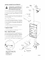
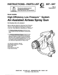
GAS BUILT-IN
models 8460
B675
INSTALLATION
CARE & USE
RECIPES
I
4356239 (343748)
CONTENTS
USE AND CARE
Important Instructions for Your Safety ,,, .......... .... ... .... .... ... ... .... ... ......... .............. .7-9
... ... 10
Your Oven and Its Features .................... ., ..........................................................
Using the Lower Oven ... .... .... .... .... .... .... ............................. ................... ..... ... 10
....... ... .....................................
................... 10
,, .,
Oven Vent ................. ,,, ........
10
......... ................ ,,., .................
Oven Ignition .............. ..............................................
1 1,12
Your Electronic Range Control ................................................................................
,, ..... 13
,, .. ,, ,., ........ .. ,,, .......... ..............
..........
,, ..
Oven Cooking
Broiling ......... ................................ ...... .... ... .... .... .... .......... ... .... .... ......................... 14
Continuous Cleaning Oven .... ... ... ... ........ ... .... ........... ... ........ ............................ 15
16
Cleaning Tips ., ....................................................................................................................
.............. ........ 17
Removable Parts ..... ......... ......... ,,.., .............................................................
SERVICE
Replacing the Oven Light .., ,..,,, ,....,,..., ,,,. ,,,....,... ,,...
.., ,... ,,,.., ,, ..,,, ,,.,,,,.,.,
18
,......,.
,,..,,....
,..,..
19
What to Do before Calling for Service
,...,,,....,,.. .,,.,,, ...,...., ,,..,,,...,,........, 20
Adjusting Oven Temperature ..,., .,,,
WARRANTY
GC0028
f
A
A
FOR YOUR SAFETY
If you smell gas:
I. Open windows.
2. Don’t touch electrical switches.
3. Extinguish any open flame.
4. Immediately call your gas supplier
FOR YOUR SAFETY
Do not store or use gasoline or other
flammable vapors and liquids in the
vicinity of this or any other appliance.
-_-../
A
L.P. Burner
Adjustments
1 he adjustments In the Installatlon Section must be made
bt?lOre you try10 use yourrange.
If you are using Liquified Petroleum Gas (bottled gas) all
I P adjustments in the Installatlon Section must be made
before use.
If your oven is not properly adjusted, flames may be too high,
or the oven may use too much
luel, releasetoxicfurnesorcook
poorly.
To insure safety for
yourself
and your
home, please read
your Owner’s Manual
carefully.
Keep it
handy for quick, easy
reference.
Pay close attention to
the safety sections of
your manual. You can
recognize the safety
sections by looking for
the A symbol or the
word safety.
2
/
.
A
.
WARNING: Improper
installation,
alteration, service or malntenance can cause lnjury or property damage. Refer to thls manual. For assistance or
addltlonal lnformatlon
consult a quallfled
Installer,
service
agency, manufacturer
(dealer) or the gas
suppller.
/
GNOT16
INSTA
INSTALLER:
Leave these instructions
the appliance.
with
ATION
OWNER:
use.
Keep these instructions
for future
Place the bottom of the template on a level base line,1 6-112’
above the floor. This will position the open upper oven door
about 37” above the floor.
TOOL LIST
1 l/8” drill bit
2. Electric or hand drill
3. Flat bladed screwdriver
4. No. 1 or No. 2 Phillips screwdriver
5. Pencil
6. Ruler and straight edge
7. Hand saw or saber saw
8. Pipe wrench
9. 518” wrench and l/2" wrench or adjustable wrench
LOCATION
Cabinet space, with 5 solid sides must be provided to
completely enclose the recessed part of your built-in oven
except for the vent thimble on outside vented units. See
Figure 1 for all necessary dimensions. A cutout 22” wide by
50-l/4” high must be made in the cabinet front. It is best to
make a template to insure accurate cutting.
It is important that the oven be installed at or above the
minimum height specified. The unit has been tested and
approved in accordance with safety standards at this height.
The oven vent area may get hot when the oven is in use.
Following these installation instructions will move the vent
area out of a range where it would likely be touched by small
children.
The cabinet must have a solid bottom. This solid bottom may
either be at the floor or 16-l/2” above the floor, level with the
bottom edge of the cutout opening. If the solid bottom is to
be at the floor, two runners, centered within the cabinet and
11” apart may be used to support the oven. Be sure the oven
support is solid enough to hold the weight of the unit - about
200 pounds. Also, be sure the support is level and straight.
There is no way to level the oven after installation.
Drafts inside the oven cabinet may affect safe use of your
oven. Any openings around gas and electric service outlets
may be sealed at the time of installation to prevent drafts.
OVEN AND CUTOUT
DIMENSIONS
24'
A
24'
Fig. 1
lNT026(342461)-1
GINS691
ELECTRICAL
GAS CONNECTIONS
CONNECTIONS
C;tlt?ck wrth your local L,tillties for eiectrical codes that apply
in your area. If there are no local codes, the National
Eilecirical Code, ANSI/NFPA No 70-I 990 must be followed.
You can get a copy by tiriting:
Do not operate the burners of this oven
when using L.P. (bottled) gas before
converting
the pressure regulator and
burner orifices for L.P. gas usage.
National Fire Protection Association
Ba?terymarch Park
Qumy, MA 02269
A:I &equate electrical supply and outlet must be used to
opt rate the electrical parts of your oven. The oven cord has
a ttiree prong plug and must be used with a properly
gro Jnded three hole outlet with standard 120 volt, 60 Hertz
AC household current
I
You must follow local codes when installing your built-in
oven. Check with your local utilities for codes and ordlnances that apply in your area. If there are no local codes,
you must follow the National Fuel Gas Code ANSl/Z223.11988. You can get a copy by writing:
American Gas Association
1515 Wilson Boulevard
Arlington (Rosslyn), VA 22209
install the electncar outlet below the oven on the right side.
It sl~ould be easily reached through cabinet doors below the
oven see Figure 5. A llole must be made In the cabinet for
the electrlcal hook-up
The gas supply must be shut off before removing an old over;
and stay off until the hookup of the new oven is finished. You
should know where your main gas shut off valve is located
iht preterred method c;f electrlcal hook-up is shown in Fig.
2 I! you do not have a grounded (three hole) outlet, have a
qualiilea electricjan change your old outlet or install a new
0 ne
Never reuse an old connector
oven.
A qroundlng adapter plug may be used to convert a two hole
o~tl?l to a three hole outlet until a grounded outlet can be
tnst,lllea. See Figure 3. rh1.sshould be done only temporar11yand only ofthe two hole outlet is properly polarized and
grounded. Have a qualified electrician test the outlet to be
surf’ ! meets all requirements.
Use 1/2”gas inlet pipe. The hole forthe gas inlet pipe should
be 9-114” to the left of the center line of the cabinet (see
Figure 4) and 23” behind the front surface of the cabinet
Connect a 112” coupling to the inlet pipe The top of the
coupling should be about 2-112” above the bottom edge of
the cutout opening (see Figure 4) Before you put Ihe oven
into the cabinet opening, connect the 1’2” reducer shut-off
valve to the coupling (see point A in Figure 4). This valve IS
supplied with the oven and is wire-tied to back of unit. The
manual shut-off valve must be Installed external to the
appliance in the gas line.
supply.
Do not under any circumstances
cut or
removegroundingprongfromovencord.
Failure to provide proper polarization
may create a hazardous condition.
POLARIZED
PROPERLY
Put the oven into the cabinet. NOTE The oven/broiler door
may be removed before inserting the oven rnto the cabinet to
lessen the weight. See the instructions In the Removable
Parts section of the Owners Manual for removing the door
RECEPTACLE
GROUNDED
METAL
a new
Be sure no strain is put on the connecting line assembly To
prevent gas leaks, put a pipe joint compound that resists the
action of L.P. gas, on the male (outside) threads only
Always unplug the oven cord before making any electrical repairs to the oven. When unplugging
the oven,
always grasp the plug, never the cord. Never use an
extension cord to connect the oven to the electrical
PRONG
PLIJG WITH GROUND
PROPERLY
POLARIZED
AND
G’3OIJNDED
RECEPTACI
E
when installing
When the oven is in place, remove the hookup and adjustment access covers at the lower oven back (Figure 5)
Reach through the access opening and connect the oven
tubing to the reducer shut off valve (see point B in Figure 5)
Use a 518” wrench to turn the fitting Tighten the fitting snugly
EYELET
RECEPTACLE
Fig. 2
PREFERRED METHOD
Fig. 3
TEMPORARY METHOD
4
GINS1 02
but do not force it Forcing could damage the fitting and
tubing and cause leaking
MAKING L.P. GAS ADJUSTMENTS
Apply lrquld leakdetector to all connectlons 111
the supply Ilne.
manifold ,Ind oven to test for gas leaks Do not use an open
flame 10 look for leaks Bubbles will form where any gas IS
leaking rum off the matn gas supply before you try to stop
a !eak After all leaks are stopped, turn on the gas supply and
recheck all connections for leaks before llghtlng burners All
leaks must be stopped before lighting any burners.
klt;jr e~t~ctrical and gas connections have been made, use a
1 E ‘drill t’lt !o droll holes In the cab/net front, through the holes
lr: it-10 3:‘z:i IrIm Secure lh+d oven In the cabinet with ihe
?‘r!PLYc>
rjro’Nfed
I .
A
If you are using L.P. (bottled) gas, all the
adjustments
described below must be
made before you make any burner adjustments or use the oven.
To adjust your oven for use with L.P gas, follow the steps
below.
Step 1: Adjust Pressure Regulator
NOTE: The pressure regulator is set for natural gas. To
use L.P. gas, the regulator must be adjusted.
1ocate the pressure regulator (see Fig. 5). Unscrew the cap
and remove the spring retainer, Fig 6 Turn the retainer over
and put it back into the cap so L P. is showing on the bottom
2nd of Ihe retainer Replace the cap
CAP
rc
SPRING
RETAINER
PRESSUREREGULATOR
Fig. 6
Slep 2: Adjust Burner Orifices
CAUTION:
The following
adjustment
must be made
before turning on the burner.
Failure to do so could
result in serious injury due lo high flames and toxic
fumes.
‘-!+.I r OFF VA\-‘JE t IEHC IF
REZiJIF(ED BY LG( AL REGULATIOIIS
lJse a 1 2” open entl or adjustable wrench to turn all orifice
hoods in the L P dIrectIon, about l-l:2 turns or until snug
See nerl page Do not overtighten or you may distort the
orifice hood and needle.
Pressure
Test Information
The max~rnuni allowable pressure for the regulator IS 14”
W C rhe minmurr pressure needed to check the regulator
setting 15 7” W C for natural gas or 11” W C lor L P gas
FqEGULATOR
CAUTION: The range and its individual shut off valve
must be disconnected
from the gas supply piping system during any pressure testing of the gas supply
system at test pressures in excess of 112 psig (pounds
per square inch gauge).
The range must be isolated from the gas supply piping
system by closing its individual shut off valve during
any pressure testing of the gas supply system at test
pressures equal to or less than 112 psig.
GINS54
5
MAKING BURNER ADJUSTMENTS
If you are using L.P. (bottled) gas, all the
adjustments described on the previous
page must be made before you make any
burner adjustments or use the oven.
AII oLt;ns are factory adjusted for use with the natural gas
used in most areas But since the gas In some areas may
be dillerent
you should check all adjustments
described
below If you areusing
be made.
L.P. gas, all the adjustments
K.lemove the oven boltoms as shown in the Removable
section of the owner s manual
Remove the shlpplng
f,orn the oven burners
Step 1: Adjust
-.
must
Parts
wires
1 ’ /-’
i,,
,
L P.
INNER CONE
OF FLAME
BROIL
“..-lT,BURNER
(i
Air Shutter
2
.a+
i urn I~ie burner lull or’ and check the flames Burner flames
rhould nol llulteror blow away from the burner They should
Foreign particles In
: t‘ bltie 111color with no trace of yellow
!~t? gas IIne may caL’;e an orange flame al first but this ~111
loor disappear
/’
/
i III~ flames are yellow or llutler.operi
the air shutter more
I !hey blow away from the burner close the air shutter more
t3!!:r;,:r flames ~houlri be checked
To adjust
frequently
air shutter:
! !:;t’ ,+screirrdrlver to lOosen the air shuller screw
<III snuller and retlgh:en the air shutter screw
Step 2: Adjust
Orifice
Adjust the
Hood
c:heck the Inner conu of the flame
It should be about 1 2’
lzng for the oven broiler burner (see below)
If the length ol
the inner cone of Ihe flame IS not correct, use a 1 2“open end
\vrench or adjustable ]olnt pliers lo adjust the onfice hood
o sllorlen Iht? coneL, tIghten the orlflce hood by turning In
1~~2I P directIon
To lengthen the cones loosen the orifice
Ii?od by turning In the Nat dlrectlon (see illustrations this
AIR SHUTTER
N---
A ACCESS OPENING COVER
B ELECTRICAL CONNECTION
d--
NAT
AIR SHUVER
SCREW
C TRIM CLIP
D ORIFICE COVER
E OVEN IGNITOR
6
GINS552
THANK YOU
for buying this product. We hope you enjoy many years of
safe, trouble-free service.
Please take a few minutes to read th/s sheet and the enclosed Use and Care Guide. Both contain
information that can improve your cooking results; they can also make it easier to maintain this
product. Most important. you’ll learn how to use this product safe/y. Save the Use and Care
Guide for future reference.
When reading the Use and
Care Guide . . I
Pq special attention to sections marked by
the following words.
These help you avoid accidents that could lead to injury or
death for someone using the product incorrectly.
These help you avoid damage to the product and/or other
prve fly
Keep your kitchen safe
Thousands of people are hurt every year in kitchen fires.
Read the warning precautions in your Use and Care
Guide. Make sure other household members know about
them, too.
Cooking fires can be dangerous because they usually
involve grease. Don’t use water on a grease fire; water
only spreads the fire. Also, never pick up a flaming pan.
Smother a flaming pan on the cooktop be covering it with
a well-fitted lid, cookie sheet or flat tray. Flaming grease
outside the pan can be extinguished with baking soda, or
if available, a multipurpose dry chemical or foam-type
extinguisher.
If a fire starts in the oven, keep the oven door closed and
turn off all control knobs. If product damage occurs, do not
use the oven. Contact a qualified technician for service.
“NOTE:” or “IMPORTANT:”
These sections give you helpful tips on using the product.
GSAF12
Important Safety Instructions
Gas cooking products have been thoroughly tested for safe and efficient operation.
However, as
with any appliance, there are specific installation
and safety precautions
which must be followed to
ensure safe and satisfactory operation.
To reduce the risk of fire, electrical shock, injury to persons, or damage when using the cooking
product, follow basic precautions, including the following:
FOR YOUR SAFETY
Do not store or use gasoline or
other flammable vapors and
liquids in the vicinity of this or any
other appliance. The fumes can
create a fire hazard or explosion.
If you smell gas:
1.
Open windows.
2. Don’t touch electrical
3.
Extinguish
4. Immediately
switches.
any open flames.
call your gas supplier.
1.
Read all instructions before using the product.
2.
Install or locate the product only in accordance
with the provided Installation Instructions.
3.
Gas fuels and combustion can result in potential
exposure to chemicals known to cause cancer or
reproductive harm. For example, benzene is a
chemical which is a part of the gas supplied to the
cooking product. It is consumed in the flame
during combustion. However, exposure to a small
amount of benzene is possible if a gas leak
occurs. Formaldehyde and soot are by-products
of incomplete combustion.
Properly adjusted
burners with a bluish rather than a yellow flame
will minimize incomplete combustion.
To the Installer:
Please leave thls Instruction sheet wlth the
product.
To the consumer:
Please read and keep this sheet for future
reference.
See your Use and Care gulde for addltlonal safety Information. Call your dealer or our
toll-free lnformatlon line if you have questions. We’ll be very glad to help,
INT112(344129)
GSAFl3
IMPORTANT SAFETY INSTRUCTIONS
Keep this book for later use.
Be sure your oven is installed and grounded properly by a qualified technician.
Always keep the oven area clear and free from
things that will burn, gasoline and other flammable
vapors and liquids.
Always change oven rack positions while oven is
cool.
After broiling, always take the broiler pan out of the
oven andclean it. Leftovergrease in the broiler pan
can catch on fire next time you use the pan.
Always use dry pot holders when removing pans
from the oven. Moist or damp potholders can
cause steam burns.
Always use care when opening oven door. Let hot
air and steam out before moving food.
Always follow cleaning instructions in this book.
Teach children not to play with oven controls or any
other part of the oven.
Be sure the oven is securely installed to a cabinet
that is firmly attatched to the house structure.
Weight on the oven door could potentially cause
the oven to tip and result in injury. Never allow
anyone to climb, sit, stand, or hang on the oven
door.
Never use water on a grease fire-it
spread the flames.
OVEN FIRE
Do not try to move the pan.
will only
Never try to repair or replace any part of the oven
unless instructions are given in this book. All other
work should be done by a skilled technician.
Never heat unopened food containers. Pressure
build up may make container burst and cause
injury.
Never leave jars or cans of fat or drippings near
the oven. Never let grease build up on your oven.
You can keep grease fires from starting if you
clean up grease and spills after each oven use.
Never use aluminum foil to line oven bottoms.
Improper use of foil could start a fire and cause
incomplete combustion.
Never block the flow of combustion and ventilation air through oven vents.
Never try to move a pan of hot fat, especially a
deep fat fryer. Wait until the fat has cooled.
Never leave children alone or unattended where
a oven is in use.
Never use your oven for warming or heating a
room. Such use can be dangerous and could
damage oven parts.
Never wear loose fitting or hanging clothes when
using your oven. Such clothes could catch fire
and cause serious injury.
Never use a towel or other bulky cloth as a pot
holder. Such cloths could catch fire on a burner.
Never store things in an oven.
1. Close oven door and turn controls off.
2. If fire continues, throw baking soda on the
fire or use a dry chemical foam or halon type
extinguisher.
GSAF15
IMPORTANT: Themodel
and serial number of
your oven is found on a
iag, behind the upper
oven door, on the left
side of the front frame.
Copy the numbers into
the space on page 2 of
this manual.
1. Oven Light Switch
2. Lower Oven Control
3. Oven Vent (area may get
hot during oven use; Do not
block vent)
4. Electronic
Oven Control
5. Broil Pan and Grid
6. Removable
Guides
Oven Racksand
7. Removable
Oven Bottom
8. Removable
Oven Door
9. Lower Oven
OVEN IGNITION
When you turn the upper or lower oven on, one of the glow
bar Igniter begins to heat When the igniter is hot enough, in
about 1 minute, the gas flows into the burner and is ignited.
The Igniter glows bright orange when hot. It cycles on and
off with the thermostat and will glow whenever the burner is
on
LA
Duringapowerfailuretheburnercannot
belitandyoushouldnottrytodoso.
UPPER OVEN
See the following pages.
LOWER OVEN
To Bake:
1. Turn Lower Oven Control to desired temperature.
2. When finished turn Lower Oven Control to OFF. The
lower oven can be used while the upper oven is on. You
cannot broil in the lower oven
OVEN VENT
When the oven is on, heated arr moves through a vent under
the control panel This hot air may make control panel area
hot
The vent is necessary for proper air circulation in the oven
and good baking results Do not block this vent. Doing so
may cause cooking failure, fire or damage to the oven.
GBIFOs-1
The Electronic
TIMER
1.
CLOCK
STOP
TItfE
Range Control
(ERC)
OVEN
TI E
Y
TIME AND TEMPERATURE DISPLAY WINDOW -
8.
TIMER - Push before setting amount of time.
Shows the time of day, the times you set for automatic
oven operations or the timer, oven temperature or
broil settings you have selected.
9.
BAKE -
2.
SET KNOB -
3.
FUNCTION INDICATORS - Light up to show
whether the oven is baking or broiling and whether
you are using the timer.
4.
AUTOMATICOVENINDICATORS-Showwhether
an automatic oven operation that will start later (delay) is currently programmed and whether oven or
stop time is being shown.
5.
OVEN TIME - Push before setting length of time the
oven will be on (for automatic oven operations).
6.
STOP TIME - Push before selecting the time when
you want the oven to turn off (for automatic oven operations).
7.
CLOCK - Push before setting clock or to bring time
of day back into the display.
Push before setting temperature.
10.
CANCEL -Cancels
everything except the clock and
timer. Push to turn oven off or to clear everything if
you’ve made a mistake in programming.
11.
BROIL - Push before selecting broil setting.
Turn to set times and temperatures,
A
1 Push
11
CERC02
AUTOMATIC
TO BAKE OR ROAST
PUSH
I-\
\, i’
PUSH WHEN
FINISHED
OVEN ON AND OFF
PUSH
PUSH
The display will show the oven temperature as it rises
TURN-OFF TIME
(TIME OF DAY)
LENGTH OF
COOKING TIME
SET TFMP
A tone will sound when the oven is ready
When oven time has ended, a tone will sound and the oven
will turn off.
AUTOMATIC
TO USE THE TIMER
OVEN OFF
TURN TO SET
AMOUNT OF TIME
f?
TUAN TO Stl
LENGTH OF
COOKING TIME
TURN 10
SE7 1 EMP
;‘USH
PUSH AND HOLD 3
SECONDS TO CANCEL
The ERC Control will calculate when to turn the oven off
The maximum timer time is 9 hrs. 55 min.
When Stop Time is reached, a tone will sound and the oven
will turn off.
A tone will sound when time is up.
INCOMPLETE
RECALLING FUNCTIONS
NOTE: The timer is a reminder only and will not operate
the oven.
OR INCORRECT
You may recall any set function by pushing the button ot that
function.
SETTINGS
1. Attention Tone will sound if oven has only been partially
programmed. For example, if you have selected a cook
trme but no temperature, you will hear the Attention
1 one until you select a temperature or push CANCEL
4’. Function Error Tone will sound if there is a problem with
one of the range functions Cancel the tone by pushing
the CANCEL button. If the tone starts again. call for
service.
12
CCTL03-2
.
Let the oven preheat thoroughly before cooking baked
products. Allow 10 - 15 minutes preheat time.
.
Avoid opening the door too often to check the food
during baking as heat will be lost. This may result in poor
baking results.
.
Cakes, cookies, muffins, and quick breads should be
baked in shiny pans - to reflect the heat - because
they should have a light golden crust. Yeast breads and
pie crusts should be baked in glass or dull (non-shiny)
pans -to absorb the heat-because
they should have
a brown, crisp crust.
.
Oven temperatures should be reduced 25 degrees
below recommended temperatures if you use dark pans
or oven proof glass.
.
There may be some odor when the oven is first used.
This is caused by the heating of new parts and insulation.
.
Do not cover the oven bottom or an entire oven rack with
foil. The foil can block normal heat flow, cause cooking
failures, and damage the oven interior.
Oven Cooking
.
Pivva;s tol!ob recipe :aretcllly
.
hleasure ingredients properly
.
i se proper pan placv:r!ierlt
.
Flace pans on the obl.zn racks with 1-l/2 - 2” of air space
on ali sides of each pan Avoid overcrowding the oven.
.
F aris too close to each other, to oven walls or lo the oven
bottom, block the free movement of air. Improper air
movement causes uj\even browning and cooking.
2 cake layers
4 cake layers
.
Most baking should be done on the second shelf position
from the bottom. When baking several items, use two
shelves placed on the second and fourth rack positions
fromthebottomoftheoven.
Staggerpanssothatnopan
is directly above another Bake angel food cakes on the
frrst shelf position from the bottom of the oven.
13
COVCOI-1
.
Broiling
PUSH WHEN
FINISHED
3
1
.
s
PP
Most foods can be broiled at the HI Broil Setting Select the
LO Broil setting to avoid excessive browning or drying of
too& that should be cooked to the well-done stage (such
as thick pork chops or poultry).
.
-
.
.
.
.
.
.
All broiling should be done in the upper oven
Do not cover the entire broiler grid
with foil. Poor drainage of hot fat
may cause a broiler fire.
If a fire starts, close the oven door
and turn controlsoff. If fire continues, throw baking soda on the fire.
Do not put water on the fire.
PQSITIONING
BROILER~.-_-PAN
r
Rack
Position
4 = Highest
1 = Lowest
Total Time
(minutes)
Rare
4
9-l I
Medium
3
13-15
Well Done
3
21-23
Medium-l ” Thick
3
16-48
Medium-l/2”
4
7-9
Lamb Chops - 1” Thicl
3
18-21
Pork Chops - 1” Thick
3
27-29
Pork Shoulder Steaks
3
16-18
Ham Slice - li2”Thick
3
11-12
Fish (Fillets)
3
11-13
Chicken ( Halves)
2
45-55
Frankfurters
3
8-1 1
IBacon
3
Food
Broiling is cooking by direct heat from the broil burner
Tender cuts of meat or marinated meat should be
selected for broiling. For best results steaks and chops
should be at least 3/4” thick.
Steak - 1” Thick
Atter placing food on the broiler pan, put the pan on an
The recomoven rack in the proper rack positlon
mended rack position and cooktng time can be found
In the chart at right
Ground Beef Patties
I he closer the food IS to the broil burner, the faster the
rneat browns on the outside, yet stays red to pink in the
center. Moving the meat farther away from the burner
lets the meat cook to the centerwhile browning outside.
Side one should be cooked 1 2 minutes longer than
side two
Your oven door should be completely
br3illng.
Be sure you know the correct procedure for putting
out a grease fire. See the section on safety
A
TURN TO SET
HI OR LO BROIL
.
Brush chicken and fish with butter several times as they
broil When broiling fish, grease the grid to prevent
sticking and broil with skin side down. It is not necessary
to turn fish.
Never leave a soiled broiler pan In the range. Grease
in the pan may smoke or burn the next time the oven is
use
closed while
Use only the broiler pan and grid that came with your
range for broiling.
They are designed for proper
drainage of fat and liquids and help prevent spatter,
smoke or fire.
Do not preheat when broiling. For even broiling on
both sides, star-f the food on a cold pan.
Thick
I
9-11
1
Trim the outer layer of fat from steaks and chops. Slit
the fatty edges to keep the meat from curling.
t )pen-face
L4
Fcr maximum juiciness, salt the first side just before
turning the meat. Salt the second side just before
serving.
This chart is a general guide. The size, weight, thickness,
and staning temperature of the food as well as your own personal preference will affect the cooking time Times in the
chart are based on the food being at refrigerator temperature
GBRL13
!4
Sandwiches
2
6-10
Continuous-Cleaning
Oven Finish (some models)
The continuous-cleaning
The rot,gh surfaces III your oven have a contlnuouscieamny frrrsh Spatters sL)read and fill the pores of this
specral frnrsh and then gradually burn away at medium to
htgh temperatures.
Heavv spllcvers
or borrove.s
below-
need a lrttle help from you
1
2. The sprllover
4. After eight
removed.
Ne\tB, scrape or use aOr..>
“-~vt: materrals such as scourrng Fowoers. comrriercidi oven cleaners or steel scourThese materrals
rng (lads for cieanrng LIP sptllovers
~111scratch and damage the frnrsh
presentably
clean,
has been wiped
hours
of oven
of SOII.
up
after four hours of oven use
use at 4OO”F, the soil IS
Do not cover the oven bottom or an entire
oven rack with foil. The foil can block nor-
normal
but some spatAvoid sprllrng salt on the continuous-cleaning
finish. Salt
may become trapped in the pores and may cause rusting.
he hgher the oven temperature,
the faster the cleanrng
:lctroi
Cleanrng ttme depends on type and amount of
,011, over’ temperature
and length of oven use
Never use oven cleaners
on the continuous-cleaning
finish Such cleaners will damage the finish.
If stubborn starns remain a’?er normal oven use, you can
operate the oven empty at 400°F for additional
contrnuous cledriing action
Sorne foods may leave a jrscoloratron
surface IS clean
a mound
4
You can protect the oven bottom from spillovers by using
a piece of foil under your utenstl. Cut the foil slightly
larger than the pan and turn up the edges. Use two oven
racks and put the foil on the lower rack below the pan. Do
not use foil on the same rack as the pan. This will reflect
heat away.
After cleaning
the over surface
rinse it well using
three tabiespoons
of v,liegar mixed with a quartpof
ccrd water Blot “p excess irqurd
burn off with
has formed
3. Amount of so11 remaining
at 400” F
Crusty and varnish-lrke
sta,ns clog the pores In the
frnrst; and must be re-noved or broken up before
clearlrng takes place. They can be loosened by gently
taponq the stain wrth a wooden or plastrc utensrl
so11 WII! gr,ldually
3
2
1. A sprllover
Do not use paper towels or sponges because partrcies
of these materrals WIII rub oft and clog the pores of the
oven tln:sh
‘he :)W’II WI appear
ters mai be present
IS Illustrated
r’
tJct ;rear ihater ar!d a detergent or a cleanser such as
Fzart.xtlk
Lrqurd Ajax, rap Job Lrqurd L.ysol or Mr
Pearl
mixed In water, alld a sofr cloth or nylon brush
to clt:ari any heavy sprll(:vers
Tne rernarnlng
oven use
process
even
when
the
15
CCCL01
Cleaning
Tips
safe to use on all cleanable parts of your range. All
purpose cleaners, such as Fantastik@ can also be
used. Do not use metal scouring pads, except
where recommended.
On the following pages, all removable parts on
your oven are shown. Refer to those pages when
cleaning your range.
Warm water, a mild detergent and a soft cloth are
.--
CLEANING
PART
MATERIALS
REMARKS
Control panel and knobs
Detergent. warm water, soft cloth
Do not use abrasive cleaners. Knobs pull off
for easier cleaning.
Glass oven door/window
(some models)
Glass cleaner and paper towels
Remove stubborn soil with paste of baking
soda and water. Do not use abrasive cleaners. Rinse thoroughly.
Oven finishes:
Continuous-cleaning
models)
(some
See special instructions on previous page.
Standard porcelain enameled
ovens, porcelain enameled
(smooth) areas of continuous-cleaning ovens, broiler
compartment
Detergent, warm water, scouring pad or
soap filled steel wool pad or non-aerosol
(brush-on) oven cleaner
Rinse thoroughly after cleaning. When using
oven cleaner on porcelain enameled parts of
continuous-cleaning ovens be sure to keep it
away from the continuous-cleaning
finish.
Oven cleaners will damage the continuouscleaning finish. Oven bottom can be removed for easier cleaning. Remove oven
bottom of continuous-cleaning ovens
if cleaning it with oven cleaner.
Oven racks (and guides on
some models)
Detergent, warm water and scouring pad
or soap filled steel wool pad
Remove from oven to clean. Dry thoroughly.
Broiler pan and grid
Detergent, water, soap-filled scouring
pad, commercial oven cleaner (pan only)
Remove soiled pan from oven to cool. Drain
fat or drippings. Fill pan with warm water.
Sprinkle grid with detergent and cover with
damp cloth or paper towels. Let pan and grid
soak for a few minutes. Rinse or scour as
needed. Dry well Grid and pan may be
washed in a dishwasher.
16
GCCHI 1-4
REMOVABLE OVEN RACKS AND
GUIDES
Be careful not to scratch the oven finish when installing
or removlng oven racks.
To Install:
1. Put the pegs on the end of the rack guide into the holes
in the oven back.
2. Lock the front hook in the slot in the oven side.
3. Set the raised back edge of the oven racks on a pair
of rack guides so the hooks at the sides of the rack run
underneath the rack guides.
4. Push the rack in until you reach the bump in the rack,
then lift the front of the rack a bit and push the rack all
the way in.
To remove:
/
RACK HOOK
Pull the oven rack out, then up.
2. Lift thefrontoftherackguidetounhookitfromtheoven
wall and pull out.
1.
REMOVABLE OVEN AND BROILER
DOORS
I
RACK
BUMP
II
II II
Remove the doors for easier cleaning.
To remove:
1. Open the door fully and raise the release tab on each
door hinge (see fig. A).
2. Raise the release tabs as far as they will go (see fig. B),
then close the door to the point where it will hold a
partially open position.
3. Grasp the door firmly at the sides, pull the lower edge
away from the oven and lift the door off the hinge arms
(see fig. C).
To replace:
’
Fig. A
\‘\
‘. ._
”
II
‘/
Fig. B II
~~
Slip the hinge arms into the upper portion of the slots in
the door.
2. Lower the door to the fully open position and push the
release tabs down (see fig. A).
1.
REMOVABLE OVEN BOTTOM
Remove the oven bottom for easier cleaning.
Be careful not to scratch the oven finish when removing or
installing oven bottom.
To remove:
1. Remove the oven racks and guides (see above).
2. Lift the front of the oven bottom enough to clear the
front frame, then pull out.
To replace:
1. Slide the oven bottom into the oven so that the back
edge of the oven bottom rests on the ridge in the back
oven wall.
2. Lower the front of the oven bottom inlo place behind the
front frame.
FRONT FRAME
17
GMNT18
REPLACING THE OVEN LIGHT (some models)
Do not touch hot oven bulb. Do not touch bulb wlth wet
hands. Never wipe oven light area wlth wet cloth.
Never touch the electrically live metal collaron the bulbwhen
replacing it.
Electrical power must be shut off if you have to replace
a broken bulb.
Replace the bulb with a 40 watt appliance bulb. An appliance bulb is smaller than a standard 40 watt household bulb
and is made to withstand high oven temperatures and have
a much longer bulb life.
18
CMNTo2
Before Calling for Service
Save time and money-Check
this list before you call for service.
To eliminate unnecessary servicecalls, first, read all the instructions in this manual carefully. Then, if you have a problem, always check this list of common problems and possible solutions before you call for service.
POSSIBLE CAUSE
PROBLEM
DON’T CALL FOR SERVICE UNTIL
YOU CHECK
. Gas supply not connected or
not turned on. If using L.P.
gas, tank may be empty
. Oven burners do not work.
* Check the reducer shut-off valve and the
gas supply shut-off valve to be sure they
are open (see installation section)
If using L.P. gas; is there any gas in the
L.P. tank?
9 Appliance
not properly
grounded or polarized. This
can affect spark ignition.
(spark ignition model only)
l
l
Check installation section in this manual.
. Check operating
manual.
Controls not set correctly
instructions
in this
. See the installation section in this manual
l
Foods do not bake properly
l
Burners not adjusted properly
9 Oven not preheated
enough
l
l
long
Improper rack or pan placement
l
Improper use of foil
l
. Is recipe tested and reliable?
Using improper cookware
. See oven cooking section.
Improper rack placement
l
l
Oven preheated
l
Check broil pan placement
section.
in broiling
* Do not preheat when broiling
Improper utensil used
* Use broiler pan and grid supplied with
range.
. Improper broiling time
0 Oven smokes
Be sure oven vent is no! blocked
9 Recipe not followed
Foods do not broil properly
l
Maintziin uniform air space around pans
and utensils: see oven cooking section
9 Reduce temperature 25 degrees for glass
or dull/darkened pans.
l
l
Be sure to preheat.
10 minutes below 350 degrees
15 minutes above 350 degrees
* Improper temperature setting
for utensil used
l
l
l
j
I
1
’
9 Check broiling chart in broiling section.
Dirty oven
Broiler pan full of grease left in
oven
. Check for heavy spillover.
l
Clean pan and grid after each use.
--I
* Oven light or work light does
not work (if equipped)
9 Light switch in off position
l
. Light bulb or flourescent light
starter burned out
. Check or replace light bulb;
see instructions
Check switch setting
-_-.a
19
GSEH21
2
Before Calling for Service
ADJUSTING OVEN TEMPERATURE
2. Look at the back of the knob. The arrow pointing to the
center of the upper screw indicates the original factory
setting. The knob can be adjusted up to 50” hotter or 50”
cooler, in 10” increments.
3. Use a screwdriver to loosen the two screws about 1 turn
each.
4 Hold the knob handle (A on illustration) while turning the
knob skit-t (B on illustration) in the desired direction. As
you turn you should be able to hearclicks and feel notches
or teeth. Each click or notch is 10”. You can turn up to 5
cltcks or notches in either direction.
5. When you reach the desired adjustment, retighten both
screws.
6. IMPORTANT: Before you replace the OVEN TEMP knob,
carefully read the instructions for replacing the knob
(above). Do not force the knob onto the thermostat stem
or you may damage it.
T-he temperature in your new oven has been set correctly at
the factory, so be sure to follow the recipe temperatures and
times the first few times you bake in your new oven.
!f you Ihlnk the oven should be hotter or cooler, you can
adjusi it yourself. To decide how much to change the temperature, set the oven temperature 25°F higher or lower than
the temperature in your recipe, then bake. The results of this
“test” should give you an idea of how much the temperature
should be changed.
To adjust upper oven temperature:
1. i$st~ the BAKE button.
2. Select the temperature between 500°F and 550 F with
the SET knob.
3. Quickly (within two seconds, before the BAKE function
energizes) push and hold the BAKE button. The display
WII go blank and then will show the amount of degrees
difierence between the original factory temperature setting
antlthecurrenttemperaturesetting.
Iftheoventemperature
ha:; never been adjusted the display will read 00.
4. Th2 temperature can be adjusted up to 35°F hotter or
;35 F cooler, in 5°F steps, by turning the SET knob A
II-111x1s
sign (-) before the number means?hat the oven will
tx cooler by displayed amount of degrees.
5. When you have made the desired adjustment, push the
CLOCK button to go back to the time of day display or use
yotlr oven as you would normally.
Note The self-clean temperature will not be changed by the
adjus!ments described above.
To acljust lower oven temperature:
MAKES OVEN COOLER
(Screw Moved Toward Cooler)
1. Turn OVEN TEMP knob to OFF and remove the knob by
Dulling straight off.
20
MAKES OVEN HOTTER
(Screw Moved Toward Hotter)
ESER27
LIMITEDUMRRAHTY
Tiv Roper appliance
1s .varran\ed
by Whirlpool
IO Ihe orlglnai
domesilc
purchaser
Any parts
opl~on subjecl
lo !he folIowIng
I~rn~lal~ons
:
Repair
or replace
durfng
Ihe hrsi ;hlrty
(30) days
from
lhe dale
2
Repair
or replace
during
Ihe hrsl
year
dale
of purchase
Repair
or replace
during
Ihe hrsl live
3
warranty
4
lo lhe firs1 (1st)
from
15) years
year
from
lrom
dale
dare
from
Ihe date
01 orIgInal
of purchase
any
01 purchase
any llmshes
other
any
part
excepl
magnelron
enamel
(porcelan,
for the finish
(on lhose
unlls
the dale 01 orIginal
purchase
I” malerlal
or workmanshlp
and glass
we hnd
so equipped)
parts
which
on any producl
will be supplled
for Ihe unex”lred
G T’lls warranly
applies
only IO producls
properly
~nslalled
adlusled
and operaied
I” accordavce
IO any product
which has been sJDlecled
IO AteratIOn
misuse
~rnproper
~nsl;i!la!~on
“1 apl~be~?
or 10 conl1rm proper operalion
“I appliance
we l~no :o be deleclive
lo be defecllve
which
we hnd lo be defeclIve
Labor
on any magnetron
sysrem
(compresso:.
evapora:or
IhIs warranty
1s lfmlled lo Ihe 11:s;
pon~on
iransporlal~on
SHOULD
YOU
Cuslomer
Relal’ons
tiAVE
AN)‘Ol:tSTICNS
CONCERNING
10 c,rcun?~ances
skall
Wb~rlpool
01 Ihe orlginsl
THIS
VdARRANTY.
Call
Monday
IhIs wa?anty
for any
PLEASE
CONTACT
l-(800)
b(800)
8 00 a m
44~ROPER
447 6737
4 30 p m
loll Free
Between
be INable under
perlodard
wilh ~nslrucl~ons
lound I” lhe product
l~Iera:u~e
damage
Nor does II apgly 10 cos1s lor any sewce
IlED:
Carporallon
warranty
thru
Friday.
loss 01 any
Easlern
incidental
This viarranly
requested
Time
or consecue?l~;i
damages
ana all IMPLIED
WARPANTIES
ARE LIMITED
TO THE SAME TIME PERIODS
STATED
HEREIN
FOR ROPER
EXPRESS
WARPANTIES
Some slates dc ~“1 allow the exc!us~on
or Ilm~lall”n
of consequenllal
damages
or llmllallons
of how long an Implied warraniy
may lasl, so
the above Ilmlla’lons
or excIus~ons
may POI ,anply IO you
Thls warranty
gives you speclllc
legal rlghls, and you may have olhe, r,ghls wl>lch
nay vary from s;a!e lo slate
THIS /S A LIMITED
WARRANTY
LYITHIN
THE MEANING
OF THAT TFRM AS DEFINED
/N THE MAGNUSON~MOSS
ACT OF 1975
need
serwce
Phone
for your
Rope,
1.(300144.ROFER
undur
so equipped,
any part 01 Ihe relr~gerallng
Labor on the relr~geral~ng
syslem
under
ROPER
Brand Appl~~xpc
2000 hl 63 Nofih
Ben!on
Harbor
Ml 69022
II you
and workmansnsp
“1 replaced
a~ 011,
purchase
Replacemenl
parls furnIshed
under the lerms of this warranly
a:~ warranled
only
ohlalnlrlg
parts involved
1s Ihe respomsb~l~fy
of Ihe original
cunsumer
purchaser
Under
or olher)
which
delec, ‘n maler~al
w~li be repaIred
I
of purchase
During
Ihe second
(2nd) through
111th (5lh) years lrom
condenser,
drier or connecting
iublng)
lound defecwe
(1 sr) year
5
IS llmlled
(lsr)
corporation
lo be lree lrom
which we llnd lo be delecllve
branc
appliance
:l-(800)447~673;]
between
8 00~ d 30 Caslern
Time
Mopday
lhru
Friday
charges
lor
rc.la:~ve
ic
does nol apply
demons::a:lo?