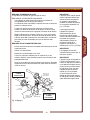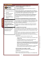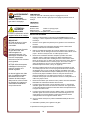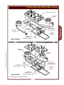
1
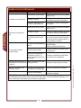
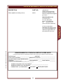
226
WELLS BLOOMFIELD, LLC
10 Sunnen Dr., St. Louis, MO 63143
telephone: 314-678-6314
fax: 314-781-2714
www.wellsbloomfield.com
OPERATION MANUAL
HEAVY DUTY GAS HOTPLATE
MODELS
HDHP1230G
HDSU1230G
HDHP2430G
HDSU2430G
HDHP3630G
HDSU3630G
Includes
INSTALLATION
USE & CARE
Model HDHP3630G
FOR YOUR SAFETY
Do not store gasoline or other flammable liquids
in the vicinity of this or any other appliance.
WARNING:
Improper installation, adjustment, alteration, service or maintenance can cause
property damage, injury or death. Read the installation, operating and maintenance instructions thoroughly before installing or servicing this equipment.
IMPORTANT:
The purchaser of this equipment must post in a prominent location instructions to be followed in the
event the user smells gas. This information shall be obtained by consulting the local gas supplier.
IMPORTANT: DO NOT DISCARD THIS MANUAL
This manual is considered to be part of the appliance and is to be given to the OWNER or
MANAGER of the restaurant, or to the person responsible for TRAINING OPERATORS of
this appliance. Additional manuals are available from your WELLS DEALER.
THIS MANUAL MUST BE READ AND UNDERSTOOD BY ALL PERSONS USING OR
INSTALLING THIS APPLIANCE. Contact your WELLS DEALER if you have any
questions concerning installation, operation or maintenance of this equipment.
p/n 2M-306627 Rev. F
M226
101109
LIMITED WARRANTY STATEMENT
ENGLISH
Unless otherwise specified, all commercial cooking
equipment manufactured by WELLS BLOOMFIELD, LLC is
warranted against defects in materials and workmanship for
a period of one year from the date of original installation or
18 months from the date of shipment from our factory,
whichever comes first, and is for the benefit of the original
purchaser only.
THIS WARRANTY IS THE COMPLETE AND ONLY
WARRANTY, EXPRESSED OR IMPLIED IN LAW OR IN
FACT, INCLUDING BUT NOT LIMITED TO, WARRANTIES
OF MERCHANTABILITY OR FITNESS FOR ANY
PARTICULAR PURPOSE, AND/OR FOR DIRECT,
INDIRECT OR CONSEQUENTIAL DAMAGES IN
CONNECTION WITH WELLS BLOOMFIELD PRODUCTS.
This warranty is void if it is determined that, upon inspection
by an authorized service agency, the equipment has been
modified, misused, misapplied, improperly installed, or
damaged in transit or by fire, flood or act of God. It also
does not apply if the serial nameplate has been removed, or
if service is performed by unauthorized personnel. The prices charged by Wells Bloomfield for its products are based
upon the limitations in this warranty. Seller’s obligation under this warranty is limited to the repair of defects without
charge by a Wells Bloomfield factory authorized service
agency or one of its sub-service agencies. This service will
be provided on customer’s premises for non-portable models. Portable models (a device with a cord and plug) must
be taken or shipped to the closest authorized service agency, transportation charges prepaid, for service. In addition to
restrictions contained in this warranty, specific limitations are
shown in the Service Policy and Procedure Guide. Wells
Bloomfield authorized service agencies are located in principal cities. This warranty is valid in the United States and
Canada and void elsewhere. Please consult your classified
telephone directory, your foodservice equipment dealer or
contact:
Service Department, Wells Bloomfield, LLC
10 Sunnen Dr., St. Louis, MO 63143
phone (314) 678-6314 or fax (314) 781-2714
for information and other details concerning warranty.
SERVICE POLICY AND PROCEDURE GUIDE and ADDITIONAL WARRANTY EXCLUSIONS
1.
2.
3.
4.
6.
cleaning schedules, are customer responsibility. Those
miscellaneous adjustments noted are customer
responsibility. Proper attention to preventative
maintenance and scheduled maintenance procedures
will prolong the life of the appliance.
7. Travel mileage is limited to sixty (60) miles from an
Authorized Service Agency or one of its sub-service
agencies.
8. All labor shall be performed during regular working
hours. Overtime premium will be charged to the buyer.
9. All genuine Wells replacement parts are warranted for
ninety (90) days from date of purchase on nonwarranty equipment. This parts warranty is limited only
to replacement of the defective part(s). Any use of
non-genuine Wells parts completely voids any
warranty.
10. Installation, labor, and job check-outs are not
considered warranty and are thus not covered by this
warranty.
11. Charges incurred by delays, waiting time or operating
restrictions that hinder the service technician’s ability to
perform service are not covered by warranty. This
includes institutional and correctional facilities.
SHIPPING DAMAGE CLAIM PROCEDURE
NOTE: For your protection, please note that equipment in
this shipment was carefully inspected and packaged by
skilled personnel before leaving the factory. Upon
acceptance of this shipment, the transportation company
assumes full responsibility for its safe delivery.
IF SHIPMENT ARRIVES DAMAGED:
1. VISIBLE LOSS OR DAMAGE: Be certain that any
visible loss or damage is noted on the freight bill or
express receipt, and that the note of loss or damage is
signed by the delivery person.
2. FILE CLAIM FOR DAMAGE IMMEDIATELY:
Regardless of the extent of the damage.
3.
CONCEALED LOSS OR DAMAGE: if damage is
unnoticed until the merchandise is unpacked, notify the
transportation company or carrier immediately, and file
“CONCEALED DAMAGE” claim with them. This
should be done within fifteen (15) days from the date
the delivery was made to you. Be sure to retain the
container for inspection.
Wells Bloomfield cannot assume liability for damage or loss
incurred in transit. We will, however, at your request, supply
you with the necessary documents to support your claim.
xi
226 306627 OpManual for HDHP-Series Hot Plates
5.
Resetting of safety thermostats, circuit breakers, over
load protectors, and/or fuse replacements are not
covered by this warranty unless warranted conditions
are the cause.
All problems due to operation at voltages or phase
other than specified on equipment nameplates are
not covered by this warranty.
Conversion to correct voltage and/or phase must be
the customer’s responsibility.
All problems due to electrical connections not made
in accordance with electrical code requirements
and wiring diagrams supplied with the equipment are
not covered by this warranty.
Replacement of items subject to normal wear, to
include such items as knobs, light bulbs; and, normal
maintenance functions including adjustments of
thermostats, adjustment of micro switches and
replacement of fuses and indicating lights are not
covered by warranty.
Damage to electrical cords and/or plug due to exposure
to excessive heat are not covered by this warranty.
Full use, care, and maintenance instructions supplied
with each machine. Noted maintenance and
preventative maintenance items, such as servicing and
ENGLISH
WARRANTY
SPECIFICATIONS
FEATURES & OPERATING CONTROLS
PRECAUTIONS & GENERAL INFORMATION
AGENCY LISTING INFORMATION
INSTALLATION
OPERATION
CLEANING INSTRUCTIONS
TROUBLESHOOTING SUGGESTIONS
PARTS & SERVICE
CUSTOMER SERVICE DATA
EXPLODED VIEW & PARTS LIST
ENGLISH
TABLE OF CONTENTS
xi
1
2
3
3
4
8
10
12
13
13
15
FRANÇAIS
DESCRIPTION ET AVERTISSEMENTS DE SÛRETÉ
SPÉCIFICATIONS
FONCTIONNALITÉS ET COMMANDES
PRÉCAUTIONS & RENSEIGNEMENTS D’ORDRE
GÉNÉRAL
INFORMATIONS CONCERNANT LES AGENCES
INSTALLATION
FONCTIONNEMENT
INSTRUCTIONS POUR LE NETTOYAGE
CONSEILS POUR LE DÉPANNAGE
16
17
18
19
19
20
24
26
28
INTRODUCTION
226 306627 OpManual for HDHP-Series Hot Plates
Thank You for purchasing this Wells Bloomfield appliance.
Proper installation, professional operation and consistent maintenance of this appliance will ensure that it
gives you the very best performance and a long, economical service life.
This manual contains the information needed to properly install this appliance, and to use and care for the
appliance in a manner which will ensure its optimum performance.
SPECIFICATIONS
MODEL
STYLE
HDHP1230G
HDSU1230G
2 Burners w/
Individual Control
HDHP2430G
HDSU2430G
4 Burners w/
Individual Control
HDHP3630G
HDSU3630G
6 Burners w/
Individual Control
FUEL
MANIFOLD
PRESSURE
Total B.T.U.
per HOUR
Natural Gas
5.0” W.C.
53,000
Propane (LP)
10” W.C.
44,670
Natural Gas
5.0” W.C.
106,000
Propane (LP)
10” W.C.
89,330
Natural Gas
5.0” W.C.
159,000
Propane (LP)
10” W.C.
134,000
1
FEATURES & OPERATING CONTROLS
ENGLISH
226 306627 OpManual for HDHP-Series Hot Plates
Fig. 1 Heavy Duty Hot Plate - Features & Operating Controls
2
This appliance is intended for use in commercial establishments
only.
This appliance is intended to prepare food for human consumption.
No other use is recommended or authorized by the manufacturer or its
agents.
This appliance must be installed by a technician qualified and certified
or licensed to install gas-fired equipment. A licensed technician must
perform the initial start-up and adjustment of the appliance.
Operators of this appliance must be familiar with the appliance use,
limitations and associated restrictions. Operating instructions must be
read and understood by all persons using or installing this appliance.
Cleanliness of this appliance is essential to good sanitation. Read and
follow all included cleaning instructions and schedules to ensure the
safety of the food product.
DO NOT submerge appliance or burners in water. This appliance is
not jet stream approved. DO NOT direct water jet or steam jet at this
appliance, or at any control. DO NOT splash or pour water on, in or
over any controls. DO NOT wash counter around this appliance with
water jet. Burners which have become wet must be thoroughly dried
before use.
WARNING:
FIRE HAZARD
All servicing of the gas
supply and combustion
components of this appliance
must be performed by a
technician trained and
certified in the maintenance
of gas appliances.
Improper servicing of gas
equipment can result in fire
and explosion.
CAUTION:
HOT SURFACE
Exposed surfaces can be hot
to the touch and may cause
burns.
Burner and grate surfaces will be very hot when in use. Contact will
cause severe injury.
This appliance must be operated with the supplied 4” legs properly
installed.
226 306627 OpManual for HDHP-Series Hot Plates
Do not operate this appliance if the smell of gas is present. Turn off
all gas supply valves and move to a remote location to call your
Authorized Wells Service Agent for service.
The technical content of this manual, including any parts breakdown
illustrations and/or adjustment procedures, is intended for use by qualified technical personnel only.
Any procedure which requires the use of tools must be performed by a
qualified technician.
This manual is considered to be a permanent part of the appliance.
This manual and all supplied instructions, diagrams, schematics, parts
breakdown illustrations, notices and labels must remain with the
appliance if it is sold or moved to another location.
AGENCY LISTING INFORMATION
This appliance conforms to NSF Standard 4 for sanitation only if
installed in accordance with the supplied Installation Instructions and
maintained according to the instructions in this manual.
This appliance meets ANSI Z.83.11 specifications for gas-fired food
service equipment.
This appliance is Canadian Standards Association design certified for
gas operation
3
STD 4
ENGLISH
PRECAUTIONS AND GENERAL INFORMATION
INSTALLATION
ENGLISH
NOTE: DO NOT discard
the carton or other packing
materials until you have
inspected the appliance for
hidden damage and tested it
for proper operation.
Refer to SHIPPING DAMAGE
CLAIM PROCEDURE on the
inside front cover of this
manual.
DANGER:
HEALTH
HAZARD
This appliance must be
properly ventilated. Failure to
provide and maintain proper
ventilation of exhaust gasses
can result in severe injury or
death.
UNPACKING & INSPECTION
Carefully remove the appliance from the carton. Remove all
protective plastic film, packing materials and accessories from the
appliance before connecting performing any installation procedure.
Carefully read all instructions in this manual and the Installation
Instruction Sheet packed with the appliance before starting any
installation.
Read and understand all labels and diagrams attached to the
appliance.
Carefully account for all components and accessories before
discarding packing materials. Store all accessories in a convenient
place for later use.
COMPONENTS
Cooking Grate (-1230G, 1 ea.; -2430G, 2 ea.;-3630G, 3 ea.)
Front Burner (-1230G, 1 ea.; -2430G, 2 ea.;-3630G, 3 ea.)
Rear Burner (-1230G, 1 ea.; -2430G, 2 ea.;-3630G, 3 ea.)
Adjustable Legs (set of 4)
Drip Tray, 1 ea.
SETUP
WARNING:
FIRE HAZARD
Do not store gasoline or
any other flammable or
combustible material near this
appliance. The open flame
can cause such materials to
ignite.
NOTICE: Manufacturer’s
warranty on this hotplate is in
effect only when the hotplate
is installed in accordance with
these instructions and local
codes and ordinances or, in
the absence of local codes,
the National Fuel Gas Code,
ANSI Z223.1 (current edition).
The manufacturer of this
hotplate assumes no liability
for any damage or injury
resulting from failure to
comply with this notice.
Verify local codes for requirements. Concrete, tile, terrazzo or metal
surfaces are recommended. Metal or tile over combustible material
may not meet code for non-combustible surfaces.
Clearances to non-combustible surfaces must be maintained.
Maintain 0” from side and rear to non-combustible walls, and 4” from
non-combustible counter as established by provided 4” legs.
Maintain adequate clearances for cleaning and proper operation.
The hotplate must be installed in an area with sufficient make-up air
for proper combustion, and must be installed such that the flow of
combustion and ventilation air will not be obstructed.
For servicing, Wells Mfg. recommends 6” clearance from rear of the
appliance to wall.
Install adjustable legs, one on each corner of
the appliance, in the holes provided. Verify
that the unit sits firmly ON ALL FOUR LEGS.
With the adjustable legs, adjust as required
to level the appliance. All four legs must be
adjusted to firmly contact the floor in order to
prevent tipping.
When used with an exhaust fan, special precautions must be
observed to avoid interference with the operation of the hotplate, such
as drafts and air starvation.
4
226 306627 OpManual for HDHP-Series Hot Plates
The area where the hotplate is
installed must be kept clear of
combustibles and flammables.
This includes mops, rags,
grease, wrapping paper and
electric cords.
This appliance is designed for use in non-combustible locations
only. Setup the hotplate only on a firm, level, non-combustible
surface.
GAS APPLIANCE CODE COMPLIANCE
DANGER:
The installation of gas piping from the outlet side of the gas meter or
service regulator to the hotplate must be performed by a technician
qualified and certified or licensed to install gas-fired equipment.
A licensed and qualified technician must perform the initial startup and
adjustment of this appliance.
The installation of this gas-fired appliance must conform to local codes,
or in the absence of such codes, with the current edition of
National Fuel Gas Code ANSI Z223.1.
For use in the State of Massachusetts, this appliance must be installed
in compliance with Massachusetts Fuel Gas and Plumbing Code
CMR 248.
The installation of this gas-fired appliance must comply with
applicable portions of NFPA 96 for ventilation. The current edition of
NFPA 96 (Standard for the Installation of Equipment for the Removal
of Smoke and Grease Laden Vapors from Commercial Cooking
Equipment) specifies ventilation requirements to ensure the removal
of exhaust gasses and products of combustion.
IT IS THE RESPONSIBILITY OF THE INSTALLER TO ENSURE
THAT THIS GAS HOTPLATE INSTALLATION CONFORMS TO ALL
APPLICABLE CODES AND ORDINANCES.
The venting of this appliance must not be obstructed, nor may such
venting interfere with the flow of combustion air required for proper
operation of the gas burners.
226 306627 OpManual for HDHP-Series Hot Plates
Additionally:
1. The gas supply line used to connect the hotplate to the gas
supply system must be black iron pipe, or other material as
approved by local ordinance for gas piping.
2. Gas supply piping must be inside 3/4” diameter or greater.
3. Use pipe sealant made specifically for gas piping on all pipe joints.
Apply sealant sparingly to the male threads only.
Sealant must be resistant to the action of LP gas.
4. Verify that all supply piping is clean and free of obstructions, dirt,
chips and pipe sealant compound prior to installation.
5. All pipe joints must be checked for leaks before lighting. Leak
checks should be performed with a soap and water solution.
NEVER CHECK FOR LEAKS WITH AN OPEN FLAME.
5
FIRE AND
EXPLOSION
HAZARD
NEVER use an open flame to
check for gas leaks. Fire and
explosion may result.
WARNING:
RISK OF INJURY
Installation procedures must
be performed by a qualified
technician with full knowledge
of all applicable gas-fired
appliance codes. Failure can
result in personal injury and
property damage.
IMPORTANT:
All pipe joints must be
checked for leaks before
lighting. Leak checks should
be performed with a soap and
water solution.
IMPORTANT:
Information on the
construction and installation
of ventilating hoods may be
obtained from the current
edition of NFPA 96
Standard for the Installation
of Equipment for the Removal
of Smoke and Grease Laden
Vapors from Commercial
Cooking Equipment.
Copies of this standard are
available from the
Nation Fire Protection Assn.:
NFPA
1 Batterymarch Park
P.O. Box 9101
Quincy, MA 02269-9101
ENGLISH
INSTALLATION (continued)
INSTALLATION (continued)
ENGLISH
DANGER:
FIRE AND
EXPLOSION
HAZARD
NEVER use an open flame to
check for gas leaks. Fire and
explosion may result.
IMPORTANT:
All pipe joints must be checked
for leaks before lighting. Leak
checks should be performed
with a soap and water solution.
WARNING:
FIRE HAZARD
This hotplate is supplied with a
gas pressure regulator.
Failure to properly install the
supplied regulator will result in
an extremely hazardous
condition.
Flow arrow stamped on body
of regulator must point toward
the hotplate.
Vent hole must point UP.
INSTALLING THE HOTPLATE
Refer to the nameplate. Verify the fuel type and pressure, which must
match the nameplate specifications. Connecting the hotplate to the
wrong fuel type and/or pressure will compromise the safety and/or
performance of the appliance.
The hotplate must be placed in its final operational position and
leveled front-to-back and side-to-side, with a spirit level, prior to
beginning the gas piping installation. Re-check the level of the unit
at the conclusion of the gas piping installation.
Each gas hotplate is supplied with a separate gas pressure
regulator, which must be installed on the manifold pipe protruding
from the rear of the hotplate. Ensure that the regulator is installed
such that the flow arrow stamped on the body of the regulator points
toward the hotplate. Failure to properly install the supplied regulator
will result in an extremely hazardous condition.
A moisture trap (drip leg) consisting of a tee, 4” nipple pointing down,
and cap must be installed upstream of the gas pressure regulator.
A manual gas shut-off valve may be required by local codes and is,
in any case, strongly recommended. The shut-off valve must be
installed between the gas supply piping and the gas pressure
regulator.
It is the responsibility of the gas piping installer to
identify the code requirement for a shut-off valve.
Shut-off valves, moisture trap and all associated piping must be
supplied by the gas piping installer.
IMPORTANT:
The appliance and its
individual manual shutoff valve
must be disconnected from
supply system piping during
any pressure testing of that
system at pressures in excess
of 1/2 p.s.i. (3.5 kPa).
Also, the appliance must be
isolated from the gas supply
piping system by closing its
individual manual shutoff valve
during any pressure testing of
the gas supply piping at test
pressures equal to or less than
1/2 p.s.i. (3.5 kPa).
VENT
SUPPLIED
REGULATOR
GAS
SHUT-OFF
VALVE*
DRIP LEG*
GAS
SUPPLY*
Fig. 2 Gas Supply Piping
6
* by others
226 306627 OpManual for HDHP-Series Hot Plates
IMPORTANT:
Verify fuel gas type. If the
available fuel does not match
the nameplate specification,
exchange the hotplate for the
correct type.
SET GAS PRESSURE:
Gas pressure regulator is factory set.
SET PILOT FLAME:
The pilot adjustments are located between the control valves for
each set of burners. The right valve controls the front pilot; the
left valve controls the rear pilot.
Using a small, flat-blade screwdriver, turn the screw clockwise to
decrease the flame size, or counter-clockwise to increase the
flame size.
Adjust the pilot flame to 1/4” high. Test for operation: inside and
outside sections of the burner must light without undue delay.
Drafty conditions may require a higher flame to allow the pilot to
remain lit.
ADJUST BURNER FLAME:
Remove all burner control knobs, then remove the front panel.
Turn an individual burner on. The right knob controls the front
burner; the left knob controls the rear burner.
Loosen the locking screw on the shutter.
Turn the shutter to admit more or less air as required. Adjust the
air shutter until the flame is mostly blue in color.
226 306627 OpManual for HDHP-Series Hot Plates
Tighten the locking screw when finished. Replace the front panel
and all knobs before returning the unit to service.
Fig. 3 Adjustments
7
IMPORTANT:
Adjustments must be performed
by a qualified technician only.
IMPORTANT:
This hotplate is shipped from
the factory equipped for either:
natural gas and adjusted for
sea level to 2000 feet elevation;
or, propane (LP) gas and
adjusted for sea level to 5000
feet elevation.
For operation other than listed
above, contact your Authorized
Wells Service Agency.
ENGLISH
INSTALLATION (continued)
OPERATION
ENGLISH
WARNING:
FIRE HAZARD
IF YOU SMELL GAS:
¤ DO NOT try to light
any appliance.
¤ DO NOT touch any
electrical switch
¤ DO NOT use any
telephone in your
building.
In the event a gas odor is
detected, shut down the
unit at the main gas
shutoff valve and contact
your local gas supplier
from a neighboring location.
Follow the instructions
received from the gas
supplier immediately
and exactly.
GENERAL OPERATIONAL NOTES
Carefully read the description of the hotplate operation on the
specification sheet.
Do NOT use this appliance if it has been submerged in water.
Call a qualified technician to examine the appliance and to service
or replace any component which has been submerged. Burners
which have been allowed to become wet must be thoroughly dried
before use.
For initial startup, and any time the gas supply has been shut-off, it
may take several minutes to light the pilot while air in the piping and
manifolds is purged.
The burner control knobs must be turned by hand only. Never use
tools to turn the control knob. If the knob will not turn by hand, do
NOT attempt to force or repair it. Contact your Authorized Wells
Service Agency for repairs. Forced or improperly repaired valves
pose the risk of fire and/or explosion.
Make sure burners, pilot burner and grate assembly are properly
installed before attempting to operate.
LIGHTING THE PILOT LIGHT
Before lighting the pilot light, smell all around the appliance area for
gas. Be sure to smell near floor level because some gas is heavier
than air and will settle to the floor.
For initial startup, and any time the gas supply has been shut-off, it
may take several minutes to light the pilot while air in the piping and
manifolds is purged.
SHUT DOWN INSTRUCTIONS
Turn all burner knobs to OFF.
Turn all pilots OFF.
Turn the main gas supply OFF.
8
226 306627 OpManual for HDHP-Series Hot Plates
The pilot light must be lighted by hand:
Turn both control knobs to the full OFF position.
Be sure the gas shut-off valve is ON and the appliance has had
time for the air to be purged from the lines.
Light the pilot with a long match or fireplace lighter. Use of a
cigarette lighter is NOT recommended.
OPERATION
WARNING:
Inspect the unit for cleanliness before use. Clean as necessary: See
Cleaning Instructions, page 11.
FIRE HAZARD
Be sure the pilot light is lit before operation. See Lighting the Pilot
Light, page 8.
The burner control knobs must be turned by hand only. Never use
tools to turn the control knob.
The control used in this gas hotplate provides a continuous range of
settings from OFF to ON.
The right knob controls the front burner
The left knob controls the rear burner
Light the burner by turning the control knob to the ON position until fire
forms completely around the inner and outer sections of the burner.
Set the control knob to the desired position. The setting can be
readjusted at any time.
NEVER attempt to force
or repair a stuck control
valve.
Contact your Authorized
Wells Service Agency for
repairs.
Forced or improperly
repaired valves pose the
risk of fire and/or
explosion.
WARNING:
FIRE AND
EXPLOSION
HAZARD
If the pilot light should be
extinguished, turn off the
gas shut-off valve and
remove the grate and drip
pan. Allow the appliance
to vent for five minutes
before attempting to
re-light.
Fig. 4 Burner Control
226 306627 OpManual for HDHP-Series Hot Plates
CAUTION:
HOT SURFACE
Cooking Recommendations:
Save energy by turning the temperature control knob OFF any time the
hotplate is not in use. Gas burners provide full heat instantly, making it
unnecessary to leave the unit on during intermittent use.
9
Exposed surfaces can be
hot to the touch and may
cause burns.
ENGLISH
OPERATION (continued)
CLEANING INSTRUCTIONS
ENGLISH
WARNING:
PREPARATION
FIRE HAZARD
Turn gas shut-off valve OFF before cleaning.
Allow hotplate to cool completely before cleaning.
Shut off the gas
supply valve before
cleaning.
CAUTION:
BURN HAZARD
Allow hotplate to
cool completely before
cleaning.
FREQUENCY
Daily
TOOLS
Bristle Brush
Clean Cloth or Sponge
Mild Detergent
Cleaner Formulated for Stainless Steel
Warm Water
CLEANING
IMPORTANT: DO NOT spill
or pour water into controls,
Turn gas shut-off valve OFF before cleaning.
DO NOT submerge hotplate
cabinet in water. Damage to
internal components will
occur.
Damage to internal
components from water
damage is NOT covered by
warranty.
Remove grate(s) and drip tray by lifting from cabinet.
Allow hotplate to cool completely before cleaning.
Note position of front and rear burner assemblies in cabinet. Remove
burner assemblies.
Clean food particles from grate drip tray with warm water, mild
detergent and a bristle brush. Rinse with clean water. Wipe dry
with a soft clean cloth.
Good sanitation is vital to the
quality of the final food
product. Be sure to clean in
all corners and crevices
where grease and other
cooking debris can
accumulate.
Wipe the outer portions of the hotplate cabinet with a clean soft cloth or
sponge dampened with warm water and a mild detergent or cleaner
formulated for cleaning stainless steel. DO NOT use steel wool to
clean hotplate cabinet. Rinse by wiping hotplate cabinet with a clean
soft cloth or sponge moistened with clean warm water. Dry cabinet by
wiping with a clean soft dry cloth.
Examine burners to be sure the air shutters are in their proper position.
Reinstall burner assemblies in cabinet (see fig. 5, page 11):
Burner with short venturi tube is the front burner. The venturi / air
shutter slides over the nozzle of the right control valve. The pegs
on the bottom of the burner set in corresponding notches at the
front of the burner support bracket.
Burner with long venturi tube is the rear burner. The venturi / air
shutter slides over the nozzle of the left control valve. The pegs
on the bottom of the burner set in corresponding notches at the
rear of the burner support bracket.
Turn shut-off valve ON and light pilot light.
Reinstall drip tray and grate.
Procedure is complete.
10
226 306627 OpManual for HDHP-Series Hot Plates
DO NOT steel wool or
metal scouring pads to clean
cabinet, drip tray or crumb
tray.
Examine burner assemblies. Note position of air shutters before
cleaning. Clean food particles from burners with warm water, mild
detergent and a bristle brush. Rinse by wiping with a soft cloth
dampened with clean water. Wipe exterior surfaces dry with a soft
clean cloth. Allow burners to air dry so that interior passages are
completely free of water.
COOKING GRATE
FRONT
BURNER
BURNER
SUPPORT
BRACKET
REAR
BURNER
FRONT BURNER
CONTROL VALVE
DRIP TRAY
HDHP-SERIES
REAR BURNER
CONTROL VALVE
COOKING GRATES
226 306627 OpManual for HDHP-Series Hot Plates
REAR
BURNER
FRONT
BURNER
FRONT BURNER
CONTROL VALVE
BURNER
SUPPORT
BRACKETS
DRIP TRAY
HDSU-SERIES
REAR BURNER
CONTROL VALVE
Fig. 5 Hotplate Assembly
11
ENGLISH
CLEANING INSTRUCTIONS (continued)
TROUBLESHOOTING
ENGLISH
SYMPTOM
POSSIBLE CAUSE
SUGGESTED REMEDY
Pilot will not light
Gas supply off
Check main / unit gas valves
Air in lines
Turn pilot valve on. Attempt to
light pilot every 15 sec.
Pilot valve not on
Turn pilot valve on / adjust
Gas supply off
Check main / unit gas valves
Air in lines
Turn gas valve on. Attempt to
light pilot every 15 sec.
Pilot valve not lit
Turn off gas - allow unit to
vent for 5 minutes. Turn gas
back on and light pilot
Control not on
Turn temperature control to ON
Set to desired setting when lit
Water in burner
Remove burner and dry
thoroughly
Damaged temperature control,
Burner or other internal
component
Contact Authorized Wells
Service Agency for repairs
Temperature control not set
Adjust for desired temperature
Shutter or nozzle out of
adjustment
Contact qualified technician for
adjustment
Damaged temperature control,
burner or other internal
component
Contact Authorized Wells
Service Agency for repairs
Burners won’t light
Front or rear burner
won’t light
Burner not hot enough
12
226 306627 OpManual for HDHP-Series Hot Plates
NOTE: There are no user
serviceable components in the
burner assemblies or in the control valves. In all cases of damage or malfunction,
contact your Authorized Wells
Service Agency for repairs.
DESCRIPTION
PART NO.
LEGS, ADJUSTABLE 4” METAL (SET of 4)
5D-20563
IMPORTANT: Use only
factory authorized service
parts and replacement
filters.
For factory authorized
service, or to order factory
authorized replacement parts,
contact your Wells authorized
service agency, or call:
Wells Bloomfield, LLC
10 Sunnen Dr.
St. Louis, MO 63143
Service Parts Dept.
phone: (888) 356-5362
fax:
(314) 781-2714
226 306627 OpManual for HDHP-Series Hot Plates
Service Parts Department can
supply you with the name and
telephone number of the
WELLS AUTHORIZED
SERVICE AGENCY
nearest you.
CUSTOMER SERVICE DATA
please have this information available if calling for service
RESTAURANT _____________________________ LOCATION _____________
INSTALLATION DATE ________________________ TECHNICIAN ___________
SERVICE COMPANY ________________________________________________
ADDRESS ___________________________ STATE ______ ZIP__________
TELEPHONE NUMBER (_____)_____-_________
EQUIPMENT MODEL NO. _______________
EQUIPMENT SERIAL NO. _______________
FUEL (check one)
NATURAL GAS
13
PROPANE / LP
ENGLISH
PARTS & SERVICE
NOTES
ENGLISH
226 306627 OpManual for HDHP-Series Hot Plates
14
ENGLISH
EXPLODED VIEW & PARTS LIST
PLATE SHELF
HDHP2430GPS
I7-WL0595
COOKING GRATE
DD-23221
REGULATOR
CONVERTIBLE
FOR LP OR NAT
2J-306629
BURNER ASSY, REAR
WS-507165
BURNER ASSY, FRONT
WS-507164
PILOT BURNER ASSY
(CUT TO LENGTH)
WS-507188
226 306627 OpManual for HDHP-Series Hot Plates
ORIFICE HOOD (ONLY)
SEE CONVERSION CHART
FOR LP / PROPANE and/or
OPERATION ABOVE 3000’
ELEVATION
PILOT ADJUST, DUAL
WS-506632
PILOT ADJUST, SINGLE
2K-39315
AIR SHUTTER, VENTURI
2F-506637
LOCKING SCREW, SHUTTER
2C-70813
GAS CONTROL VALVE ASSY
(NAT ORIFICE - SEA LEVEL
TO 5000’) WS-506631
CONTROL KNOB
WS-507160
DRIP TRAY
WS-507170 (HDHP1230)
WS-507171 (HDHP2430)
WS-507172 (HDHP3630)
LEG, 4” METAL
WS-507177
IL2074b
HDHP-SERIES HEAVY DUTY HOTPLATE
15
MANUEL DE L’UTILISATEUR
DE LA PLAQUE CHAUFFANTE PROFESSIONNELLE AU GAZ WELLS
MODÈLES
HDHP1230G, HDSU1230G
HDHP2430G, HDSU2430G
HDHP3630G, HDSU3630G
FRANÇAIS
Modéle
HDHP3630G
Comprend :
INSTALLATION,
MODE D’EMPLOI & ENTRETIEN
POUR VOTRE SÉCURITÉ
Ne pas stocker d’essence ou d'autres liquides inflammables au voisinage de cet
appareil ou autres appareils ménagers.
IMPORTANT :
L’acquéreur de ce matériel doit afficher, en pleine vue du public, les instructions à
suivre en cas de détection d’une odeur de gaz par l’utilisateur. Cette information
doit être obtenue après consultation de la société locale distributrice du gaz.
IMPORTANT : NE PAS JETER CE GUIDE
Ce guide fait partie de l’appareil et doit être remis au propriétaire, au directeur du
restaurant ou à la personne responsable de la formation des utilisateurs de l’appareil.
Des guides supplémentaires sont disponibles chez votre distributeur Wells.
Ce guide doit être lu et compris par toutes personnes installant ou utilisant cet appareil.
Contacter votre distributeur Wells pour toutes questions au sujet de l’installation, du
fonctionnement ou de l’entretien de cet appareil.
16
226 306627 OpManual for HDHP-Series Hot Plates
AVERTISSEMENT !
L’installation, le réglage, les modifications, l’entretien ou la maintenance effectués
de manière incorrecte peuvent entraîner des dommages matériels, corporels ou même
la mort. Lire attentivement les instructions relatives à l’installation, au fonctionnement,
à l’entretien et à la maintenance avant d’installer ou de réparer l’équipement.
TABLE DES MATIÈRES
FRANÇAIS
DESCRIPTION ET AVERTISSEMENTS DE SÛRETÉ
SPÉCIFICATIONS
FONCTIONNALITÉS ET COMMANDES
PRÉCAUTIONS & RENSEIGNEMENTS D’ORDRE
GÉNÉRAL
INFORMATIONS CONCERNANT LES AGENCES
INSTALLATION
FONCTIONNEMENT
INSTRUCTIONS POUR LE NETTOYAGE
CONSEILS POUR LE DÉPANNAGE
14
15
16
17
17
18
22
24
26
Merci d’avoir acquis cet appareil Wells Bloomfield. L’installation correcte, le fonctionnement professionnel
et l’entretien régulier de cet appareil assureront ses meilleures performances et sa longue durée de
service aux meilleurs coûts. Le présent manuel contient l’information nécessaire pour installer
correctement l’appareil et pour l’utiliser et l’entretenir de manière à ce qu’il fonctionne avec des
performances optimales.
226 306627 OpManual for HDHP-Series Hot Plates
SPÉCIFICATIONS
CONSOMMATION
D’ÉNERGIE
TOTALE (BTU) par
heure
MODÈLE
STYLE
COMBUSTIBLE
PRESSION DU
COLLECTEUR
HDHP1230G
HDSU1230G
2 brûleurs avec
commandes
individuelles
Gaz naturel
5.0” W.C.
53,000
Propane*
10” W.C.
43,000
HDHP2430G
HDSU2430G
4 brûleurs avec
commandes
individuelles
Gaz naturel
5.0” W.C.
106,000
Propane*
10” W.C.
86,000
HDHP3630G
HDSU3630G
6 brûleurs avec
commandes
individuelles
Gaz naturel
5.0” W.C.
159,000
Propane*
10” W.C.
129,000
*Propane (gaz de pétrole liquide--GPL)
17
FRANÇAIS
INTRODUCTION
FONCTIONNALITÉS ET COMMANDES
GRILLE DE CUISSON
FRANÇAIS
BRÛLEUR ARRIÈRE
BRÛLEUR
AVANT
PLATEAU
POUR LA
GRAISSE
BRÛLEURS
DE
VEILLEUSES
D'ALLUMAGE
COMMANDE
DU BRÛLEUR
AVANT
COMMANDE
DU BRÛLEUR
ARRIÈREL
PIEDS
RÉGLABLES
18
226 306627 OpManual for HDHP-Series Hot Plates
Fig. 6 Foncionnalites et Commandes se la Plaque Chauffante Professionelle á Gaz
PRÉCAUTIONS & RENSEIGNEMENTS D’ORDRE GÉNÉRAL
226 306627 OpManual for HDHP-Series Hot Plates
NE PAS submerger l’appareil ou les brûleurs dans l’eau. Cet appareil
n’est pas approuvé pour supporter les jets d’eau. NE PAS orienter
de jet d’eau ou de vapeur directement sur cet appareil ou de ses
commandes. NE PAS éclabousser ni verser d’eau sur, dans ou par
dessus les commandes. NE PAS laver le comptoir entourant l’appareil
avec un jet d’eau. Les brûleurs mouillés doivent être complètement
séchés avant usage.
Les surfaces de cuisson deviennent très chaudes pendant l’usage.
Leur contact provoquera des brûlures graves.
Cet appareil doit être utilisé avec ses pieds de 10 cm (4 po.) de haut
correctement installés.
Ne pas utiliser cet appareil en présence d’une odeur de gaz. Fermer
tous les robinets à gaz et se rendre dans un lieu éloigné pour appeler
un technicien d’entretien agréé par Wells.
La partie technique du présent manuel, y compris tous les schémas
éclatés illustrant les pièces et/ou les procédures de réglage, est
destinée exclusivement à l’usage de techniciens qualifiés.
Toute procédure exigeant l’emploi d’outils doit être accomplie par un
technicien qualifié.
Le présent manuel est considéré être une pièce permanente de
l’appareil. Ce manuel et toutes les instructions, schémas, illustrations
de pièces éclatées, notices et étiquettes fournis doivent demeurer avec
l’appareil si ce dernier est revendu ou déménagé dans un autre local.
AVERTISSEMENT!
DANGER D’INCENDIE
Toutes les opérations
d’entretien et de réparation
des composants servant à
l’alimentation et à la
combustion du gaz dans cet
appareil doivent être
effectuées par un technicien
qualifié et agréé pour la
maintenance des appareils
à gaz. L’entretien incorrect
des appareils à gaz peut
entraîner des incendies et
des explosions.
ATTENTION:
SURFACE CHAUDE
Les surfaces exposées
peuvent être chaudes au
toucher et peuvent
occasionner des brûlures.
INFORMATIONS CONCERNANT LES AGENCES
Cet appareil n’est conforme à la Norme 4 de la fondation nationale de
normalisation sanitaire des États-Unis (National Sanitation Foundation-NSF) que s’il est installé conformément aux Instructions relatives à
l’installation fournies avec l’appareil et si ce dernier est entretenu selon
les instructions du présent manuel.
Cet appareil est conforme aux spécifications ANSI Z.83.11 pour les
appareils à gaz utilisés dans les établissements préparant des
aliments.
Cet appareil est d’une conception certifiée pour le fonctionnement au
gaz par l’Association canadienne de normalisation (ACN/CSA).
19
Norme 4
FRANÇAIS
Cet appareil est prévu exclusivement à l’usage des
établissements commerciaux.
Cet appareil est destiné à la cuisson d’aliments pour la consommation
humaine. Aucun autre usage n’est recommandé ni autorisé par le
fabricant ou ses agents.
Cet appareil doit être installé par un technicien qualifié ou et certifié
ou agréé pour l’installation des équipements fonctionnant au gaz. Un
technicien qualifié et agréé doit assurer la mise en service et le réglage
initiaux de l'appareil.
Les utilisateurs de l’appareil doivent être familiarisés avec l’utilisation
de l’appareil, ses limites et ses restrictions associées. Le mode
d’emploi doit être lu et compris par toutes les personnes installant ou
utilisant cet appareil.
La propreté de cet appareil est essentielle à de bonnes conditions sanitaires. Lire et suivre toutes les instructions relatives au nettoyage et
aux programmes visant à assurer l’innocuité des produits alimentaires.
L'INSTALLATION
REMARQUE : NE PAS jeter le
carton ni les autres matériaux
d’emballage jusqu’à ce que
l’appareil ait été inspecté pour la
détection de vices cachés et ait
subi des tests de fonctionnement
satisfaisants. Consulter la
PROCÉDURE DE RÉCLAMATION EN CAS DE DOMMAGES
DUS AU TRANSPORT imprimée
sur la face interne de la première
page de couverture du présent
manuel.
DANGER:
FRANÇAIS
Danger pour la
santé
Cet appareil doit être situé dans
un local correctement aéré. Le
défaut d’assurance et de maintien
d’une aération convenable avec
mise à l’évent des gaz de
combustion peut entraîner des
dommages corporels graves ou
même la mort.
AVERTISSEMENT :
Danger d’incendie
Ne pas stocker
NOTICE : La garantie du
fabricant concernant cet appareil
entre en vigueur exclusivement si
l’appareil est installé
conformément aux présentes
instructions, aux dispositions de
la réglementation et des codes
locaux, ou en l’absence de codes,
de la norme ANSI Z223.1 (édition
en vigueur) du code national
relatif au gaz combustible
(National Fuel Gas Code). Le
fabricant de ce grill décline toute
responsabilité en cas de
dommages corporels ou matériels
résultant du défaut d'application
des dispositions de la présente
notice.
Sortir l’appareil du carton avec précaution. Enlever tous les films de
protection en plastique, les matériaux d’emballage et les accessoires
de l’appareil avant d'entamer toute procédure d'installation et de connexion.
Lire attentivement toutes les instructions du présent manuel et de la
Notice-–Instructions relatives à l’installation, incluse avec l’appareil,
avant de commencer l’installation.
Lire et assimiler la signification de toutes les étiquettes et schémas
fixés sur l’appareil.
Vérifier que tous les composants et accessoires sont présents avant de
jeter les matériaux d'emballage. Ranger tous les accessoires dans un
lieu convenable pour les utiliser plus tard.
COMPOSANTS
Grille de cuisson (-1230G, 1 pièce; -2430G, 2 pièce; -3630G, 3 pièce)
Brûleur avant (-1230G, 1 pièce; -2430G, 2 pièce; -3630G, 3 pièce)
Brûleur arrière (-1230G, 1 pièce; -2430G, 2 pièce; -3630G, 3 pièce)
Pieds réglables, (jeu de 4)
Plateau pour la graisse, 1 pour chaque
INSTALLATION
Installer l’appareil uniquement sur une surface solide, horizontale et
non combustible. Vérifier les conditions imposées par les codes locaux.
Les surfaces en ciment, en carreaux de céramique ou de marbre, ou
en métal sont recommandées. Le métal ou les carreaux de céramique
posés sur des matériaux combustibles peuvent
FIXATION PAR
être incompatibles avec les dispositions du
VIS DANS LE
code imposant des surfaces non combustibles.
CADRE
Installer les pieds fournis avec l’appareil,
un pied à chaque coin de l’appareil, dans
les trous préparés. Vérifier que l’unité est
stable et repose bien SUR LES QUATRE
PIEDS. Les pieds étant réglables, les ajuster
selon les besoins pour que l’appareil soit
horizontal. Les quatre pieds doivent être
ajustés pour faire solidement contact avec
le comptoir afin d’éviter tout basculement.
TOURNER
POUR
RÉGLER
LA HAUTEUR
Ménager des dégagements adéquats dans l’armoire pour les orifices
d’aération. Consulter la Notice—Intructions relatives à l’installation,
pour obtenir les dimensions de dégagement obligatoires. Conserver
les distances de dégagement nécessaires entre l’appareil et les
surfaces combustibles adjacentes.
L’appareil doit être installé dans un lieu où l’air est suffisamment
renouvelé pour assurer une combustion correcte et de telle manière
que le courant de l’air de combustion et d’aération ne soit pas obstrué .
Lorsqu’on utilise l’appareil avec un ventilateur d’extraction, il faut
prendre des précautions spéciales pour éviter toute interférence avec
le fonctionnement de l’appareil, tels que courants d’air et privation
d’air .
20
226 306627 OpManual for HDHP-Series Hot Plates
d’essence ou d'autres matériaux
combustibles ou
inflammables à proximité de cet
appareil. Toute flamme nue peut
provoquer l’inflammation de ces
matériaux. La zone où le grill est
installé doit être dépourvue de
tout matériau combustible ou
inflammable. Ceux-ci
comprennent, notamment, les
serpillères, les lavettes ou les
chiffons, la graisse, le papier
d’emballage et les cordons
d’alimentation électriques.
DÉBALLAGE & INSPECTION
L'INSTALLATION (a continué)
L’installation des tuyauteries du gaz entre le côté sortie du compteur à
gaz ou du régulateur de l’alimentation publique et l’appareil doit être
effectuée par un technicien qualifié et certifié ou agréé pour l’installation
des appareils à gaz.
Un technicien qualifié et agréé doit assurer la mise en service et le
réglage initiaux de l'appareil.
L’installation de cet appareil à gaz doit être conforme aux codes locaux,
ou en l’absence de codes, à l’édition en vigueur de la norme ANSI
Z223.1 du Code national applicable au gaz combustible (National Fuel
Gas Code—NFGC).
Pour l'usage dans l'Etat de Massachusetts, cet appareil doit être installé
en conformité avec le Massachusetts Fuel Gas and Plumbing Code
CMR 248.
L’installation de cet appareil à gaz doit être conforme aux parties
applicables de la norme NFPA 96 relatives à l’aération. L’édition
courante de la norme NFPA 96 précise les conditions obligatoires à
remplir pour l'extraction des gaz et des produits de combustion.
L’INSTALLATEUR EST RESPONSABLE D’ASSURER QUE
L’INSTALLATION DE CE GRILL À GAZ SOIT CONFORME À TOUS
LES CODES ET À TOUTE RÉGLEMENTATION APPLICABLES.
La mise à l’évent de cet appareil ne doit pas être obstruée, et cette
mise à l’évent ne doit en aucun cas interférer avec le courant de l’air
de combustion exigé pour le fonctionnement correct des brûleurs à gaz.
226 306627 OpManual for HDHP-Series Hot Plates
En outre :
1. La ligne d’alimentation de gaz utilisée pour raccorder le grill au
système d’alimentation de gaz doit être un tuyau en acier non
revêtu (fer noir) ou autre matériau approuvé par la réglementation
locale applicable aux tuyauteries de gaz.
2. La tuyauterie du gaz doit avoir un diamètre intérieur égal ou
supérieur à ¾ po. (1,9 cm).
3. Utiliser un mastic pour l’étanchéité des raccords de tuyauterie,
spécial pour les tuyauteries à gaz, sur tous les raccords de
tuyauterie. Appliquer le mastic en petite quantité uniquement sur
les filetages mâles.
Le mastic doit être résistant à l'action du gaz GPL.
4. Vérifier que toute la tuyauterie d’alimentation de gaz est propre et
épourvue de toute obstruction, saleté, débris et particules de mastic
d'étanchéité avant l’installation .
5. Tous les raccords de tuyauterie doivent être inspectés pour la
détection de fuites éventuelles avant l’allumage. Détecter les fuites
avec une solution d’eau savonneuse. NE JAMAIS DÉTECTER DE
FUITES AVEC UNE FLAMME NUE .
21
DANGER :
DANGER
D’INCENDIE ET
D’EXPLOSION
NE JAMAIS utiliser de
flamme nue pour détecter des
fuites de gaz. Un incendie et
une explosion pourrait se
produire.
AVERTISSEMENT :
DANGER DE DOMMAGE CORPOREL
Les procédures d’installation
doivent être accomplies par
un technicien qualifié ayant
pleine connaissance des
dispositions des codes en
vigueur relatives aux
appareils à gaz. À défaut, des
dommages corporels et
matériels peuvent survenir.
IMPORTANT : Tous les raccords
de tuyauterie doivent être
inspectés pour la détection de
fuites éventuelles avant
l’allumage. Détecter les fuites
avec une solution d’eau
savonneuse.
IMPORTANT : L’information
relative à la construction et
l’installation des hottes d’aération
doit être obtenue dans l’édition
en vigueur de la norme NFPA 96
Standard for the Installation of
Equipment for the Removal of
Smoke and Grease Laden apors
from Commercial Cooking Equipment. (Norme relative à l’installation d’équipements destinés à
l’extraction des fumées et des
vapeurs chargées de graisse
générées par les appareils de
cuisson commerciaux.)
Des exemplaires de cette norme
sont disponibles auprès de
l’Association nationale pour la
protection contre les incendies
(National Fire Protection
Association—NFPA)
NFPA
1 Batterymarch Park
P.O. Box 9101
Quincy, MA 02269-9101
FRANÇAIS
CONFORMITÉ AU CODE RELATIF AUX APPAREILS À GAZ
L'INSTALLATION (a continué)
DANGER :
DANGER
D’INCENDIE ET
D’EXPLOSION
NE JAMAIS utiliser de flamme
nue pour détecter des fuites de
gaz. Un incendie et une
explosion pourrait se produire.
FRANÇAIS
IMPORTANT :
Tous les raccords de
tuyauterie doivent être
inspectés pour la détection de
fuites éventuelles avant
l’allumage. Détecter les fuites
avec une solution d’eau
savonneuse .
AVERTISSEMENT :
DANGER
D’INCENDIE
Cet appareil à gaz est vendu
avec un régulateur de
pression. Le défaut
d’installation correcte du
régulateur de pression crée
une situation extrêmement
dangereuse. La flèche gravée
sur le corps du régulateur doit
pointer vers le grill. Le trou
d’aération doit pointer vers le
HAUT.
Consulter la plaque signalétique. Vérifier la nature et la pression du combustible, qui doivent correspondre aux spécifications indiquées sur la plaque signalétique. Le raccordement de l’appareil à une
alimentation en combustible incorrecte ou sous pression incorrecte compromettrait la sécurité et/ou les performances de l’appareil.
VÉRIFIER QUE LES DISTANCES DE DÉGAGEMENT OBLIGATOIRES PAR
RAPPORT AUX SURFACES COMBUSTIBLES SONT
RESPECTÉES.
L’appareil doit être mis en place dans sa position de fonctionnement
définitive et mis à niveau horizontalement (l’arrière par rapport au devant, un
côté par rapport à l’autre) à l’aide d’un niveau à bulle, avant de
commencer l’installation de la tuyauterie du gaz.
Vérifier de nouveau le niveau horizontal de l’unité après l’installation de la
tuyauterie du gaz.
Chaque appareil à gaz est vendu avec un régulateur de pression séparé, qui
doit être installé sur le tuyau du collecteur dépassant à l’arrière de l’appareil.
Vérifier que le régulateur est installé de manière à ce que la flèche indiquant le
débit, gravée sur le corps du régulateur, pointe vers le grill. Le défaut
d’installation correcte du régulateur de pression crée une situation
extrêmement dangereuse.
Un purgeur de condensat (collecteur de condensat) comportant un Té, un
mamelon de 4 po. (10 cm) pointant vers le bas et un capuchon doit être
installé en amont du régulateur de pression de gaz .
Un robinet d’arrêt de gaz manuel peut être exigé par les codes locaux et son
installation est fortement recommandée dans tous les cas. Le robinet d’arrêt
doit être installé entre la tuyauterie d’alimentation de gaz et le régulateur de
pression .
ÉVENT
RÉGULATEUR
FOURNI AVEC
L'APPAREIL
AR
RIÈ
ROBINET
D'ARRÊT
DU GAZ *
RE
DU
NSANT
E
S UR
CO
DU
GR
ILL
PURGEUR DE
CONDENSAT *
ALIMENTATION
DE GAZ *
* par des tiers
Fig. 7 Tuyauterie d’alimentation du gaz
L’installateur de la tuyauterie du gaz est responsable d’identifier les dispositions
obligatoires du code relatives aux robinets d'arrêt de gaz .
Les robinets d’arrêt, le purgeur de condensat et toute la tuyauterie associée
doivent être fournis par l’installateur de la tuyauterie du gaz.
22
226 306627 OpManual for HDHP-Series Hot Plates
IMPORTANT :
Vérifier la nature du gaz
combustible. Si le combustible
disponible ne correspond pas
aux spécifications de la plaque
signalétique, échanger
l’appareil contre un autre, de
type correct.
INSTALLATION DU GRILL À GAZ
L'INSTALLATION (a continué)
RÉGLAGE DE LA VEILLEUSE D’ALLUMAGE :
Les réglages de veilleuse sont situés entre les robinets de
commande de chacun des jeux de brûleurs.
Le robinet de droite commande la veilleuse avant et le robinet de
gauche la veilleuse arrière.
À l’aide d’un petit tournevis plat, tourner la vis dans le sens
horaire pour diminuer la hauteur de la flamme ou dans le sens
inverse au sens horaire pour augmenter la hauteur de la flamme.
Régler la flamme de la veilleuse à 0,64 cm (1/4 po.) de hauteur.
Essai de fonctionnement : toutes les sections de brûleur doivent
s’allumer sans délai. Dans les lieux à courants d’air, une flamme
plus haute peut être nécessaire pour que la veilleuse reste
allumée.
RÉGLAGE DE LA FLAMME DE BRÛLEUR :
Enlever tous les boutons de commande des brûleurs puis enlever
le panneau avant.
Allumer l’un des brûleurs.
Desserrer la vis de blocage sur le volet.
Tourner le volet pour admettre plus ou moins d’air, le cas
échéant. Régler le volet d’aération jusqu’à ce que la flamme soit
principalement bleue.
L'AJUSTEMENT DE
FLAMME
DE BRULEUR
RÉGLAGE DE
LA VEILLEUSE
D'ALLUMAGE
MOINS
D'AIR
OFF
VOLET
ON
PLUS D'AIR
ON
VIS DE
BLOCAGE
OFF
226 306627 OpManual for HDHP-Series Hot Plates
Serrer la vis de blocage quand l’opération est terminée. Remettre
le panneau avant et tous les boutons en place avant de remettre
l’unité en service .
BOUTON DE
COMMANDE
DU BRÛLEUR
OUVERTURE
FERMETURE
FLAMME
PLUS
PETITE
FLAMME
PLUS
GRANDE
L'AJUSTEMENT DE
FLAMME
D'ALLUMAGE
Fig. 8 Réglages
23
IMPORTANT :
L’appareil et son robinet d’arrêt
manuel individuel doivent être
déconnectés de la tuyauterie
du système d’alimentation
pendant les essais de pression
de ce système dépassant 1/2
p.s.i. (3,5 kPa).
Il faut également isoler
l’appareil du système
d’alimentation de gaz en
fermant son robinet d’arrêt
manuel individuel pendant tous
les essais de tuyauterie
d’alimentation lorsque les
pressions d’essai de la
tuyauterie sont égales ou
inférieures à 1/2 p.s.i. (3,5 kPa).
IMPORTANT:
Les réglages doivent être
exécutés exclusivement par un
technicien qualifié.
IMPORTANT:
L’appareil à gaz est expédié de
l’usine tout équipé pour le gaz
naturel et réglé pour fonctionner
à une altitude comprise entre le
niveau de la mer et 660 mètres
(2 000 pieds). Pour convertir
l’appareil au gaz de pétrole
liquide (LP) ou au propane,
ou pour fonctionner à une
altitude de plus de 660 mètres
(2 000 pieds), veuillez contacter
votre distributeur agréé Wells.
FRANÇAIS
RÉGLAGE DE PRESSION DU GAZ :
Le régulateur de pression du gaz est réglé en usine .
FONCTIONNEMENT
AVERTISSEMENT:
DANGER
D’INCENDIE
SI VOUS SENTEZ LE GAZ:
¤ NE PAS tenter d’allumer
l’appareil.
¤ NE toucher à AUCUN
bouton électrique.
¤ NE PAS utiliser le
téléphone situé dans le
bâtiment.
FRANÇAIS
Si l’on détecte une odeur de
gaz, mettre l’unité à l’arrêt en
fermant le robinet d’arrêt
principal du gaz et contacter la
société responsable de
l’alimentation en gaz à partir
d’un poste téléphonique du
voisinage.
Suivre immédiatement et
exactement les instructions
fournies par la société
distributrice du gaz .
COMMENTAIRES D’ORDRE GÉNÉRAL SUR
LE FONCTIONNEMENT
Lire attentivement la description du fonctionnement du grill sur
la notice de spécifications.
NE PAS utiliser l’appareil s’il a été immergé dans l'eau. Appeler un
technicien qualifié pour examiner l’appareil et le réparer ou remplacer
tout composant ayant été submergé. Les brûleurs qui ont pu être
mouillés doivent être complètement séchés avant usage.
Pour la mise en route initiale, et chaque fois que l’alimentation de
gaz a été coupée, il pourra falloir plusieurs minutes pour allumer
la veilleuse pendant que l’air est purgé de la tuyauterie et des
collecteurs.
Les boutons de commande des brûleurs ne doivent être tournés
qu’à la main. Ne jamais utiliser d’outil pour tourner les boutons.
Si un bouton ne tourne pas à la main, NE PAS essayer de le forcer
ni de le réparer. Pour toute réparation, contacter le distributeur agréé
Wells. Les boutons ou robinets forcés ou mal réparés posent un
risque d’incendie et/ou d’explosion.
S’assurer que les brûleurs, le brûleur de la veilleuse et le plateau
à graisse sont correctement installés avant d’essayer la mise en
marche.
ALLUMAGE DE LA VEILLEUSE
Avant d’allumer la veilleuse, sentir l’atmosphère autour de l’appareil
pour détecter toute trace de gaz. Ne pas oublier de sentir près du sol
parce que le gaz est plus lourd que l’air et s’accumulerait au niveau
du sol.
Pour la mise en route initiale, et chaque fois que l’alimentation de gaz
a été coupée, il pourra falloir plusieurs minutes pour allumer la
flamme de la veilleuse pendant que l’air est purgé de la tuyauterie et
des collecteurs.
Tourner tous les boutons de commande jusqu’à la positions OFF
(FERMETURE).
La veilleuse est adjacente à l’un des pieds de brûleur et est
accessible à travers l’ouverture du panneau avant .
S’assurer que le robinet d’arrêt du gaz est sur ON (OUVERTURE)
et que l’air a eu le temps d’être purgé des lignes de gaz. Essayer
d’allumer la flamme de la veilleuse toutes les 15 secondes après
avoir ouvert le robinet d’arrêt du gaz .
Allumer la veilleuse avec une longue allumette ou un briquet pour
feu de cheminée. NE PAS utiliser de briquet pour cigarette.
INSTRUCTIONS POUR LA MISE À L’ARRÊT
Tourner tous les boutons de brûleur jusqu’à la position OFF
(FERMETURE).
Éteindre toutes les veilleuses d’allumage .
Mettre le robinet d’arrêt général sur la position OFF (FERMETURE).
24
226 306627 OpManual for HDHP-Series Hot Plates
La flamme de la veilleuse doit être allumée à la main :
FONCTIONNEMENT (a continué)
FONCTIONNEMENT DE LA PLAQUE CHAUFFANTE
AVERTISSEMENT:
Inspecter l’unité pour vérifier sa propreté avant usage. Nettoyer le cas
échéant : voir page 24 .
DANGER
D’INCENDIE
Les boutons de commande des brûleurs ne doivent être tournés qu’à
la main. Ne jamais utiliser d’outil pour tourner les boutons.
Le bouton de commande de cette plaque chauffante à gaz offre une
plage continue de réglages entre la position OFF (FERMETURE) à
ON (OUVERTURE).
Allumer la veilleuse en tournant le bouton de commande jusqu’à la
position ON (OUVERTURE), et ce, jusqu’à ce que l’allumage soit
complet dans toutes les sections de brûleur. Régler le bouton de
commande sur la position souhaitée. On peut ajuster le réglage à tout
moment .
ON
ON
POSITION OFF (FERMETURE)
OFF
OFF
POSITION ON (OUVERTURE)
226 306627 OpManual for HDHP-Series Hot Plates
Fig. 9 Commande de brûleur
NE JAMAIS tenter de forcer
ou de réparer un bouton ou
robinet de commande bloqué.
Pour toute réparation,
contacter le distributeur agréé
Wells. Les boutons ou robinets
forcés ou mal réparés posent
un risque d’incendie et/ou
d’explosion .
AVERTISSEMENT:
DANGER
D’INCENDIE ET
D’EXPLOSION
Si la veilleuse d’allumage
venait à s’éteindre, arrêter le
gaz au robinet d’arrêt général.
Laisser l’appareil se purger
pendant cinq minutes avant
d’essayer de rallumer la
veilleuse.
ATTENTION :
SURFACE CHAUDE
Les surfaces exposées peuvent
être chaudes au toucher et
peuvent occasionner des
brûlures .
RECOMMANDATIONS POUR LA CUISSON :
Économiser l’énergie en tournant le bouton de commande de
température jusqu’à la position OFF (FERMENTURE) chaque fois que
le grill reste inutilisé. Les brûleurs à gaz fournissent instantanément
une pleine chaleur, ce qui rend inutile de laisser l’unité allumée
lorsqu’on n’a pas besoin de l’utiliser.
25
FRANÇAIS
S’assurer que la veilleuse est allumée avant de faire fonctionner le
grill. Voir la section Allumage de la flamme de la veilleuse, page 22 .
INSTRUCTIONS POUR LE NETTOYAGE
AVERTISSEMENT:
DANGER
D’INCENDIE
Fermer le robinet d’arrêt du
gaz avant le nettoyage.
ATTENTION :
DANGER DE
BRÛLURES
Laisser complètement refroidir
l’appareil avant de le nettoyer.
FRANÇAIS
IMPORTANT :
NE PAS renverser ni verser
d’eau sur les boutons de
commande.
NE PAS submerger l’armoire
du grill dans l'eau. Ceci
endommagerait les
composants internes. Les
dommages occasionnés par
l’eau aux composants
internes ne sont PAS couverts
par la garantie.
NE PAS utiliser de tampons
métalliques à récurer pour
nettoyer l’armoire ou le
plateau à graisse.
FRÉQUENCE
Tous les jours
USTENSILES
Brosse à soies
Chiffon ou éponge propre
Détergent doux
Eau chaude
Produit nettoyant compatible avec l’acier inoxydable
NETTOYAGE QUOTIDIEN
1.
Fermer le robinet d’arrêt (sur la position OFF/FERMETURE) avant le
nettoyage. Laisser complètement refroidir la plaque chauffante avant de
la nettoyer.
2.
Enlever la ou les grilles et le plateau pour la graisse en les soulevant de
l’armoire.
3.
Repérer la position des ensembles de brûleur avant et arrière dans
l’armoire. Examiner les ensembles de brûleur.
4.
Nettoyer les débris alimentaires de la grille du plateau pour la graisse à
l’eau chaude, avec du détergent doux et une brosse à soies. Rincer à l’eau
propre. Sécher en essuyant avec un chiffon propre et doux.
5.
Examiner les ensembles de brûleur. Repérer la position des volets
d’aération avant le nettoyage. Nettoyer les débris alimentaires des
brûleurs à l’eau chaude, avec du détergent doux et une brosse à soies.
Rincer et essuyer avec un chiffon doux et humecté d'eau propre. Essuyer
les surfaces extérieures avec un chiffon propre, sec et doux. Laisser
sécher les brûleurs à l’air pour que les passages intérieurs soient
totalement dépourvus d’eau. (voir fig. 10, page 25) :
6.
Essuyer les parties externes de l’armoire de plaque chauffante à l’aide
d’un chiffon propre et doux ou d’une éponge humectée d’eau chaude et
de détergent doux ou d’un produit de nettoyage compatible avec l’acier
inoxydable. NE PAS utiliser de tampon métallique à récurer pour nettoyer
l’armoire de la plaque chauffante. Rincer en essuyant l’armoire de la
plaque chauffante avec une chiffon propre et doux ou une éponge
humectée d’eau propre et chaude. Sécher l’armoire en l’essuyant avec un
chiffon sec propre et doux.
7.
Examiner les brûleurs pour vérifier la bonne position des volets d’aération.
Réinstaller les ensembles de brûleur dans l’armoire.
8.
Le brûleur avec tube venturi court est le brûleur avant. Le venturi/volet
d’aération glisse sur la buse du robinet de commande. Les ergots situés
sur le fond du brûleurs’enclenchent dans des cavités correspondantes sur
le support du brûleur avant.
9.
Le brûleur avec tube venturi long est le brûleur arrière. Le venturi/volet
d’aération glisse sur la buse du robinet de commande de gauche. Les
ergots situés sur le fond du brûleur s’enclenchent dans des cavités
correspondantes sur le support du brûleur arrière.
10. Ouvrir le robinet d’arrêt (sur la position ON/OUVERTURE) et allumer la
veilleuse.
11. Réinstaller le plateau pour la graisse et la grille.
La procédure de nettoyage est terminée.
26
226 306627 OpManual for HDHP-Series Hot Plates
Un bonne hygiène est vitale
pour la qualité des produits
alimentaires finis. Il faut
s'assurer de bien nettoyer
dans tous les coins et toutes
les fissures où la graisse ou
autres débris alimentaires
ont pu s'accumuler .
PRÉPARATION
Tourner le robinet de commande jusqu’à un réglage bas avant le
nettoyage. Laisser refroidir le grill jusqu’à son réglage le plus bas avant de
nettoyer.
INSTRUCTIONS POUR LE NETTOYAGE (a continué)
GRILLE DE CUISSON
ROBINET DE
COMMANDE DU
BRÛLEUR AVANT
SOUTIEN
DE BRÛLEUR
BRÛLEUR
ARRIÈRE
PLATEAU
POUR LA
GRAISSE
HDHP-SERIES
ROBINET DE
COMMANDE DU
BRÛLEUR ARRIÈRE
GRILLES DE CUISSON
226 306627 OpManual for HDHP-Series Hot Plates
BRÛLEUR
ARRIÈRE
BRÛLEUR
AVANT
ROBINET DE
COMMANDE DU
BRÛLEUR AVANT
SOUTIENES
DES BRÛLEURES
HDSU-SERIES
PLATEAU
POUR LA
GRAISSE
ROBINET DE
COMMANDE DU
BRÛLEUR ARRIÈRE
Fig. 10 Ensemble de plaque chauffante
27
FRANÇAIS
BRÛLEUR
AVANT
CONSEILS POUR LE DÉPANNAGE
SYMPTÔMES
La veilleuse ne s’allume pas
FRANÇAIS
Les brûleurs ne s'allument
pas
Un ensemble de brûleur
ne s’allume pas
CAUSE POSSIBLE
SOLUTION CONSEILLÉE
Alimentation de gaz fermée
Vérifier les robinets d’arrêt principal/de
chaque unité.
Air dans les lignes
Allumer la veilleuse. Essayer d’allumer
la veilleuse toutes les 15 secondes.
Le bouton d’allumage de la
veilleuse n’est pas ouvert
Ouvrir/régler le bouton d’allumage de
la veilleuse
Alimentation de gaz fermée
Vérifier les robinets d’arrêt principal/de
chaque unité.
Air dans les lignes
Allumer la veilleuse. Essayer d’allumer
la veilleuse toutes les 15 secondes.
La veilleuse n’est pas allumée
Fermer le robinet d’arrêt du gaz – laisser l’unité se purger à l'évent pendant
5 minutes. Ouvrir le robinet d’arrêt du
gaz et allumer la veilleuse.
Le bouton de commande est
fermé
Ouvrir le bouton de commande (ON/
OUVERTURE).
Régler les flammes de brûleurs.
De l’eau dans le brûleur
Enlever le brûleur et le laisser sécher
complètement
Bouton de commande de
température, brûleur ou
autre composant interne endommagé
Contacter le distributeur agréé Wells
pour effectuer les réparations.
Des parties de brûleur ne s’allument pas ou leur flamme est
irrégulière
Brûleur mouillé ou trous d’allumage bouchés
La flamme du brûleur n’est
pas assez chaude
Le bouton de commande de
température n’est pas réglé
Régler à la température souhaitée.
Volet ou buse déréglée
Contacter un technicien qualifié pour
procéder au réglage.
Nettoyer et laisser sécher le brûleur.
28
226 306627 OpManual for HDHP-Series Hot Plates
REMARQUE : Les ensembles de brûleur ou les robinets de commande ne comportent aucune pièce
que l’utilisateur puisse réparer. Dans tous les cas de dommage ou de fonctionnement défectueux, contacter le distributeur agréé Wells pour procéder aux réparations.
PIÈCES DE RECHANGE ET SERVICE DE RÉPARATIONS
DESCRIPTION
PART NO.
Pieds, réglables en métal (jeu de 4)
20563
IMPORTANT :
Utiliser exclusivement des
pièces de rechange et des
filtres de remplacement agréés
par l’usine.
Wells Bloomfield, LLC
10 Sunnen Drive
St. Louis, MO 63143
phone: (314) 678-6314
fax:
(314) 781-2714
226 306627 OpManual for HDHP-Series Hot Plates
Le Service des pièces
détachées peut fournir le nom
et le numéro de téléphone du
distributeur agréé WELLS le
plus proche de chez vous.
RENSEIGNEMENTS À FOURNIR AU SERVICE APRÈS-VENTE
Il est recommandé d’avoir les renseignements suivants sous la main lors d’un appel pour service après-vente
RESTAURANT ________________________________ ADRESSE __________________________
DATE D’INSTALLATION ________________NOM DU TECHNICIEN __________________________
SOCIÉTÉ PRESTATAIRE DE SERVICES________________________________________________
ADRESSE ___________________________ PROVINCE/ÉTAT ______ CODE POSTAL __________
NUMÉRO DE TÉLÉPHONE (_____)_____-_________
NUMÉRO DE MODÈLE DE L’ÉQUIPEMENT ____________________________
NUMÉRO DE SÉRIE DE L’ÉQUIPEMENT ______________________________
COMBUSTIBLE (L'UN MARQUER)
Gaz naturel
29
Gas de pétrole liquide
FRANÇAIS
(Service des pièces détachées)
WELLS BLOOMFIELD, LLC
10 Sunnen Dr., St. Louis, MO 63143
telephone: 314-678-6314
fax: 314-781-2714
www.wellsbloomfield.com