1
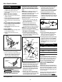
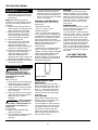
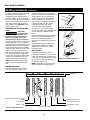
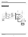
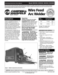
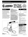
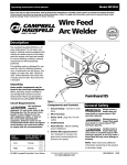
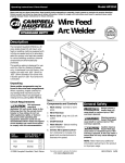
Model WG3013
Operating Instructions & Parts Manual
Please read and save these instructions. Read carefully before attempting to assemble, install, operate or maintain the product described.
Protect yourself and others by observing all safety information. Failure to comply with instructions could result in personal injury and/or
property damage! Retain instructions for future reference.
Description
4
This line of Campbell Hausfeld wire feed
welders is designed to be used on
standard 115V household current. The
welders are equipped with infinite wire
speed control to accurately select the
proper wire feed rate needed for various
welding conditions. Internal components
are thermostatically protected.
These welders are designed for use with
Flux Core Arc Welding (Gasless) or Gas
Metal Arc Welding (Mig) process. As
delivered from the factory, this welder
can weld with .024” (.6 mm) to .035”
(.9 mm) diameter wire. A starter spool
of .035” (.9 mm) flux-cored wire and a
.040 tip are included.
This equipment
requires a dedicated 115 volt circuit. Refer to the
following chart for the correct circuit
breaker or fuse rating. Do not run
other appliances, lights, or tools on
this circuit while operating this
equipment. Extension cords are not
recommended. Blown fuses and tripped
circuit breakers can result from failure
to comply with this recommendation.
CAUTION
Heat
Selector
Circuit Breaker or
Slow Blow Fuse
Low
15 amp
High
20 amp
© 2000 Campbell Hausfeld / Scott Fetzer
IT
3
Some welder components may be
found in the wire feed compartment.
!
1
5
FARMHAND 125
7
Circuit Requirements
1-800-746-5641
6
Unpacking
When unpacking, inspect carefully for
any damage that may have occurred
during transit. Report any damaged or
missing items by calling (800) 746-5641.
Need
Assistance?
Call Us First!
QUAL
BUILT TO LAST
SSURANCE PR
YA
RAM
OG
TM
Wire Feed
Arc Welder
2
Figure 1
Components and Controls
1. Ground Clamp - connect to work
piece.
2. Wire Feed Gun with .040 tip
3. Power Cord - plug into 115 volt
outlet.
4. On/Off Switch
5. Infinite Wire Speed Control turn clockwise to increase wire
speed and counterclockwise to
decrease wire speed.
General Safety
Danger means a
hazard that will
cause death or serious injury if the
warning is ignored.
!
DANGER
Warning means a
hazard that could
cause death or serious injury if the
warning is ignored.
! WARNING
6. Heat Selector - Selects welding
power. Four selections are possible
Caution means a
hazard that may
cause minor or moderate injury if the
warning is ignored. It also may mean a
hazard that will only cause damage to
property.
7. Polarity Hook-up - Attach torch
cable to (+) for MIG and (-) for flux
core wire.
NOTE: Note means any additional
information pertaining to the product
or its proper usage.
For parts, product & service information
visit www.chpower.com
!
CAUTION
IN970400AV 11/00
Wire Feed Arc Welder
General Safety
(Continued)
Torch is “live” (has
current potential)
at all times when machine is turned on.
! WARNING
! WARNING
Always keep a fire
extinguisher accessible while
performing arc welding
operations.
● Before starting or servicing any
electric arc welder, read and
understand all instructions. Failure
to follow safety precautions or
instructions can cause equipment
damage and/or serious personal
injury or death.
● All installation, maintenance, repair
and operation of this equipment
should be performed by qualified
persons only in accordance with
national, state, and local codes.
! WARNING
Improper use of electric arc
welders can cause electric
shock, injury, and death!
Take all precautions described in this
manual to reduce the possibility of
electric shock.
● Verify that all components of the
arc welder are clean and in good
condition prior to operating the
welder. Be sure that the insulation
on all cables, wire feed gun, and
power cords is not damaged.
Always repair or replace damaged
components before operating the
welder. Always keep welder panels,
shields, etc. in place when operating
the welder.
● Always wear dry, protective clothing
and welding gloves, and insulated
footwear.
● Always operate the welder in a
clean, dry, well ventilated area. Do
not operate the welder in humid,
wet, rainy, or poorly ventilated
areas.
● Be sure that the work piece is
properly supported and grounded
prior to beginning any electric arc
welding operation.
● Coiled welding cable should be
spread out before use to avoid
overheating and damage to
insulation.
Never immerse the
wire or wire feed
gun in water. If the welder becomes
!
DANGER
www.chpower.com
wet for any reason, be absolutely
certain that it is completely clean and
dry prior to attempting use!
● Always shut the equipment off and
unplug the power prior to moving
the unit.
● Always attach the work lead first.
● Verify that the work piece is
securely grounded.
● Always shut off electric arc welding
equipment when not in use, and cut
off any excess wire from the wire
feed gun.
● Never allow any part of the body to
touch the wire and ground or
grounded work piece at the same
time.
● Awkward welding conditions and
positions can be electrically
hazardous. When crouching,
kneeling or at elevations, be sure to
insulate all conductive parts, wear
appropriate protective clothing, and
take precautions to prevent injury
from falls.
● Never attempt to use this
equipment at current settings or
duty cycles higher than those
specified on the equipment labels.
● Never use an electric arc welder to
thaw frozen pipes.
! WARNING Flying
sparks and hot metal can
cause injury. As welds cool,
slag can be thrown off. Take
all precautions described in this manual
to reduce the possibility of injury from
flying sparks and hot metal.
● Wear ANSI approved face shield or
safety glasses with side shield
protection when chipping or
grinding metal parts.
● Wear ear plugs when welding
overhead to prevent spatter or slag
from falling into ears.
! WARNING Electric arc
Never look at arc
welding operations
without eye protection as described
above. Never use a shade filter lens
that is cracked, broken, or rated below
number 10. Warn others in the area not
to look at the arc.
! WARNING
! WARNING
Electric arc welding
operations cause sparks and
heat metal to temperatures
that can cause severe burns! Use
protective gloves and clothing when
performing any metal working
operation. Take all precautions
described in this manual to reduce the
possibility of skin and clothing burns.
● Make sure that all persons in the
welding area are protected from
heat, sparks, and ultraviolet rays.
Use additional face shields and
flame resistant barriers as needed.
● Never touch work pieces until
completely cooled.
! WARNING
Heat and sparks produced
during electric arc welding
and other metal working
operations can ignite flammable and
explosive materials! Take all
precautions described in this manual to
reduce the possibility of flames and
explosions.
● Remove all flammable materials
within 35 feet (10.7 m) of welding
arc. If removal is not possible,
tightly cover flammable materials
with fire proof covers.
● Do not operate any electric arc
welder in areas where flammable or
explosive vapors may be present.
● Take precautions to be sure that
flying sparks and heat do not cause
flames in hidden areas, cracks,
behind bulkheads, etc.
! WARNING
welding operations produce
intense light and heat and
ultraviolet (UV) rays. This
intense light and UV rays can cause
injury to eyes and skin. Take all
precautions described in this manual to
reduce the possibility of injury to eyes
and skin.
Fire hazard! Do not weld on
containers or pipes that
contain or have contained
flammable materials or gaseous or
liquid combustibles.
● All persons operating this
equipment or in the area while
equipment is in use must wear
protective welding gear including:
welding helmet or shield with at
least shade 10, flame resistant
clothing, leather welding gloves,
and full foot protection.
Arc welding closed cylinders
or containers such as tanks
or drums can cause explosion
if not properly vented! Verify that any
cylinder or container to be welded has
an adequate ventilation hole, so that
expanding gases can be released.
2
! WARNING
WG3013
General Safety
(Continued)
! WARNING
Do not breathe fumes that
are produced by the arc
welding operation. These
fumes are dangerous. If the welding
area cannot be adequately ventilated,
be sure to use an air supplied
respirator.
● Keep the head and face out of the
welding fumes.
● Do not perform electric arc welding
operations on metals that are
galvanized or cadmium plated, or
contain zinc, mercury, or beryllium
without completing the following
precautions:
a. Remove the coating from the
base metal.
b. Make sure that the welding area
is well ventilated.
c. Use an air-supplied respirator.
Extremely toxic fumes are created
when these metals are heated.
! WARNING
The electromagnetic field
that is generated during arc
welding may interfere with
the operation of various
electrical and electronic devices such as
cardiac pacemakers. Persons using such
devices should consult with their
physician prior to performing any
electric arc welding operations.
● Route the wire gun and work cables
together and secure with tape
when possible.
● Never wrap arc welder cables
around the body.
● Always position the wire gun and
work leads so that they are on the
same side of the body.
● Exposure to electromagnetic fields
during welding may have other
health effects which are not known.
Always be sure
that the welding
area is secure and free of hazards
(sparks, flames, glowing metal or slag)
prior to leaving. Be sure that
equipment is turned off and excess
wire is cut off. Be sure that cables are
loosely coiled and out of the way. Be
sure that all metal and slag has cooled.
! WARNING
!
DANGER
Cylinders can explode if
damaged. Shielding gas
cylinders contain gas under high
pressure. If damaged, a cylinder can
explode. Since gas cylinders are
normally part of the welding process,
be sure to treat them carefully.
● Protect compressed gas cylinders
from excessive heat, mechanical
shocks, and arcs.
● Install and secure cylinders in an
upright position by chaining them
to stationary support or equipment
cylinder rack to prevent falling or
tipping.
● Keep cylinders away from any
welding or other electrical circuits.
● Never allow a welding electrode to
touch any cylinder.
● Use only correct shielding gas
cylinders, regulators, hoses, and
fittings designed for the specific
application; maintain them and
associated parts in good condition.
● Turn face away from valve outlet
when opening cylinder valve.
● Keep protective cap in place over
valve except when cylinder is in use
or connected for use.
● Read and follow instructions on
compressed gas cylinders, associated
equipment, and CGA publication P-1
listed in Safety Standards.
Never use
flammable gasses
with MIG welders. Only inert or nonflammable gasses such as carbon
dioxide, argon, helium, or mixtures of
one or more of these gasses are
suitable for MIG welding.
!
DANGER
Never lift cylinders
off the ground by
their valves, caps, or with chains or slings.
! WARNING
ADDITIONAL SAFETY STANDARDS
ANSI Standard Z49.1 from American
Welding Society, 550 N.W. LeJune Rd.
Miami, FL 33126
Safety and Health Standards
OSHA 29 CFR 1910, from
Superintendent of Documents, U.S.
Government Printing Office,
Washington, D.C. 20402
National Electrical Code
NFPA Standard 70, from National Fire
Protection Association, Batterymarch
Park, Quincy, MA 02269
Safe Handling of Compressed Gases
in Cylinders
CGA Pamphlet P-1, from Compressed Gas
Association, 1235 Jefferson Davis
Highway, Suite 501, Arlington, VA 22202
Code for Safety in Welding and
Cutting
CSA Standard W117.2, from Canadian
Standards Association, Standards Sales,
178 Rexdale Boulevard, Rexdale,
Ontario, Canada M9W 1R3
Cutting And Welding Processes
NFPA Standard 51B, from National Fire
Protection Association, Batterymarch
Park, Quicy, MA 02269
Safe Practices For Occupational And
Educational Eye And Face
Protection
ANSI Standard Z87.1, from American
National Standards Institute, 1430
Broadway, New York, NY 10018
Refer to the Material Safety Data
Sheets and the manufacturers
instructions for metals, wire, coatings
and cleaners.
Installation
Selecting the proper location can
significantly increase performance,
reliability and life of the arc welder.
● For best results locate the welder in
an environment that is clean and
dry. Dust and dirt in the welder
retain moisture and increase wear
of moving parts.
● Place the welder in an area that
provides at least 12” (30,48 cm) of
ventilation space at both the front
and rear of the unit. Keep all
obstructions away from this
ventilation space.
● Store wire in a clean, dry location
with low humidity to preserve the
wire coating.
● The receptacle used for the welder
must be properly grounded and the
welder must be the only load on the
power supply circuit. Refer to the
Circuit Amps chart on page 1 for
correct circuit capacity.
● The use of an extension cord is not
recommended for electric arc
welding machines. The voltage drop
in the extension cord may significantly degrade the performance of
the welder.
Assembly
Welder components listed below
are in the wire feed compartment.
Open and remove.
HANDLE ASSEMBLY
1. Remove screws from handle. Slide
handle between welder front panel
www.chpower.com
3
Wire Feed Arc Welder
Assembly (Continued)
and top cover aligning the holes in
handle with holes in top cover.
2. Fasten screws through top cover and
into handle.
WHEEL AND AXLE ASSEMBLY
1. Insert axle supports into slots in the
welder housing.
2. Insert axle through the axle supports
and firmly push wheels onto axle.
3. Secure wheel with e-clips and wheel
caps.
GAS CYLINDER BRACKET ASSEMBLY
1. Place bracket on welder aligning the
holes in welder housing.
2. Fasten screws through bracket and
into cabinet.
FOOT ASSEMBLY
1. Place foot on welder and align holes
in the welder housing.
2. Fasten screws through foot into
cabinet.
welding wire even when the the gun
switch is not activated. Do not touch
these parts when the welding machine
is on.
NOTE: Before installing welding wire,
be sure that the diameter of the
welding wire matches the groove in the
drive roller on the wire feed
mechanism and the wire matches the
contact tip in the end of the gun. A
mismatch on any item could cause the
wire to slip or bind.
1. Verify the unit is off and open the
panel on the welder to expose the
wire feed mechanism.
2. Remove the spool quick lock, by
pushing in and rotating 1/4 turn
counterclockwise. The knob, spring,
and spool spacer can now be removed.
NOTE: Spool spacer and spindle spacer
act as an 8” spool spindle adapter.
Purchase of an adapter is not necessary.
* See Figure 4 for assembly.
3. Loosen the wire feed tensioning
screw on the drive mechanism. This
allows initial feeding of the wire into
the gun liner by hand.
Tension
Screw
Panel
Guide
Tube
Drive Roller
6. Feed the wire through the wire feed
guide tube, over the groove in the
drive roll and into the gun liner.
Tighten the wire feed tensioning screw
so that it is snug. Do not over tighten.
7. Remove the nozzle by turning
counterclockwise. Then unscrew
the contact tip from the end of the
welding torch (See Figure 5). Plug the
welder into the proper power supply
receptacle.
Torch Neck
Contact Tip
Nozzle
Figure 5 - Torch Nozzle
HINT: Keep torch cable straight when
feeding wire.
8. Turn on the welder and set the wire
speed rate to 5. Activate the gun
switch until the wire feeds out past
the torch end. Turn welder off.
9. Carefully slip the contact tip over the
wire and screw it into the torch neck.
Install the nozzle by turning clockwise (See Figure 6). Cut the wire off
approximately 1/4” from the end of
the nozzle.
Contact Tip Markings
Wire Size
mm
Spindle
Spacer
Spool
Spacer
Figure 2 - WG3013 Assembly
Ground Clamp
1. Loosen hex nut on work clamp.
2. Insert cord through clamp handle and
slide bare wire under the clamp block.
Tighten hex nut making sure bare
wire is clamped securely (Figure 3).
Spool
Lock
Figure 3 - Work Clamp Assembly
Wire Installation
Welding power
may be applied to
the output terminals, feed roll, work
clamp, gun cable connection and
! WARNING
or
.6
.030”
or
.8
.035”
or
.9
.040”
or
1.0
Spindle
4” or 8”
Spool
Clamping
Block
.024”
*Reverse
position and
insert into 8”
spool
Spring
Figure 4 - Weld Wire Routing
4. Install the wire spool onto the
spindle so that the wire can come off
the spool on the end closest to the
wire feed guide tube. Do not cut
the wire loose yet. Install the spool
spacer, spring, and quick lock knob
by pushing in and turning the knob
1/4 rotation clockwise.
5. Hold the wire and cut the wire end
from the spool. Do not allow the wire
to unravel. Be sure that the end of the
wire is straight and free of burrs.
www.chpower.com
4
POLARITY
For gas shielded welding, connect the
cable coming out of the torch to the (+)
socket and the ground clamp cable to
the (-) socket on the front panel. For
flux-core (no-gas) welding, connect
torch to (-) and work clamp to (+).
DUTY CYCLE / THERMOSTATIC
PROTECTION
Welder duty cycle is the percentage of
actual weld time that can occur in a ten
minute interval. For example, at a 10%
duty cycle, actual welding can occur for
one minute, then the welder must cool
for nine minutes.
Internal components of this welder are
protected from overheating with an
automatic thermal switch. A yellow
lamp is illuminated on the front panel
WG3013
Assembly (Continued)
if the duty cycle is exceeded. Welding
operations may continue when the
yellow lamp is no longer illuminated.
Handshield
Assembly
NOTE: Shielding gas is not required if
flux-cored welding wire is used.
1. Cut retainer stiffeners and
detachable handle away from shield.
Trim the excess plastic to remove
sharp edges.
2. Insert filter lens.
3. Attach the stiffeners over the pins on
the lens retainers (See Figure 6).
Lens
Lens
Retainer
Retainer
Stiffener
Figure 6
4. To attach the handle, place shield on
a flat surface and press handle into
place (See Figure 7).
Figure 7
NOTE: If you have never welded
before or have little experience, a
full face helmet is recommended.
Both hands are needed to stabilize
and control the angle and arc
length of the torch.
Shielding Gas
Installation
Improper handling
and maintenance
of compressed gas cylinders and
regulators can result in serious injury
!
DANGER
or death! Always secure gas cylinders
to the tank bracket kit, a wall or other
fixed support to prevent the cylinder
from falling over. Read, understand,
and follow all the compressed gases
and equipment hazards in the safety
instructions.
GAS TYPES
There are 3 types of gas generally used
for gas metal arc welding; 100% argon,
a mixture of 75% argon and 25%
carbon dioxide (C25) or 100% carbon
dioxide. However, 100% carbon
dioxide is not recommended due to
unsatisfactory weld beads. This welder
does not perform well with 100%
carbon dioxide. The 75/25 mixture is
recommended for general steel
welding. For aluminum welding, use
100% argon. Cylinders of either type
gas may be obtained at your local
welding supply outlet. Secure cylinder
in place on your welding machine or
other support to prevent the cylinder
from falling over.
NOTE: Use of incorrect gas may lead to
little or no penetration of welding
bead.
REGULATOR (NOT INCLUDED)
The regulator provides a constant
shielding gas pressure and flow rate
during the welding process.
HOOKUP PROCEDURE
Cylinder gas is
under high
pressure. Point cylinder outlet away
from yourself and any bystanders
before opening.
! WARNING
1. These units fit a 20 cubic ft bottle.
2. With the cylinder securely installed,
remove the cylinder cap, stand to the
side of the cylinder opposite the
outlet, and open the valve slightly,
turning counterclockwise. When gas
is emitted from the cylinder, close the
valve by turning clockwise. This will
blow out dust or dirt that may have
accumulated around the valve seat.
3. Install the regulator onto the
cylinder valve, keeping the face of
the gauges in the vertical position
and tighten the stem nut securely
to the gas valve.
4. Install one end of the gas hose (not
included) to the fitting on the rear
of the welder and the other end to
the fitting on the regulator using
hose clamps (not included) on each
connection. Make sure the gas hose
is not kinked or twisted.
5. Once again, stand opposite the
cylinder outlet and slowly open the
cylinder valve. Inspect for leaks in
the connections.
6. Pull the trigger on the gun to allow
the gas to flow. While the trigger is
pulled and gas is flowing, adjust the
gas regulator to 30-35 cfh (cubic
feet per hour). Release the trigger.
7. Remember to close the gas valve
when finished welding.
Operation
1. Be sure to read,
understand, and comply
with all precautions in
the General Safety
Information section. Be
sure to read the entire section
entitled Welding Guidelines prior to
using this equipment.
2. Verify welder is off.
3. Verify that the surfaces of metals to
be joined are free from dirt, rust,
paint, oil, scale or other contaminants. These contaminants make
welding difficult and cause poor
welds.
MANUAL
!
DANGER
All persons operating this
equipment or in the area
while equipment is in use
must wear protective welding gear
including: eye protection with proper
shade, flame resistant clothing, leather
welding gloves, and full foot
protection.
WHETHER OR
! CAUTION NOT THE TRIGGER
IS PULLED, the welding wire is LIVE
whenever the welder is turned ON.
! WARNING
If heating, welding, or
cutting materials that are
galvanized, zinc plated, lead,
or cadmium plated refer to the General
Safety Information Section for
instructions. Extremely toxic fumes are
created when these metals are heated.
4. Connect the work clamp to the
work piece or workbench (if metal).
Make sure the contact is secure.
Avoid surfaces with paint, varnish,
corrosion, or non-metallic materials.
5. Position the Heat Selector on the
front panel to the desired setting.
www.chpower.com
5
Wire Feed Arc Welder
Operation (Continued)
See application decal inside door of
wire feed compartment for proper
heat settings.
NOTE: These settings are general
guidelines only. Heat setting may vary
according to welding conditions and
materials.
6. Rotate the Wire Speed Control to
setting number 5 to start with, then
adjust as needed after test weld.
7. Plug the input cord into a proper
voltage receptacle with proper
circuit capacity (See Chart under
circuit requirements on page 1).
8. Switch the welder ON.
9. Verify that the wire is extended
1/4” from the contact tip. If not,
squeeze the trigger to feed
additional wire, release the trigger,
and cut wire to proper length.
10. Position the wire feed gun near the
work piece, lower the welding
helmet by nodding the head, or
position the hand shield, and
squeeze the gun trigger. Adjust heat
setting and wire speed as needed.
11. When finished welding, turn welder
off and store properly.
3. Clean the wire groove on the drive
roll. Remove wire from the feed
mechanism, remove screws from the
drive roll housing. Use a small wire
brush to clean the drive roll. Replace
if worn or damaged.
Consumer and Wear Parts
The following parts require routine
maintenance:
• Wire feed drive roller
• Gun liner - replace if worn
• Nozzle/contact tips
• Wire - this welder will accept either
4” or 8” diameter spools. Welding wire
is susceptible to moisture and oxidizes
over time, so it is important to select a
spool size that will be used within
approximately 6 months. For mild steel
welding, AWS ER70S6 solid wire or
AWS E71T-GS flux-core wire is
recommended.
• Contact tips - use Campbell Hausfeld,
Tweco®, and other compatible tips.
• Nozzle - use Tweco® style or compatible
nozzle. Use Campbell Hausfeld nozzle
model WT5021 found at place of
purchase of welder, or use Tweco® style
nozzle (or compatible nozzle) found at
local welding supply store.
Maintenance
Disconnect power
supply and turn
machine off before inspecting or
servicing any components. Keep the
wire compartment cover closed at all
times unless the wire needs
replacement.
! WARNING
Before every use:
1. Check condition of weld cables and
immediately repair or replace any
cables with damaged insulation.
2. Check condition of power cord and
immediately repair or replace any
cord if damaged.
3. Inspect the condition of the gun tip
and nozzle. Remove any weld slag.
Replace gun tip or nozzle if
damaged.
Do not operate this
! WARNING welding machine
with cracked or missing insulation on
welding cables, wire feed gun, or
power cord.
Every 3 months:
1. Replace any unreadable safety
labels on the welder.
2. Use compressed air to blow all dust
and lint from the ventilation
openings.
MIG
WT5021
Figure 8 - Nozzle
Changing Wire Sizes
DRIVE ROLLER
There are two grooves in the Drive
Roller. The small groove is for .024” (.6
mm) wire and the other is for .030” .035” (.8 - .9 mm) wire. Remove the
roller cover and flip the drive roll to
choose the correct groove (see Parts
Breakdown).
FLUX CORE WIRE
Due to small inconsistencies in wire
diameter, using one size larger tip is
recommended. For example:
• If wire diameter is .030, use .035 tip.
• If wire diameter is .035, use .040 tip.
This welder is setup for .035 (.9 mm)
wire and has a .040 tip. Since this
welder uses .030 and .035 Flux Core
Wire, the drive roller should be in its
factory pre-set condition.
www.chpower.com
6
MIG WIRE
Since MIG wire maintains fair wire
diameter consistency, the contact tip
used should match the wire size used.
When using .024 (.6 mm) wire, use the
small groove on the drive roller. When
using .030 - .035 (.8 - .9 mm) MIG or
Aluminum wire, use the factory set
large groove.
ALUMINUM WIRE
When using Aluminum wire, it is best
to use a larger size tip than the wire
size being used. For example:
• If wire diameter is .030, use .035 tip.
When using .030 - .035 (.8 - .9 mm) MIG
or Aluminum wire, use the factory set
large groove. Aluminum wire is very
weak and should not have the same
tension on the drive roller as Flux Core
or MIG wire should. When tensioning
Aluminum wire down to the Drive
Roller, turn the tension screw three full
turns or until the Drive Roller begins to
grip the wire and feed it through the
torch cable.
Call (800) 746-5641
for replacement parts.
WG3013
Welding Guidelines
General
Nozzle
Contact
Tip
Shielding
Gas
Flux
(Gasless
only)
Slag
Weld
Wire
Crater
Work Piece
Figure 9 - Weld Components
This line of welding machines can
utilize the Flux Cored Arc Welding
(Gasless) process or the Gas Metal Arc
Welding (MIG) process. The weld must
be protected (shielded) from
contaminates in the air while it is
molten. The gasless process uses a
tubular wire with a flux material inside.
The flux creates a shielding gas when
melted. The MIG process uses inert gas
to shield the weld while molten.
When current is produced by a
transformer (welding machine) and
flows through the circuit to the weld
wire, an arc is formed between the end
of the weld wire and the work piece.
This arc melts the wire and the work
piece. The melted metal of the weld
wire flows into the molten crater and
forms a bond with the work piece as
shown (Figure 9).
Arc Welding Basics
Five basic techniques affect weld
quality. These are: wire selection, heat
setting, weld angle, wire speed, and
travel speed. An understanding of
these techniques is necessary for
effective welds.
HEAT SETTING
The correct heat involves the adjustment of the welding machine to the
required setting. Heat or voltage is
regulated by a switch on the welder.
The heat setting used depends on the
size (diameter) and type of wire,
position of the weld, and the thickness
of the work piece. Consult specif-
ications listed on the welder. It is
suggested that the welder practice with
scrap metal to adjust settings and
compare welds with Figure 11.
WIRE TYPE AND SIZE
The correct choice of wire type involves
a variety of factors, such as welding
position, work piece material type,
thickness and condition of surface to be
welded. The American Welding Society,
AWS, has set up certain requirements
for each type of wire.
FLUX-CORE WIRE
E - 7 0 T - GS
Weld strength, times
10,000 psi
Welding positions (0
for flat or horizontal,
1 for any position)
Tubular flux core wire
Flux type
AWS E71T-GS or E71T-11 is
recommended for this welder.
SOLID WIRE
ER - 70 S - 6
Weld strength, times
1,000 psi
Solid wire
Wire composition
ER-70S6 is recommended for this
welder.
WELD ANGLE
Weld angle is the angle at which the
nozzle is held during the welding
process. Using the correct angle
ensures proper penetration and bead
formation. As different welding
positions and weld joints become
necessary, nozzle angle becomes an
increasingly important factor in
obtaining a satisfactory weld. Weld
angle involves two positions - travel
angle and work angle.
Travel angle is the angle in the line of
welding and may vary from 5º to 45º
from the vertical, depending on
welding conditions.
Work angle is the angle from hori-
zontal, measured at right angles to the
line of welding. For most applications, a
45º travel angle and 45º work angle is
sufficient. For specific applications,
consult an arc welding handbook.
5º - 45º
WORK ANGLE
5º - 45º
TRAVEL ANGLE
Figure 10 - Weld Angle
WIRE SPEED
The wire speed is controlled by the
knob on the front panel. The speed
needs to be “tuned” to the rate at
which the wire is being melted in the
arc. Tuning is one of the most critical
functions in wire feed welding. Tuning
should be performed on a scrap piece
of metal the same type and thickness as
that to be welded. Begin welding with
one hand “dragging” the gun nozzle
across the scrap piece while adjusting
the wire speed with the other hand.
Too slow of speed will cause sputtering
and the wire will burn up into the
contact tip. Too fast a speed will also
cause a sputtering sound and the wire
will push into the plate before melting.
A smooth buzzing sound indicates the
wire speed is properly tuned. For
aluminum, wire speed is typically set
higher (7 - 9 speed range).
NOTE: Repeat the tuning procedure
each time there is a change in heat
setting, wire diameter or type, or work
piece material type or thickness.
TRAVEL SPEED
The travel speed is the rate at which
the torch is moved across the weld
area. Factors such as diameter and type
of weld wire, amperage, position, and
www.chpower.com
7
Wire Feed Arc Welder
Welding Guidelines (Continued)
work piece material thickness all affect
the speed of travel necessary for
completing a good weld (See Fig. 11).
When the speed is too fast, the bead is
narrow and bead ripples are pointed as
shown. When the speed is too slow, the
weld metal piles up and the bead is
high and wide. For aluminum, travel
speed is typically faster.
SLAG REMOVAL (FLUX-CORE WIRE
ONLY)
Wear ANSI
approved safety
glasses (ANSI Standard Z87.1) and
protective clothing when removing
slag. Hot, flying debris can cause
personal injury to anyone in the area.
! WARNING
After completing the weld, wait for the
welded sections to cool. A protective
coating called slag now covers the weld
bead which prevents contaminants in
the air from reacting with the molten
metal. Once the weld cools to the point
that it is no longer glowing red, the
slag can be removed. Removal is done
with a chipping hammer. Lightly tap
the slag with the hammer and break it
loose from the weld bead. The final
clean-up is done with a wire brush.
NOTE: When making multiple weld
passes, remove the slag before each
pass.
overhead. Welding in the flat position
is easier than any of the others because
welding speed can be increased, the
molten metal has less tendency to run,
better penetration can be achieved,
and the work is less fatiguing. Welding
is performed with the wire at a 45º
travel angle and 45º work angle.
Other positions require different
techniques such as a weaving pass,
circular pass, and jogging. A higher skill
level is required to complete these
welds.
Overhead welding is the least desirable
position as it is the most difficult and
dangerous. Heat setting and wire
selection will vary depending upon the
position.
All work should be performed in the
flat position if possible. For specific
applications, consult an arc welding
technical manual.
WELD PASSES
Sometimes more then one pass is
necessary to fill the joint. The root pass
is first, followed by filler passes and the
cover pass. If the pieces are thick, it may
be necessary to bevel the edges that
are joined at a 60º angle.
Cover
Filler
Root
Figure 12 - Weld Passes
Figure 13 - Multiple Weld Passes
NOTE: Remember to remove the slag
before each pass for gasless process.
WELDING POSITIONS
Four basic welding positions can be
used; flat, horizontal, vertical, and
Base Metal
Normal Heat, Wire Speed, Travel
Speed
Travel Speed Too Fast
Heat Too Low
Travel Speed Too Slow
Heat Too High
Figure 11 - Weld Appearance
Wire Speed Too Slow
Wire Speed Too Fast
www.chpower.com
8
WG3013
Welding Guidelines (Continued)
PUSH VS PULL TECHNIQUE
The type and thickness of the work
piece dictates which way to point the
gun nozzle. For thin materials (18 gauge
and up) and all aluminum, the nozzle
should point out in front of the weld
puddle and push the puddle across the
workpiece. For thicker steel, the nozzle
should point into the puddle to increase
weld penetration. This is called
backhand or pull technique
(See Figure 14).
ALUMINUM WELDING
Any aluminum surface to be welded,
must be cleaned thoroughly with a
stainless steel brush to eliminate any
oxides on the weld and grounding
surface. 100% Argon must be used
when welding aluminum. If Argon is not
used, metal penetration is unlikely.
Supply Cable
Replacement
1. Verify that welder is OFF and power
cord disconnected.
2. Remove welder cover to expose the
ON/OFF switch.
3. Disconnect the black and white
power cord wires connected to the
ON/OFF switch.
4. Disconnect the green power cord
wire connected to welder frame.
5. Loosen the cord strain screw(s) and
pull cord out of strain relief.
6. Install new cord in reverse order.
PULL
Figure 14
PUSH
www.chpower.com
9
Wire Feed Arc Welder
For Information About This Product, Call 1-800-746-5641
Troubleshooting Chart - Welder
Symptom
Possible Cause(s)
Corrective Action
No output
1. Duty cycle exceeded
2. Poor ground clamp connection
3. Defective power switch
4. Blown breaker or fuse
1. Allow welder to cool until ON/OFF Switch lamp goes out
2. Be sure all connections are secure, and attaching surface is
clean
3. Replace switch
4. Reduce circuit load, reset breaker or replace fuse
1. Wrong size gun tip
2. Gun liner clogged or
damaged
3. Gun tip clogged or damaged
4. Feed roller worn
5. Not enough tension
1. Use proper size gun tip
2. Clean or replace gun liner
Gun nozzle arcs to work
surface
Slag inside gun nozzle
Clean slag from gun nozzle
Ground clamp and/or
cable gets hot
1. Poor contact
1. Be sure all connections are secure, and attaching surface is
clean
2. Never use an extension cord longer than 20 ft
Wire tangles at drive roller
3. Clean or replace gun tip
4. Replace
5. Tighten tensioning screw
2. Using an extension cord with
excessive length
Wire does not feed
1. Wire jammed
2. Out of wire
3. Not enough tension
4. Wire liner worn
5. Wire disconnected internally
6. Contact tip clogged
1. Reload wire
2. Replace wire spool
3. Tighten tensioning screws if wire is slipping
4. Replace liner
5. Call 1-800-746-5641 for assistance
6. Replace contact tip
(Aluminum) Wire burns back
into tip or (Aluminum) Metal
bubbles or burns through
1. Wire speed too slow
2. Travel speed too slow or heat
is too high
1. Run speed in 7 - 10 range
2. Increase the travel speed or reduce heat settings
Troubleshooting Chart - Welds
Symptom
Possible Cause(s)
Corrective Action
Bead is intermittently too
thin
1. Fast and/or inconsistent travel speed
2. Output heat setting too low
1. Decrease and maintain constant travel speed
2. Increase output heat setting
Bead is intermittently too
thick
1. Slow and/or inconsistent travel speed
2. Output heat setting too high
1. Increase and maintain travel speed
2. Reduce output heat setting
Ragged depressions at
edge of weld
1. Travel speed too fast
2. Wire speed too fast
3. Output heat setting too high
1. Decrease travel speed
2. Decrease wire speed
3. Reduce output heat setting
Weld bead does not
penetrate base metal
1. Inconsistent travel speed
2. Output heat setting too low
3. No or low shielding gas
4. Wrong shielding gas (aluminum)
5. Extension cord is too long
6. (Aluminum) Possible oxide buid-up on
surface
1. Decrease and maintain constant travel speed
2. Increase output heat setting
3. Use gas for MIG process or refill bottle
4. Use only 100% Argon gas
5. Never use an extension cord longer than 20 ft
6. Clean surface thoroughly with a stainless steel
brush only
Wire sputters and sticks
1. Damp wire
2. Wire speed too fast
3. Wrong type of wire
4. No or low shielding gas
1. Use dry wire and store in dry location
2. Reduce wire speed
3. Use flux core wire when not using gas
4. Use gas for MIG process or refill bottle
www.chpower.com
10
WG3013
Limited 5-3-1 Warranty
1.
Duration: The manufacturer warrants that it will repair, at no charge for parts or labor, the Welder, Welding Gun, or Cables, proven defective in material or
workmanship, during the following time period(s) after date of original retail purchase:
For 5 Years: The Welder Transformer and Rectifier
For 3 Years: The Entire Welder (excluding clamps, welding gun, electrode holder, cables, or accessories packed with welder)
For 1 Year: The Welding Clamps, MIG Gun, Electrode Holder, Accessories, and Welding Cables (as applicable)
2.
Who Gives This Warranty (Warrantor):
The Campbell Group / A Scott Fetzer Company
100 Production Drive
Harrison, OH 45030
Telephone: (513)-367-4811
3.
4.
Who Receives This Warranty (Purchaser): The original purchaser of the Campbell Hausfeld product.
What is covered under this warranty: Defects in material and workmanship which occur within the duration of the warranty period. This warranty
extends to the Welder, the Welders Transformer and Rectifier, Welding Gun or Electrode Holder, and cables only.
5.
What is not covered under this warranty:
A.
Implied warranties, including those of merchantability and FITNESS FOR A PARTICULAR PURPOSE ARE LIMITED IN DURATION TO THIS EXPRESS
WARRANTY. After this period, all risks of loss, from whatever reason, shall be on the purchaser. Some states do not allow limitations on how long an
implied warranty lasts, so above limitations may not apply to you.
B.
ANY INCIDENTAL, INDIRECT, OR CONSEQUENTIAL LOSS, DAMAGE, OR EXPENSE THAT MAY RESULT FROM ANY DEFECT FAILURE OR MALFUNCTION OF
THE CAMPBELL HAUSFELD PRODUCT. Some states do not allow limitations on how long an implied warranty lasts, so above limitations may not apply
to you.
C.
This warranty does not apply to any accessory items included with the product which are subject to wear from usage; the repair or replacement of
these items shall be at the expense of the owner. These MIG items include but are not limited to; Contact Tips, Nozzles, Gun Liners, Drive Rollers, Felt
Wire Cleaner. In addition, this warranty does not extend to any damage caused by the untimely replacement or maintenance of any of the previously
listed CONSUMABLE parts.
D.
Any failure that results from accident, purchaser’s abuse, neglect or failure to operate products in accordance with instructions provided in the owner’s
manual(s) supplied with the product.
E.
7.
Pre-delivery service, i.e. assembly and adjustment.
Responsibilities of Warrantor under this warranty: Repair or replace, at Warrantor’s option, products or components which have failed within duration
of the warranty period.
8.
Responsibilities of purchaser under this warranty:
A. Deliver or ship the Campbell Hausfeld product or component to Campbell Hausfeld. Freight costs, if any, must be borne by the purchaser.
B. Use reasonable care in the operation and maintenance of the products as described in the owner’s manual(s).
9.
When Warrantor will perform repair or replacement under this warranty: Repair or replacement will be scheduled and serviced according to the
normal work flow at the servicing location, and depending on the availability of replacement parts.
This Limited Warranty gives you specific legal rights and you may also have other rights which vary from state to state.
www.chpower.com
11
Wire Feed Arc Welder
WG3013 Wiring Diagram
+
ON/OFF
S1
S3
T1
T2
S5
1
2
1
-
~
2
M
~
FAN
S2
MIN
4
5
MAX
-
+
S5 NC
OPENS @ 127˚C
Y
GREEN
BLACK
WHITE
6
GROUND
DRIVE
DECK
~
-
S4
GUN
L2 L1
4
3
2
M
1
WIRE SPEED
CONTROL BOARD
www.chpower.com
12
+
WG3013
For Replacement Parts, call 1-800-746-5641
24
44
3
45
33
28
23
25
43
29
26
2
6
5
Please provide following information:
- Model number
- Serial number
- Part description and number as
shown in parts list
27
Address parts correspondence to:
The Campbell Group
Attn: Parts Department
100 Production Drive
Harrison, Ohio 45030 U.S.A.
27
4
** Contact Tip (See chart on Page 15)
16
17
1
22
18
19
20
21
39
40
12
34
40
46
14
13
41
31
37
11
35
8
7
9 & 10
36
30
38
42
3
15
32
1
40
MODEL WG3013
www.chpower.com
13
Wire Feed Arc Welder
Replacement Parts List - Models WG3013
Ref
No.
1
2
3
4
5
Part Number for Model:
WG3013
Description
Qty
Torch assembly and hose (Includes Nos. 2-6, 34, and 50-52)
Torch body, front and back
Hanger clip
Nozzle, Tweco® Style
Trigger knob
WC600700AV
WC600201AV
WC600003AV
WT502100AJ
WC600202AV
1
1
1
1
1
6
7
8
9
10
Torch contact spring
Work clamp (Cord not included)
Welding cable 8 AWG (6 ft)
Wire speed knob
Wire speed control board
WC600203AV
WC100100AV
❋
WC400201AV
WC402100AV
1
1
1
1
1
11
12
13
14
15
Heat selector switch
On/off switch
Safety decal
Handle
Power cord 14-3 AWG (6 ft) Type SJT
WC400300AV
WC400000AV
DK670100AV
WC300600AV
❋
2
1
1
1
1
16
17
18
19
20
Spool spindle
#10-32 x .5” Pan head sheet metal screw
Wire
Spool adapter
Spool spring
WC500300AV
❋
See Chart Below
WC500200AV
WC500101AV
1
2
1
1
1
WC500100AV
WC500000AV
WC500003AV
WC500002AV
WC500001AV
WC500004AV
❋
WC500005AV
WC500007AV
WC102000AV
WC701200AV
WC702100AV
WC600208AV
WC702200AV
WC703100AV
WC703500AV
WC000200AV
WC000300AV
WC600009AV
❋
WC703600AV
❋
WC600701AV
WC600305AV
WC600204AV
WC802000AV
1
1
1
1
1
1
3
1
1
1
2
1
1
1
1
1
2
2
1
9
2
2
1
1
1
1
21
Spool locking hub
22
Drive deck assembly (Includes Nos. 23-29)
23
Tension spring
24
Tension screw
25
Roller .6-.9mm (.024-.035 in.)
26
Roller cover
27
#8-36 x 1.5” Pan head screw
28
Swing arm
29
Swing arm roller
30
Strain relief
31
Wheel
32
Front foot
33
Liner, coated metal
34
Gas cylinder bracket
35
Axle
36
Wheel hub
37
Dinse connector
38
Dinse socket
39
Torch ring
40
#10-24 x 1/2” Screw
41
Axle support
42
5mm I.D. e-ring
43
Swan neck with Diffuser
44
Trumpet liner
45
Valve body
46
Gas bottle strap
❋ Standard hardware item, available at local hardware or welder supply store
OPTIONAL WIRE
Type
Description
Part Number
(1 pound)
Flux
Flux
MIG
MIG
MIG
Aluminum MIG
E71T-GS
E71T-GS
ER70S6
ER70S6
ER70S6
ER5356
WE200001AV
WE200501AV
WE300001AV
WE300501AV
WE301001AV
WE303001AV
.030”
.035”
.024”
.030”
.035”
.030”
Part Number
(10 pound)
WE201000AV
WE201500AV
WE301500AV
WE302000AV
WE302500AV
N/A
www.chpower.com
14
**OPTIONAL CONTACT TIPS (4/package)
Size
mm
in.
Part Number
0.6
0.8
0.9
0.024
0.030
0.035
WT501200AJ
WT501300AJ
WT501400AJ
WG3013
Glossary of Welding Terms
AC or Alternating Current - electric
current that reverses direction
periodically. Sixty cycle current travels
in both directions sixty times per
second.
Arc Length - the distance from the
end of the electrode to the point
where the arc makes contact with the
work surface.
Base Metal - the material to be
welded.
Butt Joint - a joint between two
members aligned approximately in the
same plane.
Crater - a pool, or pocket, that is
formed as the arc comes in contact with
the base metal.
DC or Direct Current - electric current
which flows only in one direction. The
polarity (+ or -) determines which
direction the current is flowing.
DC Reverse Polarity - occurs when
the electrode holder is connected to
the positive pole of the welding
machine. Reverse Polarity directs more
heat into melting the electrode rather
then the work piece. It is used on
thinner material.
DC Straight Polarity - occurs when
the electrode holder is connected to
the negative pole of the welding
machine. With straight polarity more
heat is directed to the work piece for
better penetration on thicker material.
Electrode - a coated metal wire having
approximately the same composition as
the material being welded.
Fillet Weld - approximately a triangle
in cross-section, joining two surfaces at
right angles to each other in a lap, T or
corner joint.
Flux - a coating, when heated, that
produces a shielding gas around the
welding area. This gas protects the
parent and filler metals from impurities
in the air.
Flux Cored Arc Welding (FCAW) also called Gasless, is a welding process
used with a wire-feed welding
machine. The weld wire is tubular with
flux material contained inside for
shielding.
Gas Metal Arc Welding (GMAW) also called MIG, is a welding process
used with a wire feed welding
machine. The wire is solid and an inert
gas is used for shielding.
Gas Tungsten Arc Welding (GTAW) also called TIG, is a welding process
used with welding equipment with a
high frequency generator. The arc is
created between a non-consumable
tungsten electrode and the work piece.
Filler metal may or may not be used.
Lap Joint - a joint between two
overlapping members in parallel
planes.
Open Circuit Voltage (OCV) - the
voltage between the electrode and the
work clamp of the welding machine
when no current is flowing (not
welding). The OCV determines how
quickly the arc is struck.
Overlap - occurs when the amperage is
set too low. In this instance, the molten
metal falls from the electrode without
actually fusing into the base metal.
Porosity - gas pockets, or cavities,
formed during weld solidification. They
weaken the weld.
Penetration - the depth into the work
piece that has been heat effected by
the arc during the welding process. A
good weld achieves 100% penetration
meaning that the entire thickness of
the work piece has been heated and
resolidified. The heat effected area
should be easily seen on the opposite
side of the weld.
Slag - a layer of flux soot that protects
the weld from oxides and other
contaminants while the weld is
solidifying (cooling). Slag should be
removed after weld has cooled.
Spatter - metal particles thrown from
the weld which cool and harden on the
work surface. Spatter can be minimized
by using a spatter resistant spray on the
work piece before welding.
Tack Weld - weld made to hold parts
in proper alignment until final welds
are made.
Travel Angle - the angle of the
electrode in the line of welding. It
varies from 5º to 45º depending on
welding conditions.
T Joint - made by placing the edge of
one piece of metal on the surface of
the other piece at approximately a 90º
angle.
Undercut - a condition that results
when welding amperage is too high.
The excessive amperage leaves a
groove in the base metal along both
sides of the bead which reduces the
strength of the weld.
Weld Pool or Puddle - a volume of
molten metal in a weld prior to its
solidification as weld metal.
Weld Bead - a narrow layer or layers of
metal deposited on the base metal as
the electrode melts. Weld bead width is
typically twice the diameter of the
electrode.
Work Angle - the angle of the
electrode from horizontal, measured at
right angles to the line of welding.
Shielded Metal Arc Welding
(SMAW) - also called Stick, is a welding
process with uses a consumable
electrode to support the arc. Shielding
is achieved by the melting of the flux
coating on the electrode.
www.chpower.com
15
Wire Feed Arc Welder
Notes
www.chpower.com
16