1
USER MANUAL
Whisper Power Center
Quick Settings Guide
Art.nr. 40200886
WHISPER POWER BV
Kelvinlaan 82
9207 JB Drachten
Netherlands
Tel.: +31-512-571550
Fax.: +31-512-571599
www.whisperpower.eu
V1 October 2011
TABLE OF CONTENTS
1
2
3
4
5
6
7
8
9
2
TABLE OF CONTENTS
INTRODUCTION ...................................................................................................................................... 3
WPC – PSCP: QUICK START GUIDE........................................................................................................ 4
2.1
Setting of the language ..................................................................................................................... 4
2.2
Adaptation to the source .................................................................................................................. 4
2.3
Adaptation to the battery ................................................................................................................. 5
BASIC DISPLAYS ..................................................................................................................................... 6
ACTIVATING AND DEACTIVATING THE WPC ....................................................................................... 7
SETTING OF THE RCC REMOTE CONTROL ............................................................................................. 8
5.1
Setting of the language {5000} ......................................................................................................... 8
5.2
Other languages {5036} ...................................................................................................................... 8
5.3
Setting of time {5001} and date {5002} ............................................................................................ 8
5.4
User level {5012} .................................................................................................................................... 9
5.5
Drive the remote control to the user level basic {5019} ............................................................... 9
BATTERY SETTINGS ................................................................................................................................ 10
6.1
Default battery settings .................................................................................................................... 10
6.2
Battery Temperature Sensor (BTS) ................................................................................................... 11
6.3
Battery Status Indicator (BSI) ............................................................................................................ 11
AC SETTINGS ........................................................................................................................................ 12
7.1
Smart boost functionality.................................................................................................................. 12
7.2
AC input ............................................................................................................................................... 13
7.2.1 User setting: Quick setting of the max current of the ac source ......................................... 13
7.2.2 Setting of the max current of the ac generator ..................................................................... 13
7.2.3 Allow to overrun the maximum input current of the AC source .......................................... 14
7.2.4 Automatic selection of AC source ............................................................................................ 14
7.3
AC output ............................................................................................................................................ 16
7.4
AC generator behavior .................................................................................................................... 17
7.5
User settings: Controlling the variable speed genset power demand ................................... 18
USER SETTING: AUTO START SETTINGS ................................................................................................. 20
8.1
Enable auto start on the DDC ......................................................................................................... 20
8.2
Auto start on battery voltage .......................................................................................................... 21
8.3
Auto start on battery SOC (only with BSI) ...................................................................................... 22
8.4
Auto start on AC output power ...................................................................................................... 22
8.5
Enable a silent period ....................................................................................................................... 23
8.6
User preference: Dipswitch functions ............................................................................................ 24
8.6.1 Prohibit automatic start when grid is available ....................................................................... 24
8.6.2 Preferred input ............................................................................................................................... 25
NOTES ................................................................................................................................................... 26
July 2012 / WPC / EN
INTRODUCTION
1 INTRODUCTION
The GV-7i is an integrated inverter-charger-variable speed generator solution which has standard
factory setting to operate with a AGM battery set of 12V/[tbd]Ah, 24V/[tbd]Ah or 48V/[tbd]Ah. If
the auto start/stop cable is connected from the connection board of the WPC to the DDC remote
panel input, the auto-start/stop functionality can be enabled on the display.
Settings have been chosen to start the generator if the service set has a low voltage, or if the
power consumption is above a certain level. In the default settings, temperature compensation is
[not enabled] and the optional BSP (battery status processor) has not been included.
Important: to inhibit automatic starting and stopping of the generator at any time, select Manual
mode on the DDC remote panel. Refer to DDC remote panel manual.
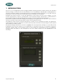
The Whisper Power System Control Panel (PSCP) consists of two combined modules: the generator
control (upper part), also referred to as DDC remote panel, and the Inverter/Charger Control panel
also referred to as RCC panel.
This Quick settings document is meant to highlight the most important settings to cover 90% of the
installations and user first needs. For an explanation to operation the PSCP or complete settings of
the WPC, please refer to the manual. Most of the settings are determined once at installation.
Settings which are likely to be changed by the user under normal use are highlighted in the
headings.
July 2012 / WPC / EN
3
SETTINGS
2 WPC – PSCP: QUICK START GUIDE
The remote control RCC gives you access to a many settings possibilities. However, in most cases the
setting of two parameters only is required for the perfect running of your installation.
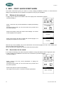
2.1
SETTING OF THE LANGUAGE
To begin, set your remote control PSPC / RCC for a display of the information in English.
The basic display is:
Press 1 time on the key “arrow downwards” to display the following
screen:
Once beyond this screen you can come back to it by means of the
key ”arrow upwards”.
Press the key SET to enter the remote control settings. The screen
of the language choice appears.
Press once more the key SET to modify the current language. The
language then appears in reverse video.
With the keys “arrow upwards” and “arrow downwards” choose the language you wish. Then validate your
choice by means of the key SET (OK).
We can now leave the setting of the remote control with the key ESC.
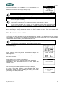
2.2
ADAPTATION TO THE SOURCE
It is a matter of indicating to the WPC the power available to charge the batteries and to supply the users.
In order to adapt your installation to the source it is connected to, proceed as follows:
The basic display is:
Press 2 times on the key “arrow downwards” to display the
following screen:
Once beyond this screen you can come back to it by means of the
key ”arrow upwards”.
Press the key SET to access to the settings.
Then again on the key SET to access to the basic parameters.
4
July 2012 / WPC / EN
SETTINGS
You can now adapt your installation to the source which it is
connected to.
Max. current of the AC source (Input limit) {1107}.
When an asterisk (*) is present, it informs you that the selected value corresponds to the
one set in factory by default (factory setting).
In case of using the WPC on a public grid, it is actually the value of the circuit breaker on the
source side (fuse or breaker).
In a building, this value lies generally between 8 and 16A.
In the case of a shorepower or of a camping terminal, it lies between 2 and 6A.
In case of using the WPC on a genset, you can divide the genset power by the operating
voltage (for instance for a genset of 3500VA, or 3500W, and 230V you get 3500/230=15.2).
Press the key SET to modify the value of this parameter (it appears in reverse video). By means of the keys
“arrow upwards” and “arrow downwards” change the value to adapt it to your source and validate your
setting with the key SET (OK).
2.3
ADAPTATION TO THE BATTERY
Charge current {1138}
In order that your WPC manages the best possible the energy stored in your batteries and that it charges
them optimally, it is necessary to indicate the current which they can be charged with. You will find this value
in the technical data provided by your batteries manufacturer.
In the case of lead-acid batteries, one generally uses one tenth or one fifth of the battery
capacity value.
For instance for a 500Ah battery: 500/10=50A to 500/5=100A.
The basic display is:
Press 2 times on the key “arrow downwards” to display the
following screen:
Once beyond this screen you can come back to it by means of the
key ”arrow upwards”.
Press the key SET to access to the settings.
Then again on the key SET to access to the basic parameters.
With the key “arrow downwards”, access the menu “Battery and
charger cycle”.
You are now going to set the charge current for the batteries:
Press the key SET to modify the value of this parameter (it appears
in reverse video). With the keys “arrow upwards” and “arrow
downwards” change the value to adapt your battery and validate
your setting with the key SET (OK).
July 2012 / WPC / EN
5
SETTINGS
3 BASIC DISPLAYS
When the remote control is connected to an WPC, it is possible to access to different display menus divided
into distinct categories.
Information on the system
The history of events occurring in the installation
Information
Real time information displays on the operating mode of the
installation
The different measures carried out by the BSP
(Only if a BSP is present)
Adjustment of RCC remote control options
Setting
Adjustment of configurations on the WPC(s)
The settings of the BSP
(Only if a BSP is present)
To go from one display to the other, use the keys UP and DOWN on the RCC remote control.
To visualize or modify the options of one of the basic displays, press the key SET when this one is displayed.
Depending on the components connected to your system, it is possible that other displays
complete this serie.
6
July 2012 / WPC / EN
SETTINGS
4 ACTIVATING AND DEACTIVATING THE WPC
When one of the displays is visible, it is possible to activate or deactivate the WPC. To do this, simply press
the key ESC. The key request on the screen indicates whether you are going to activate or deactivate the
unit.
Once the key has been pressed, you must confirm your choice
by using the key YES. If you do not want the action to be
carried out, it can be cancelled by pressing the NO key.
Note: This is a comprehensive signal and leads to the stoppage or starting of all WPC’s
connected to the remote control.
Putting ON or OFF the system can be easily done directly on the WPC with the button:
July 2012 / WPC / EN
7
SETTINGS
5 SETTING OF THE RCC REMOTE CONTROL
This screen gives you access to the remote control basic
settings. From one of the basic menu items, use the keys UP
and DOWN until reaching the item “Adjustment of the remote
control”, then confirm by using the key SET.
When the item to be modified appears on the screen, press the key SET to be able to modify it.
This value then displays in inverse video. Now use the keys UP and DOWN to modify it. Once
the correct value has been obtained, confirm by using the SET key or exit without modifying by
using the key ESC.
Each configuration has a unique ID displayed top right (see example below) these numbers
are indicated between curly brackets in this manual : {xxxx}
EXAMPLE to modify the current date
Go to the following screen using the UP and DOWN keys.
Press the key SET to access the remote control adjustment.
Go to the following screen using the key DOWN.
Press the key SET to modify the configuration
Set the correct date using the keys UP and DOWN
Go to the adjustment of the month using the key SET
Also set the month using the keys UP and DOWN
To complete, go to the year adjustment using the key SET
After having adjusted the year using the keys UP and DOWN,
confirm using the key SET.
5.1
SETTING OF THE LANGUAGE {5000}
The default language is English and the WPC can store up to four languages simultaneously. This
configuration allows you to choose one of them.
5.2
OTHER LANGUAGES {5036}
The default available languages in the remote control are: English, French, German and Spanish. It is
possible to change the languages memorized in the remote control. For this you must use a SD card with the
latest update available on our website (www.whisperpower.eu). Ask your reseller to know what languages
are available.
The first language available (English) can not be modified.
To change a language, follow this process:
Make sure you have a SD card with the file for the language you wish to use
Insert the SD card and wait for an possible automatical update of the remote control
Enter the menu „other languages“ {5036}
Choose the language you wish to replace (second, third or fourth {5038} {5039} {5040}) and select
the new language
The updating is done automatically
5.3
SETTING OF TIME {5001} AND DATE {5002}
The WPC has a perpetual calendar and an internal clock powered by a backup battery. The correct
adjustment of the date and time allows accurate recording of events occurring in the installation as well as
8
July 2012 / WPC / EN
SETTINGS
correct use of time-related functions, e.g. the disabling of the auxiliary relays during the night.
5.4
USER LEVEL {5012}
The setting of the user level allows you to choose the access to the WPC according to your level of
expertise.
The INFO ONLY level may be selected by entering the code:
460081
This level does not allow the WPC configurations to be modified, it only allows information to be displayed on
the system.
Use the INFO ONLY level after adjusting the configurations if the remote control is located
in a public place or if it is accessible by people who are not authorized to carry out
adjustments on your system.
You may change the level at any time to make new adjustments, by entering the appropriate
code.
The BASIC level allows you to configure basic WPC functions, limiting the field of actions to simple
configurations. Please note that the incorrect adjustment of basic configurations may lead to the
malfunctioning of the installation. This level is selected by default. To return to this level after a change, enter
code:
943274
The EXPERT level allows access to more complex WPC configurations and this level of usage may only be
used with extensive specialist knowledge. To access the expert level, enter code:
426468
5.5
DRIVE THE REMOTE CONTROL TO THE USER LEVEL BASIC {5019}
You can with this option bring the remote control back to the level “user Basic”.
Use this function at the end of the system setting to go out of the EXPERT mode.
July 2012 / WPC / EN
9
SETTINGS
6 BATTERY SETTINGS
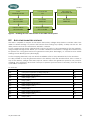
6.1
DEFAULT BATTERY SETTINGS
Different battery types require different settings which indicate if the battery is full or empty, for
protection values, for charge regulation and auto start/stop criteria. In the following table the
parameters are listed which are relevant when installing a battery set (multiply the value by 2 or 4,
for 24V and 48V sets):
Parame
AGM
ter
(default)
1138
1139
Battery charge current
Battery temperature compensation
Refer
GEL
to
Traction
2V 6x
Refer
to
Refer
Table 2
Table 2
Table 4
-4
-4
-4
to
Adc
mV/°C/
cell
1108
Battery undervoltage level without load
11.6
11.6
11.6
Vdc
1109
Battery undervoltage level at full load
10.5
10.5
10.5
Vdc
1190
Battery undervoltage duration before turn off
3
3
3
min
1110
Restart voltage after batteries undervoltage
12
12
12
Vdc
1196
Battery low level for acoustic alarm
10.8
10.8
10.8
Vdc
1195
Max voltage for adaptive low voltage
12.5
12.5
12.5
Vdc
1307
Reset voltage for adaptive correction
13.2
13.2
13.2
Vdc
1298
Increment step of the adaptive low voltage
0.1
0.1
0.1
Vdc
1121
Battery overvoltage level
17
17
17
Vdc
1122
Restart voltage level after an battery overvoltage
16.2
16.2
16.2
Vdc
1140
Battery floating level
13.6
13.6
13.5
Vdc
1143
Battery voltage level 1 to start a new cycle
12.5
12.5
12.5
Vdc
1144
Time period under battery voltage level 1 to start a new cycle
30
30
30
min
1145
Battery voltage level 2 to start a new cycle
12.3
12.3
12.3
Vdc
1146
Time period under battery voltage level 2 to start a new cycle
60
60
60
sec
1149
New cycle priority on absorption and equalization phases
No
No
No
No/Yes
1155
Absorption phase allowed
Yes
Yes
Yes
No/Yes
1156
Battery absorption voltage
14.4
14.4
14.1
Vdc
1157
Absorption duration
2
2
2
hours
1158
End of absorption triggered with current
Yes
Yes
Yes
No/Yes
1159
Current limit to quit the absorption phase
Refer
Table 2
to
Refer
Table 3
to
Refer
to
Adc
Table 4
Table 1 – Battery settings
10
July 2012 / WPC / EN
SETTINGS
AGM
55Ah
80Ah
100Ah
145Ah
200Ah
260Ah
1138*
16.5A
24.0A
30.0A
44.0A
60.0A
78.0A
1159
4A
4A
10A
10A
10A
10A
Parameter
Table 2 – AGM battery settings according to capacity
GEL
100Ah
145Ah
180Ah
225Ah
1138*
20.0A
29.0A
36.0A
45.0A
1159
4A
6A
10A
10A
Parameter
Table 3 - GEL battery settings according to capacity
Traction
600Ah
800Ah
1000Ah
1200Ah
1500Ah
1138*
240A
320A
400A
480A
600A
1159
10A
10A
10A
10A
10A
Parameter
Table 4 - Traction battery settings according to capacity
* Note: the maximum setting of parameter 1138 will be equal to the maximum of the battery
charge current which the specific WPC model can provide.
6.2
BATTERY TEMPERATURE SENSOR (BTS)
The temperature sensor is available as option. It must be connected to the BTS input on the WPC.
The following setting is relevant when using a BTS.
Parameter
Name
Default
1139
Battery temperature compensation
-4
6.3
mV/°C/cell
BATTERY STATUS INDICATOR (BSI)
When the BSI is connected, the state of the battery is not monitored by voltage only. The BSI
estimates the actual capacity of the connected battery and the state of charge by measuring the
current with the installed shunt. If the BSI is connected, it is also possible to automatically start and
stop the generator according to the state of charge. Refer to the auto start paragraph for the BSI
settings
Installation of the BSI is described in its own manual.
July 2012 / WPC / EN
11
SETTINGS
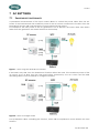
7 AC SETTINGS
7.1
SMART BOOST FUNCTIONALITY
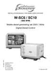
A permanent measurement of the input current allows to control the power taken from the AC
source. If the load exceeds the maximum power of the AC source connected to the WPC then the
Smart-Boost function will compensate the power required at the output.
For example if the max power of the ac generator is set at 3kW but the load is 4kW, then 3kW is
taken from the generator and 1kW is taken from the battery.
{1107}
{1566}
{1567}
Figure 1 - WPC using the Smart-Boost function
If the load is only 1kW, then the Smart-Boost function will not be used. If the maximum power of the
ac source is set at 3kW, then the 1kW load will be powered by the AC source and the 2kW
remaining will be used as needed to charge the battery.
{1107}
{1566}
{1567}
Figure 2 - WPC in charger mode
Four parameters allow controlling this function, which will be explained in more detail in the next
sections:
12
July 2012 / WPC / EN
SETTINGS
Parameter
Name
Default
1126
Smart Boost allowed
Yes
└> authorize the use of the Smart Boost function. Set as YES
Parameter
Name
Default
1566
Use an alternate max. input current
Yes
└> authorize the use of a second energy source at the input of the system. Set as YES
Parameter
Name
Default
1107
Maximum current of AC source (Input limit)
16A
└> is the value of the input current which can be drawn from the grid. Set according to the size of
the circuit breaker or the grid capacity.
Parameter
Name
Default
1567
Second maximum current of AC source (Input limit)
13A
└> is the value of the input current which can be drawn from the generator. Set according to the
size of the circuit breaker or the generator capacity.
7.2
AC INPUT
7.2.1 User setting: Quick setting of the max current of the ac source
Once a system is installed at a fixed location, there is normally no need to change WPC input
settings but users of mobile applications have to change the input current when the installation is
moved. To ease the use of the WPC for these customers, there is on the RCC a “one button push”
access to the parameter {1107} from the default screen. By pressing the SET button it directly goes
to the max current of the ac grid source value and it is possible to increase or decrease it with the
up or down button.
Parameter
Name
Default
1107
Maximum current of AC source (Input limit)
16
A
Figure 3- Fast access to set the max current of the ac grid source
7.2.2 Setting of the max current of the ac generator
In the variable speed system GV-7i, the input current limit setting determines the maximum power
taken from the generator. By default, the power taken from the generator is limited to 13A (3KW).
Parameter
1567
1567
1567
1567
1567
Name
Second maximum current of AC source (Input limit)
Second maximum current of AC source (Input limit)
Second maximum current of AC source (Input limit)
Second maximum current of AC source (Input limit)
Second maximum current of AC source (Input limit)
Default
13
11
22
22
16 – 25
A
A
A
A
A
Model
GV-7i
SC-3.5
SQ-6
SC-6
If genset power is > 25A, install fuse
of 25A or less and limit accordingly.
25A is the maximum current which can be allowed as input on the WPC, either generator input or
Grid input.
July 2012 / WPC / EN
13
SETTINGS
7.2.3 Allow to overrun the maximum input current of the AC source
“Overrun AC source current limit without opening the transfer relay (Input limit)” {1436}. This
parameter is set at “YES”; it means that if the power requested is more than can be delivered by
the Smart-Boost, the AC input grid current will go over the programmed max input limit value. In
case the limit was set to a low value because of low generator speed, it means that more power
will be taken from the generator and it will speed up. Keep in mind however that the generator
output power is limited by the engine power and if more than its max power is used, the generator
will stop on overload.
If a AC grid line (or shore input) is overloaded, the circuit breaker may blow.
Parameter
Name
Default
1436
Overrun AC source current limit without opening the transfer relay
No
For example, the requested output power is 15A. Parameter 1567 is set to 13A. Then 13A will be
delivered by the generator and 2A Smart-boosted byu the inverter. If parameter 1567 is set to 6A,
then 6A will be delivered by the generator and 9A Smart-boosted by the inverter. Now if the
requested output goes up to 25A, the Smart-boost power is limited to 15A and because parameter
1436 is set to ‘Yes’, the power delivered from the generator (or grid input) will be 10A, possibly
blowing a 6A fuse in case of grid input. Would the parameter be set to ‘No’, then the system will
stop on ‘overload’ and a 6A fuse would not be blown.
7.2.4 Automatic selection of AC source
The WPC has an automatic switching AC input on the connection board. If the generator is
running, it is used as the primary AC source. Otherwise the switches will be in the position to allow
AC grid input power. Four situations can occur:
Situation 1:
14
Power is delivered from the AC grid (limit set by parameter 1107)
The battery is automatically charged
July 2012 / WPC / EN
SETTINGS
Situation 2:
The AC sources are disconnected
The battery is supplying energy to the AC output through the inverter
Situation 3:
Power is delivered from the AC generator (limit set by parameter 1567)
The battery is automatically charged
Situation 4:
Both AC sources are available
The AC output is supplied by the preferred AC source (see page 24 for settings)
The battery is automatically charged
July 2012 / WPC / EN
15
SETTINGS
7.3
AC OUTPUT
The WPC has an continuous AC output “Gen/Grid/Inv”. It also has an switched AC output which is
named Gen/Grid both located at the output board. This Gen/Grid output is switched on only when
there is a valid AC input available. Figure 4 shows the AC output state when no AC input is
available.
Gen/Grid/Inverter
Gen/Grid : no output
Figure 4 – AC out with no AC input available
Figure 5 shows the situation when there is AC input available, note that both the GGI and GG
output are now active.
Gen/Grid/Inverter
Gen/Grid
Figure 5 - AC out with AC input available
Connect devices which should not be powered by the batteries to the Gen/Grid output, such as
boilers, battery chargers etc.. In case of an AC input loss, these devices will not drain the batteries
because they are switched off automatically.
The state of the Gen/Grid output can be overruled by parameter [1311] “Operating mode AUX 2”,
it can be set to Off, On, Automatic and Reversed Automatic. The default setting is automatic.
Parameter
Name
Default
1311
Operating mode (Aux 2)
Automatic
If this parameter is set to On, then the Gen/Grid output will always be on, just like the
Gen/Grid/Inverter output. If it is set to ‘Off’, there will never be AC output on the Gen/Grid AC
output. If set to ‘Reversed Automatic’ then the Gen/Grid AC output will be on when there is no AC
input(!) and Off when there is AC input.
16
July 2012 / WPC / EN
SETTINGS
7.4
AC GENERATOR BEHAVIOR
The output power of a variable speed generator depends directly on the speed of the engine.
When the engine speed is too low for the power demand, the engine must increase its speed. The
output voltage of the generator is temporarily decreased. To ensure a stable AC voltage at the
output and to enable the engine to rev up, a permanent measurement of the input AC voltage is
done by the WPC. The drop voltage is detected and the input current of the WPC is lowered to
stabilize the voltage. Thereafter, the Smart-Boost function is used to help the generator with the
necessary power. With that association, constant power is available even when the generator is
running at low speed.
Parameters & descriptions
The following parameters allow controlling this function:
Parameter
Name
Default
1567
Second maximum current of AC source (Input limit)
13A
└> is used to set the maximum current the generator can give.
Example for an generator of 3500W / 230Vac = 15Aac
Parameter
Name
Default
1554
Decrease max input limit activated by remote entry
Yes
└> activates the function that decreases the max input limit current with the generator AC voltage.
Parameter
Name
Default
1126
Smart-Boost allowed
Yes
└> helps the generator by adding the missing power when the motor speed is too low.
Parameter
Name
Default
1309
AC input low limit voltage to allow charger function
220V
└> is the lowest input voltage (where the input current of the generator must be set at 0).
Parameter
Name
Default
1433
Adaptation range of the charge current according to the input voltage
5V
└> is the range of voltage between whom the current will be adapted.
Parameter
Name
Default
1435
Immediate detection of input voltage loss
Tolerant
└> Allows to starting the inverter mode as quick as possible in case of fluctuations of the AC-in grid.
This function is useful when it comes to very sensitive loads that require an uninterruptible power
supply (UPS).
Parameter
Name
Default
1575
AC-IN current active filtering
Yes
└> regulates smooth power demand from the generator (or grid) which allows slow increase and
decrease of the speed of the engine.
Principle of operation of parameter “Decrease max input limit current with AC-In voltage”
The max input current {1107} is decreased down to 0 at the {1309} voltage over a range given by
the parameter {1433}. (See figure 2). The recommended values are 210V for the limit voltage {1309}
and 10V for the voltage hysteresis {1433}. Thus, from 220V the max input current is decreased down
and is at 0 when the voltage is at 210V. In this way, the WPC helps the generator when it can’t
provide enough power on account of a low-speed engine, to allow it to increase its speed.
July 2012 / WPC / EN
17
SETTINGS
Figure 6 - Principle of the decrease of max input current
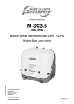
Output Power
GV7i - Power Chart
8000
7000
6000
5000
4000
3000
2000
1000
0
Combined Power
WPC power
Generator Power
RPM generator
Figure 7 - Variable speed generator power curve and representation of ensured constant power
and additional system power.
Note: Data shown in the figure is indicative and does not represent the actual power curve in the
GV-7i situation.
7.5
USER SETTINGS: CONTROLLING THE VARIABLE SPEED GENSET POWER DEMAND
To enable a smooth and constant power demand of the generator of the GV-7i, the following
parameters are set:
Parameter
Name
Default
1567
Second maximum current of AC source (Input limit)
13A
1575
AC-IN current active filtering
Yes
1436
Overrun AC source current limit without opening the transfer relay
No
1138
Battery charge current
45
The AC-IN active filtering function ensures that the power demand upon the genset does not
change abruptly. It does this by Smart-boosting in case of a sudden load increase, or by charging
the batteries in case of a sudden switch off of the load. Furthermore it tries to get the current and
voltage of the AC input in phase as much as possible.
However, the AC-IN active filtering function can only boost up to 100% of its max power, which is
18
July 2012 / WPC / EN
SETTINGS
15A in the 24V model. In case of bigger load steps, the remaining power needed will be drawn
from the generator. Also, the AC-IN active filtering function regulates only within the ac-input limit
current range. In case AC-overrun is allowed (by default it is not allowed), it means that the AC-IN
active filtering does not work if more current is drawn from the generator than set at the input
current limit.
How to set these parameters may be a bit of experimenting. The main constraint is the type of load
that is connected to the system:
1. When relatively big load steps are made (e.g. >2kW loads) regularly such as a heavy water cooker
or vacuum cleaner, on top of a base load, it is best to set the input limit of the generator to a higher
value, e.g. 10A or more (but not more than the max the generator can deliver).
2. If only small load steps are made (<1kW) such as chamber lights, computer etc.. with or without a
base load, the input current limit can be set to a lower value to limit the engine speed of the
generator, and set the ‘Overrun AC source current limit’ parameter to Yes.
If lowest operating speed of the generator is desired, two options are available:
1. Set the charging current to 40A or less. When the only load of the generator is the charger, 40A will
make sure that the generator is running constantly at its lowest speed. The default is set to 40A
because the charge current is also limited by the size of the battery, and 40A is allowed with the
minimum set that is usable for the GV-7i.
2. The input limit current can be set to 6A. This causes the generator to operate at its lowest speed,
and if additional power at the output is needed (>1300W), it is Smart boosted by the WPC.
However, if there is a base load of around 1kW or more and heavy loads (e.g. 3kW) are switched on,
this will lead to a sudden load step upon the generator which causes a sudden increase in speed.
Also, to be able to supply use the total power of the system in this case, the ‘Overrun AC source
current limit’ must be set to Yes.
Option 1 is preferred.
July 2012 / WPC / EN
19
SETTINGS
8 USER SETTING: AUTO START SETTINGS
Automatic start/stop is regulated by three main categories:
1. Battery state
2. AC power consumption
3. Silent times
Firstly, the automatic mode must be chosen on the DDC remote panel !
The automatic starting and stopping is controlled by switching on and off a signal on the DDC
remote panel ‘auto start’ input. This signal is applied by the connection board on the WPC. Take
care that the red wire of the cable is connected to the + pole of the connector, and the black wire
to the – pole. Furthermore it is necessary to connect the both negative poles of the starter battery
and the WPC battery. This is needed for correct functioning of the auto start function.
Figure 8 – Auto start connection
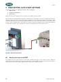
8.1
ENABLE AUTO START ON THE DDC
To enable the auto start function on the DDC control panel, go to the “select menu” using the
select button. Then choose for the “auto start menu” and enable the “Auto start on switch” item. If
needed first unlock the settings. Figure 9 shows the menu settings to make.
20
July 2012 / WPC / EN
SETTINGS
GVxi
STANDBY-MODE
SELECT MENU
SET TO ENTER
LOCK MODE
OFF
EXT. SWITCH
AUTOSTART ON
EXIT MENU
OFF
PRESS SET
Sdadads
ds
EXIT MENU
PRESS
SET
sdadads
AA
DISPLAY MENU
SET TO ENTER
AUTO START MENU
OFF
SET TO ENTER
OFF
ON
Figure 9 – Enabling the auto start function on the DDC remote panel
8.2
AUTO START ON BATTERY VOLTAGE
The WPC is capable to request a start when the battery voltage drops below a certain value. See
table for default settings. To prevent this function from acting very rapidly, a delay can be set. This
delay can be set from 0 to 60 minutes, default is 1 minute.
For the starting mode three voltage levels can be set, refer to the parameter list for the numbers.
Using multiple voltage levels allows you to make a difference between a voltage level which must
be present for a long time before the generator starts (slow discharge), or a lower level at which
starting occurs directly (heavy discharge).
For the stopping threshold, only one level is available, refer to the parameter list for the numbers.
It is also possible to stop the generator when is the battery state has reached float; this is a state to
top off the battery charge and take only low current. When the generator power is only used for
charging, this is inefficient. Note that if AC input is present (not because of autostart), then the float
cycle will be completed.
To activate:
Parameter
Name
Default
1288
Use dynamic compensation of battery level (AUX 1)
Yes
1246
Battery voltage 1 activate (AUX 1)
Yes
1247
Battery voltage 1 (AUX 1)
11.8
1248
Delay 1 (AUX 1)
1
1249
Battery voltage 2 activate (AUX 1)
Yes
1250
Battery voltage 2 (AUX 1)
12
1251
Delay 2 (AUX 1)
10
1252
Battery voltage 3 activate (AUX 1)
Yes
1253
Battery voltage 3 (AUX 1)
12.2
1254
Delay 3 (AUX 1)
60
July 2012 / WPC / EN
21
SETTINGS
To deactivate:
Parameter
Name
Default
1255
Battery voltage to deactivate (AUX 1)
13.6
1256
Delay to deactivate (AUX 1)
120
1516
Deactivate if battery in floating phase (AUX 1)
Yes
8.3
AUTO START ON BATTERY SOC (ONLY WITH BSI)
The BSI monitors the state of charge(SOC) of the battery. This is the percentage of the remaining
battery energy. The WPC is able to start the generator according to this state of charge.
Parameters for configuring this function are shown below.
To activate:
Parameter
Name
Default
1439
Contact activated with the SOC 1 of battery (AUX 1)
No
1440
Contact activated below SOC 1 (AUX 1)
50
1581
Delay 1 (AUX 1)
12
1582
Contact activated with the SOC 2 of battery (AUX 1)
No
1583
Contact activated below SOC 2 (AUX 1)
30
1584
Delay 2 (AUX 1)
.25
1585
Contact activated with the SOC 3 of battery (AUX 1)
No
1586
Contact activated below SOC 3 (AUX 1)
20
1587
Delay 3 (AUX 1)
0
To deactive:
Parameter
Name
Default
1441
Contact deactivated over SOC (AUX 1)
90
1588
Delay to deactivate (AUX 1)
.25
1589
Deactivate if battery in floating phase (AUX 1)
Yes
8.4
AUTO START ON AC OUTPUT POWER
The WPC is capable of request a start when the AC output power is exceeding a certain value. This
value is a percentage of the nominal power of the WPC (Pnom). By default 70% of Pnom (3000W
for the 24V version) which is 2100W. To prevent this function from acting very rapidly, a delay can
be set. This delay can be set from 0 to 60 minutes, default is 1 minute.
Using multiple power levels allows you to make a difference between a power level which must be
present for a long time before the generator starts, or a higher level at which starting occurs directly
(heavy
load,
immediate
assistance
needed).
For the stopping threshold, only one level is available, refer to the parameter list for the numbers.
To activate:
Contact active with inverter power or Smart-Boost (AUX 1)
Default
1258
Inverter power level 1 activate (AUX 1)
Yes
No/Yes
1259
Power level 1 (AUX 1)
70
% Pnom
1260
Time delay 1 (AUX 1)
15
min
22
July 2012 / WPC / EN
SETTINGS
1261
Inverter power level 2 activate (AUX 1)
Yes
No/Yes
1262
Power level 2 (AUX 1)
100
% Pnom
1263
Time delay 2 (AUX 1)
5
min
1264
Inverter power level 3 activate (AUX 1)
Yes
No/Yes
1265
Power level 3 (AUX 1)
110
% Pnom
1266
Time delay 3 (AUX 1)
1
min
To deactive:
Contact active with inverter power or Smart-Boost (AUX 1)
Default
1267
Inverter power level to deactivate (AUX 1)
40
% Pnom
1268
Time delay to deactivate (AUX 1)
5
min
8.5
ENABLE A SILENT PERIOD
To prevent the generator from automatically starting within a specified period (e.g. at night), it is
possible to set a silent period. Setting a silent period is done using the program parameters of the
AUX 1 signal. Below are the parameters listed, in total you can set 5 different programs.
1203
Temporal restrictions (AUX 1)
1204
Program 1 (AUX 1)
1205
Day of the week (AUX 1)
default
-- -- -- -- -- -
Days
- -1206
Start hour (AUX 1)
07:00
hh:mm
1207
End hour (AUX 1)
20:00
hh:mm
1208
Program 2 (AUX 1)
-- -- -- -- -- -
Days
1209
Day of the week (AUX 1)
- -1210
Start hour (AUX 1)
07:00
hh:mm
1211
End hour (AUX 1)
20:00
hh:mm
1212
Program 3 (AUX 1)
-- -- -- -- -- -
Days
1213
Day of the week (AUX 1)
- -1214
Start hour (AUX 1)
07:00
hh:mm
1215
End hour (AUX 1)
20:00
hh:mm
1216
Program 4 (AUX 1)
-- -- -- -- -- -
Days
1217
Day of the week (AUX 1)
- -1218
Start hour (AUX 1)
07:00
hh:mm
1219
End hour (AUX 1)
20:00
hh:mm
1220
Program 5 (AUX 1)
-- -- -- -- -- -
Days
1221
Day of the week (AUX 1)
July 2012 / WPC / EN
23
SETTINGS
- -1222
Start hour (AUX 1)
07:00
hh:mm
1223
End hour (AUX 1)
20:00
hh:mm
Important: the period cannot be set over midnight. If the required silent time is e.g. from 22.00pm till
7.00am, then two periods have to be programmed.
Period 1 start hour: 22.00, end hour: 24.00
Period 2 start hour: 00.00, end hour: 7.00
It is also possible to automatically start on fixed intervals instead of upon load or battery demand.
This is however not typical for the GV-7i installation. Refer to manual for details.
8.6
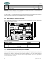
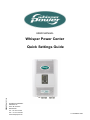
USER PREFERENCE: DIPSWITCH FUNCTIONS
To set the behavior of the input switching component of the WPC a dipswitch is available at the
input switching board. To access it, open the connection compartment cover. The figure below
show the location of the dipswitch.
Figuur 10 – Dipswitch location
Dipswitch
Function
Default
1
Prohibit automatic start when grid is available
Off
2
Preferred input
On
ON = Generator
Off = Grid
8.6.1 Prohibit automatic start when grid is available
Default the generator will automatically start when one of auto start criteria is met. It starts even
when the is AC grid is connected. In some cases the AC grid can supply more power than the
generator. In this situation it is most likely that starting of the generator is not wanted. To prohibit the
generator from starting in this situation set the upper dipswitch to the “ON” position. Now the
Autostart signal will indicate “start” only when there is no grid available. Refer to the figure above
for the position of the dipswitch.
24
July 2012 / WPC / EN
SETTINGS
8.6.2 Preferred input
When both AC inputs are available, this setting will determine which AC input is passed through for
power delivery.
July 2012 / WPC / EN
25
NOTE
9 NOTES
26
July 2012 / WPC / EN
SETTINGS
July 2012 / WPC / EN
27
Kelvinlaan 82, 9207 JB Drachten, Netherlands
Tel : + 31-512-571550 / Fax : + 31-512-571599
www.whisperpower.eu / [email protected]