1
Monarch®
9855® RFID
Printer
TC9855RFIDMPAN Rev. AJ 9/08
©2005 Paxar Americas, Inc. a subsidiary of Avery Dennison Corp. All rights reserved.
Each product and program carries a respective written warranty, the only
warranty on which the customer can rely. Paxar reserves the right to
make changes in the product, the programs, and their availability at any
time and without notice. Although Paxar has made every effort to provide
complete and accurate information in this manual, Paxar shall not be
liable for any omissions or inaccuracies. Any update will be incorporated
in a later edition of this manual.
2005 Paxar Americas, Inc. a subsidiary of Avery Dennison Corp. All
rights reserved. No part of this publication may be reproduced,
transmitted, stored in a retrieval system, or translated into any language
in any form by any means, without the prior written permission of Paxar
Americas, Inc.
W ARNING
This equi pment has been tested and found to comply wi th the limi ts for a Clas s A digital device,
pursuant to Part 15 of the FCC Rules. These limits are designed to provide reas onable
protecti on agai nst harmful interference when the equi pment is operated in a commercial
environment. This equi pment generates , uses, and can radi ate radio frequency energy and, if
not installed and used in accordance with the instruction manual , may caus e harmful
interferenc e to radio communications . Operation of this equipment in a resi dential area is lik el y
to caus e harmful interference in which case the us er wi ll be requi red to correct the interference
at his own expense.
C AN ADI AN D.O.C. W ARNING
This di gi tal apparatus does not exceed the Cl ass A limits for radi o noise emissions from di gital
apparatus set out in the Radi o Interference Regulati ons of the Canadian Department of
Communications.
Le prés ent appareil numéri que n'émet pas de bruits radioélectriques dépassant les limites
applicables aux appareils numéri ques de la clas se A prescrites dans le Réglement sur le
brouillage radi oélectri que édicte par le ministère des Communications du Canada.
Trademarks
Monarch and 9855 are trademarks of Paxar Americas, Inc.
Avery Dennison is a trademark of Av ery Denni son Corp.
EPCgl obal , Inc . and Elec tronic Product Code™ (EPC) are trademarks of Uniform Code Council,
Inc. Uniform Code Council, Inc. is a trademark of Uniform Code Council, Inc.
Symbol and Matrics are trademarks of Symbol Technologies, Inc.
Avery Dennison Printer Systems Di vision
170 Monarch Lane
Miamisburg, OH 45342
TA B L E O F C O N T E N T S
GETTING STARTED ......................................................................................1-1
Using This Manual ...................................................................................1-1
Audience ................................................................................................1-2
About Transponder Types.........................................................................1-2
RFID Terms to Know ................................................................................1-3
RFID Considerations ................................................................................1-4
MULTI-PROTOCOL ENCODING .....................................................................2-1
About RFID Supplies................................................................................2-1
Using the RFID Setup Menu......................................................................2-1
Read Tag ............................................................................................2-3
Write Retries .......................................................................................2-4
Signal Adjust .......................................................................................2-5
RF Power (Read/Write Settings) ............................................................2-6
Clear Data ...........................................................................................2-7
Print Configuration Label ......................................................................2-8
Protocol ..............................................................................................2-9
SETTING UP THE PRINTER ..........................................................................3-1
Setting the Print and Supply Positions .......................................................3-1
Using the Setup Supply Menu ...................................................................3-1
Setting the Supply Type ........................................................................3-3
Setting the Error Action ........................................................................3-4
Version Information .................................................................................3-7
Additional Font ........................................................................................3-8
Table of Contents i
DEFINING THE RFID DATA FIELD................................................................. 4-1
Applying Options to the RFID Data Field ................................................... 4-3
Using Option 5 (Define Data Entry Sources) .............................................. 4-4
Using Option 6 (Upload Field Data)........................................................... 4-5
Sample Upload Packet ......................................................................... 4-6
Using Option 30 (Pad Data) ..................................................................... 4-8
96-Bit RFID Data Field Examples.............................................................. 4-9
Using Expanded Gen2 Data ................................................................... 4-14
TROUBLESHOOTING ................................................................................... 5-1
RFID Errors......................................................................................... 5-2
INDEX ............................................................................................................. i
ii Multi-Protocol Application Notes
1
G E T T I N G S TA R T E D
Your Monarch 9855 RFIDMP (Radio Frequency Identification
Multi-Protocol) printer has been engineered to program (encode) an RFID
label (commonly called “RFID tags”) before the label’s format is printed.
RFID tags contain an embedded RFID inlay (chip and antenna).
RFID is only available using die cut or black mark supplies. Linerless
supplies are not currently supported. The RFID printer is also capable of
printing standard (non-RFID) supplies. For more information about
supplies, see “About RFID Supplies.”
The printer supports multi-protocol encoding, including Class 1
Generation 1 (C1Gen1), Class 1 Generation 2 (C1Gen2), and EM4122
supplies.
Note:
Information in this document supercedes information in previous
versions.
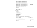
Using This Manual
The following table lists the contents of this manual.
Chapter
Contents
1
Getting Started
Information you should know before using the printer.
2
Multi-Protocol
Encoding
Using the RFID menu to setup the printer and select
a protocol. Also includes information about RFID
supplies.
3
Setting Up the
Printer
Using the Setup menu to select an overstrike mode
for the printer.
4
Defining the RFID
Data Field
Using Monarch Printer Control Language II
(MPCLII) to create an RFID format. Also includes
sample data streams.
5
Troubleshooting
Describes RFID errors that may occur.
Use the RFID Quick Reference (provided with your printer) for supply
loading and maintenance information.
Getting Started 1-1
Refer to the RFID Setup Guide & Supply Chart for illustrations to
determine which type of RFID supplies you are using and basic printer
configuration information
Audience
These RFIDMP Application Notes are written for the System
Administrator, who is creating formats for the 9855 multi-protocol printer.
About Transponder Types
The following table describes the transponder types.
Transponder Type
Description
Class 0
A type of transponder that allows read and
write capability with 96-bits.
Class 0+
A type of transponder that allows read and
write capability with 96-bits.
Class 1 Gen1 or
Class 1 Gen2
A type of transponder that allows read and
write capability with 64 or 96-bits.
The RFID supplies are sensitive to static electricity and can be
damaged by static electricity. Ground yourself by touching some
metal, such as the printer’s metal base, before handling the
supplies.
1-2 Multi-Protocol Application Notes
RFID Terms to Know
Review these terms before you continue.
EPC
The Electronic Product Code, which is a numbering
standard for items, similar to the UPC code for bar
coding. The EPC is divided into several sections:
Header, Manager Number, Object Class, and Serial
Number.
One of the memory fields reserved for EPC programming.
This memory is separate from the user memory and the
amount of EPC memory varies with the tag types.
Inlay
A type of media that contains a transponder and is
converted for use in Monarch® RFID supplies (tags).
Inlays can be made with different types of transponders
(Class 0, Class 1, etc.).
Interrogator
The electronics module that programs the RFID tags
through the antenna.
RFID Data
Field
The Monarch Printer Control Language II (MPCLII) data
field containing the information to program into an RFID
tag.
RF Field
Area inside the printer where the RFID tag is
programmed. The RF field area is controlled by the RFID
power level and the antenna.
Note: The printer’s antenna is located between the
platen roller and supply guide inside a bracket.
RFID Power
Increases the strength of the RF field emitted by the
printer’s antenna to read and program the RFID tags.
RFID Reader
An optional external device that reads the RFID tags
after they are programmed.
RFID Tags
Supplies that contain an embedded programmable chip
and antenna.
TID
The Transponder Identification Number, which contains
the chip type, features, and available custom commands
supported for tag authentication.
Getting Started 1-3
Transponder
The combination of the embedded programmable chip
with an antenna on some type of media (film, paper,
etc.). Different types of transponders are available
(Class 1 Gen1 or Class 1 Gen2).
User Memory
One of the memory fields reserved for user programming.
This memory is separate from the EPC memory and the
amount of programmable user memory varies with the tag
types.
RFID Considerations
♦
Printing over the RFID tag (or inlay) causes printing irregularity.
♦
You may want to purchase an RFID Reader to verify the RFID tags
after printing them.
♦
Do not use batch separators, which prints a pinstripe pattern on a
label; or skip index mode, which prints ONE format over multiple
labels, since these features unnecessarily waste a label. A batch
separator label is different from an overstrike label.
1-4 Multi-Protocol Application Notes
2
M U LT I - P R O T O C O L E N C O D I N G
This chapter contains specific information for the multi-protocol
printer, including using the RFID, Setup Menu.
About RFID Supplies
RFID supplies are available in a variety of sizes. Printing over the RFID
tag (or inlay) causes printing irregularity. Refer to the RFID Setup Guide
& Supply Chart for illustrations to determine which type of RFID supplies
you are using and basic printer configuration information.
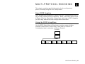
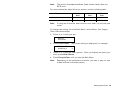
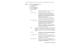
Using the RFID Setup Menu
Use the RFID Setup Menu to Read a tag, set the number of Write
Attempts, Read Power, Write Power, Clear Data, print an RFID
Configuration label, and select a different Protocol.
MAIN MENU
S e tup
R F ID
Read
T ag
Write
Retries
Signa l
Adjust
RF
Powe r
Clear
D a ta
Prin t
Config
Protocol
Multi-Protocol Encoding 2-1
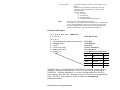
Option
Choices
Default
Read Tag
NA
NA
Write Retries
1-5
3
Signal Adjust
0-6
2
RF Power
Read Power 1-25/
Write Power 1-25
18
Clear Data
Yes/No
No
Print Config
Yes/No
No
Protocol
C1Gen2
C1Gen1 96
C1Gen1 EPC64/96
EM4122
C1Gen2
When you turn on the RFID printer, “Monarch Initializing” flashes briefly
and then you see “Print Mode Ready.” If an error occurs while the printer
is initializing, the error message flashes briefly on the display and then
you see “Print Mode Ready.” The printer displays “Not available” when
you try to select the RFID menus if the module is inoperative.
The printer accepts RFID and non-RFID batches once you see “Print
Mode Ready.”
2-2 Multi-Protocol Application Notes
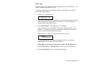
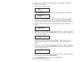
Read Tag
Use this option to read the EPC data programmed into an RFID tag. You
cannot read the user memory data.
To change the setting, from the Main Menu, select Setup, then RFID.
Then follow these steps.
1.
Press
or
until you see
RFID
Read Tag
2.
Lay the RFID tag you just programmed inside the supply path with the
tag’s antenna over the printer’s box antenna. (The box antenna is
located behind the platen roller.)
3.
Press Enter/Pause. Data appears on the display.
If the tag cannot be read “Illegal Command” appears briefly on the
display. Try slightly moving the tag forward or back in the supply
path over the box antenna and try again.
If the tag can be read, you see the EPC data, such as
Complete
0123456789ABCDEF
The programmed data is always displayed in ASCII Hex format,
regardless of which data type was entered.
Press
to scroll through the data (if using a 96-bit RFID tag).
Press Enter/Pause or Escape/Clear to return to the RFID Menu.
4.
Press Escape/Clear until you see the Main Menu.
Multi-Protocol Encoding 2-3
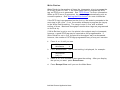
Write Retries
Write Retries is the number of times the interrogator tries to program the
RFID tag in the RF Field. If the interrogator fails to program the RFID
tag, an RFID error is generated. See “RFID Errors” for more information.
When an RFID error is generated, the printer may automatically print an
overstrike pattern. See “Setting the Error Action” for more information.
If the RFID tag is programmed on the first try, the module proceeds to the
next step in the cycle. If not, the module attempts to program the tag up
to the Write Retries setting. The range is one to five, with a default
setting of three. Maximum throughput results when tags are programmed
on the first try.
If Write Retries is set to one, the printer’s throughput may be increased;
however, a good RFID tag may be reported as not programmable. If
Write Retries is set to five, the printer’s throughput may be decreased;
however, the number of RFID tags programmed may or may not increase.
1.
Press
or
until you see
RFID
Write Retries
2.
Press Enter/Pause. The current setting is displayed, for example:
Write Retries?
[1/5]: +3
3.
Press
or
to increase or decrease the setting. After you display
the option you want, press Enter/Pause.
4.
Press Escape/Clear until you see the Main Menu.
2-4 Multi-Protocol Application Notes
Signal Adjust
Use the Signal Adjustment to increase the strength of the RF Field
emitted by the printer’s antenna. The higher the value, the greater the
power of the RF Field.
When using the read-only EM4122 protocol, the settings for Write Power
and Signal Adjust are ignored.
CAUTION:
Use extreme caution when changing the Signal Adjustment
because the RFID tags may become non-functional!
To change the setting, from the Main Menu, select Setup, then RFID.
Then follow these steps.
1.
Press
or
until you see
RFID
Signal Adjust
2.
Press Enter/Pause. The current setting is displayed, for example:
SIGNAL ADJUST
[0/6]: +2
3.
Press
or
to increase or decrease the setting. After you display
the option you want, press Enter/Pause.
4.
Press Escape/Clear until you see the Main Menu.
Multi-Protocol Encoding 2-5
RF Power (Read/Write Settings)
Use the RF Power menu to set the Read and Write power settings. The
Read and Write Power settings increase the strength of the RF Field
emitted by the printer’s antenna. The higher the value, the greater the
power of the RF Field.
If either the Read or Write Power settings are too high or too low, you
may not be able to read the tags or you may change the data that was
programmed in to adjacent RFID tags.
When using the read-only EM4122 protocol, the settings for Write Power
and Signal Adjust are ignored.
CAUTION:
Use extreme caution when increasing or decreasing the
Read and Write Powers because the RFID tags may become
non-functional!
To change the settings, from the Main Menu, select Setup, then RFID.
Then follow these steps.
1.
Press
or
until you see
RFID
RF Power
2.
Press Enter/Pause. You are prompted to enter the Read Power.
READ POWER
[1/25]: +14
3.
Press
or
to increase or decrease the setting. After you display
the option you want, press Enter/Pause. Next, you are prompted to
enter the Write Power.
WRITE POWER
[14/25]: +14
Notice the value you entered for the Read Power is shown as the
lowest value available for the Write Power. (14 in the example
above.)
2-6 Multi-Protocol Application Notes
4.
Press
or
to increase or decrease the setting. After you display
the option you want, press Enter/Pause.
5.
Press Escape/Clear until you see the Main Menu.
Clear Data
The printer keeps track and stores the following items that can only be
cleared when you select “Yes” to clear data:
♦
The number of RFID tags successfully programmed.
♦
The number of RFID tags that failed programming.
Depending on your application and volume of labels printed, you may
want to clear this data daily or after each batch.
To change the setting, from the Main Menu, select Setup, then RFID.
Then follow these steps.
1.
Press
or
until you see
RFID
Clear Data?
2.
Press Enter/Pause.
Are You Sure?
No
3.
Press
or
to see the other option. After you display the option
you want, press Enter/Pause.
If you select “Yes,” all data collected since the last time it was
cleared is erased.
If you select “No,” no data is erased.
4.
Press Escape/Clear until you see the Main Menu.
Multi-Protocol Encoding 2-7
Print Configuration Label
The RFID configuration label displays the module’s Firmware and
Hardware Versions, Module Type, Region, Frequency, all the Setup, RFID
Menu options, Good RFID Tags (number of RFID tags successfully
programmed since last cleared), and Bad RFID Tags (number of RFID
tags that failed programming since last cleared).
Depending on your application and volume of labels printed, you may
want to print this configuration label daily or after each batch.
To change the setting, from the Main Menu, select Setup, then RFID.
Then follow these steps.
1.
Press
or
until you see
RFID
Print Config
2.
Press Enter/Pause. The configuration label prints.
You can also display the Firmware and Hardware Versions using
the Diagnostics Menu. See “Version Information,” in Chapter 3
for more information.
The High Sensitivity module appears as Sirit-HS for the Module
Type or 93110841 (or greater) for the Hardware Version.
3.
Press Escape/Clear until you see the Main Menu.
2-8 Multi-Protocol Application Notes
Protocol
The multi-protocol printer supports the following UHF protocols:
Protocol
Use to…
C1Gen2
Class 1 Generation 2
Program
♦
96-Bits of data into a 96-Bit RFID tag
♦
64-Bits of data into a 96-Bit RFID tag
The printer also accepts EPC data following the guidelines in
the EPCglobal Tag Data Standards Specification, which
conforms to the EPC Radio-Frequency Identity Protocols
Class 1 Generation 2 UHF RFID Protocol for Communications
at 860-960MHz Standards (RFID Air Interface protocol).
C1Gen1 96
Class1 Generation 1 96-Bits
Program 96-Bits of data into a 96-Bit RFID tag.
C1Gen1 EPC64/96
Class 1 Generation 1 EPC
Program
♦
96-Bits of EPC data into a 96-Bit RFID tag
♦
64-Bits of EPC data into a 64-Bit RFID tag
♦
64-Bits of EPC data into a 96-Bit RFID tag
You must use EPC data following the guidelines in the
EPC Generation 1 Tag Data Standards Specification for
this protocol. Refer to the EPC Specification to create valid
EPC data. The first byte of EPC data determines the amount
of data to program (64 or 96-Bits). Then, the 9855 printer
programs the RFID tag accordingly.
EM4122
Read 64-Bits of EM4122 data from the RFID tag. The
EM4122 protocol is read only from a pre-programmed RFID
tag. You cannot program RFID data using the EM4122
protocol. To read data with EM4122, you must include
Option 5 (Define Data Entry Sources) in your format. See
Chapter 4, “Defining the RFID Data Field” for more
information. Contact your RFID Account Manager to obtain
EM4122 supplies.
After you select a different protocol, you are prompted to enter the new
Read/Write Power settings and the Signal Adjustment. Refer to the RFID
Setup Guide & Supply Chart provided with your printer for more
information about those settings.
Multi-Protocol Encoding 2-9
To change the setting, from the Main Menu, select Setup, then RFID.
Then follow these steps.
1.
Press
or
until you see
RFID
Protocol
2.
Press Enter/Pause. The current setting is displayed, for example:
PROTOCOL
C1Gen2
3.
Press
or
to change the protocol. After you display the option
you want, press Enter/Pause. When using the read-only EM4122
protocol, the settings for Write Power and Signal Adjust are ignored.
4.
After you select a protocol, you are prompted to enter the Read
Power.
READ POWER
[1/25]: +14
5.
Press
or
to increase or decrease the setting. After you display
the option you want, press Enter/Pause. Next, you are prompted to
enter the Write Power.
WRITE POWER
[14/25]: +14
Notice the value you entered for the Read Power is shown as the
lowest value available for the Write Power. (14 in the example
above.)
6.
Press
or
to increase or decrease the setting. After you display
the option you want, press Enter/Pause. Next, you are prompted to
enter the Signal Adjust.
SIGNAL ADJUST
[0/6]: +2
7.
Press
or
to increase or decrease the setting. After you display
the option you want, press Enter/Pause.
8.
Press Escape/Clear until you see the Main Menu.
2-10 Multi-Protocol Application Notes
SETTING UP THE PRINTER
3
Use this chapter to
♦
set the supply and print positions, if necessary
♦
set the Error Action for RFID labels
♦
view the Diagnostics version information.
Setting the Print and Supply Positions
Do not modify the Supply Position when using RFID supplies greater
than a two-inch feed length. Doing so may move the RFID tag out of
the RF Field’s readable and programmable range. If necessary, you can
modify the Print Position; however, make sure you do not move the tag
out of the readable and programmable range.
When using RFID supplies with a one-inch feed length, refer to the RFID
Setup Guide & Supply Chart for the Supply and Print Position settings.
(From the Main Menu, select Setup, Supply, Positioning, then select Print
Position and Supply Position.)
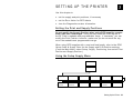
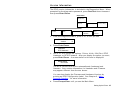
Using the Setup Supply Menu
M AIN MENU
S e tup
Supp ly
Supp ly Type
R ibbo n
S pee d
F eed Mod e
Back fe ed
P os ition in g
Dis pen se
Position
Back fe ed
Dis tance
Sepa ra to rs
Skip Inde x
Knife
Contro l
Erro r Ac tio n
Setting Up the Printer 3-1
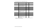
The following table lists the Supply Menu options.
Option
Supply Type
Choices
Default
Use for RFID
Aperture/Die Cut/Black Mark/
Die Cut
Die Cut
Continuous/Tag Edge Aperture
Ribbon
No/Yes/High Energy
Yes
Any
Speed
2.5/4.0/6.0/8.0/10.0/Default
Default
Any
Note: The printer pauses while
programming the RFID tag.
Feed Mode
Continuous/On-Demand
Continuous Any
Backfeed
Off/On/Extended
Off
Conditional*
Print Position
-450 to 450
0
Conditional*
Supply Position
-300 to 300
0
Conditional*
Margin Position
-99 to 99
0
Any
Cut Position
-300 to 300
0
0 only
Note: The knife is not currently
supported for use with RFID
supplies.
Dispense Position
50 to 200
65
Conditional*
Backfeed Distance 10 to 200
65
Conditional*
Separators
No/Yes/Long
No
Not recommended
Skip Index
No/Yes
No
Not recommended
Knife Control
-20 to 20
0
0 only
Error Action
Normal
Normal
Conditional*
Overstrike/Continue 1x to 5x
Note: If using “overstrike,” do not
use Peel Mode.
* Depends on the supply’s feed length. Refer to the RFID Setup Guide & Supply Chart for
the Supply and Print Position settings.
3-2 Multi-Protocol Application Notes
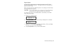
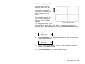
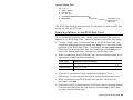
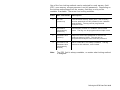
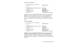
Setting the Supply Type
You can print on center
aperture, black mark, die
cut, continuous, or tag
edge aperture supplies.
You have to tell the printer
which supplies you are
using.
If using edge aperture tag
stock containing an RFID
antenna, select Tag Edge
Aperture.
Tag Edge Ap erture suppl y
To change the setting, from
the Main Menu, select Setup, then Supply. If password protection in
enabled, press Feed/Cut three times, then press Enter/Pause before you
see the Setup Menu options. Then, follow these steps.
1.
Press » or ¼ until you see
SUPPLY
Supply Type
2.
¼
Press Enter/Pause to set the supply type option. The current setting
is displayed, for example:
»
SUPPLY TYPE
Black Mark
¼
3.
Press » or ¼ to see the other options. After you display the option
you want, press Enter/Pause.
4.
Press Escape/Clear until you see the Main Menu.
Setting Up the Printer 3-3
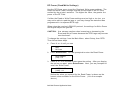
Setting the Error Action
The recovery action from an error condition is in the Setup, Supply Menu.
You can change how the printer responds to a bad label. The choices
include normal and overstrike/continue one to five consecutive bad
labels. The overstrike pattern is created to prevent someone from using
the label.
Selecting overstrike and continue 1x-5x sets the number of times the
printer prints an overstrike pattern on consecutively bad labels before
generating an error. The user must clear the error before operation can
continue.
Consider this scenario when the error action is set to
overstrike/continue 3x:
If the printer errors on the first label, an overstrike pattern is printed, but
the printer attempts to reprint the image up to three times. If the third
consecutive label also generates an error, an overstrike pattern is
printed; however, the printer stops and the error message is displayed.
The operator must resolve the error condition before printing continues.
In the above example, if the third label did NOT generate an error,
♦
the batch image is printed
♦
the consecutive error counter is reset
♦
the printer continues processing the batch.
Error Action Modes
The printer errors and the condition causing the
error is displayed. The error must be cleared
before operation can continue. An operator must
press Escape/Clear to clear the error and continue
printing. No overstrike pattern is printed.
Normal (default)
Overstrike/Continue
Overstrike/Continue
Overstrike/Continue
Overstrike/Continue
Overstrike/Continue
1x
2x
3x
4x
5x
The printer prints an overstrike pattern on one,
two, three, four, or five consecutive labels and
stops printing after the selected number of
overstrike patterns have been printed. An operator
must press Escape/Clear to clear the error and
continue printing.
3-4 Multi-Protocol Application Notes
Note:
The printer does not recalibrate (feed a blank label) after any
RFID error.
For more information about the error actions, see the following table.
Error Action
Standard
Peel
Verifier with
Peel
RFID with
Peel
Overstrike/Continue 1-5
No
No
No
Normal (no overstrike)
Yes
Yes
Yes
Note:
If using the Overstrike and Continue error mode, do not use peel
mode.
To change the setting, from the Main Menu, select Setup, then Supply.
Then follow these steps.
1.
Press
or
until you see
SUPPLY
Error Action
2.
Press Enter/Pause. The current setting is displayed, for example:
ERROR ACTION
Ostrk/Cont 1x
3.
Press
or
see the other options. After you display the option you
want, press Enter/Pause.
4.
Press Escape/Clear until you see the Main Menu.
Note:
Depending on the selected error action, you may or may not see
a label with the overstrike pattern.
Setting Up the Printer 3-5
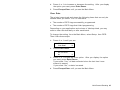
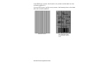
If an RFID error occurs, the format is not printed on the label, but the
overstrike pattern is.
If a non-RFID error (verifier error) occurs, the format prints on the label
with the overstrike pattern.
RFID Overstrike
3-6 Multi-Protocol Application Notes
Non- RFID Overstrike
printed from a verifier
error
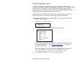
Version Information
The RFID version information is included in the Diagnostics Menu. When
prompted for the diagnostics password, press Feed/Cut three times and
then press Enter/Pause.
M AIN MENU
Diagn os tics
V e rs ion
Printe r
1.
Knife
1 284 Po rt
From the Diagnostics Menu, press
S e rv ice Diag
U se r D ia g
RFID
H a rdw a re
or
R F ID
F irmw a re
until you see
DIAGNOSTICS
Version
2.
Press Enter/Pause.
VERSION
RFID Hardware
3.
Use
or
to see all the options: Printer, Knife, 1284 Port, RFID
Hardware, or RFID Firmware. After you display the option you want,
press Enter/Pause. A screen similar to this one is displayed:
Model M9855
931110841
The RFID versions are for the antenna/board (hardware) and
firmware. Your version information for Hardware and Firmware
may appear different from the one shown.
You can also display the Firmware and Hardware Versions by
printing an RFID Configuration Label. See Chapter 2, “MultiProtocol Encoding,” for more information.
4.
Press Escape/Clear until you see the Main Menu.
Setting Up the Printer 3-7
Additional Font
An additional font, PaxarSymbols has been added to version 5.0 or
greater software. Currently, it contains one symbol, which is referenced
by using the capital letter A in the batch data.
♦
Use number 56 for the font identifier in the Text Field.
♦
Use a large enough point size (height and width magnification) to
display this graphical symbol.
Font Number
Example
T,2,10,V,250,50,0,56,30,30,B,L,0,0,0¦
Point Siz e (Height and
W idth Magnification )
Prints this symbol using the capital letter A in the batch data,
for example:
{B,1,N,1¦
2,"A"¦}
EPCglobal, Inc. and Electronic Product Code™ (EPC) are trademarks of Uniform Code Council, Inc.
3-8 Multi-Protocol Application Notes
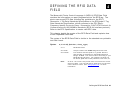
D E F I N I N G T H E R F I D D ATA
FIELD
4
The Monarch Printer Control Language II (MPCLII) RFID Data Field
contains the information you want programmed into the RFID tag. The
printer can accept EPC data following the guidelines in the EPC
Generation 1 Tag Data Standards Specification or the EPCglobal Tag
Data Standards Specification, which conforms to the EPC RadioFrequency Identity Protocols Class 1 Generation 2 UHF RFID Protocol for
Communications at 860-960MHz Standards (RFID Air Interface protocol).
Refer to the EPC Specification to create valid EPC data.
This chapter details the syntax of the RFID Data Field and explains how
to use Expanded Gen2 data.
The syntax of the RFID Data Field is similar to the standard non-printable
text field format.
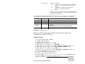
Syntax
X,field#,#ofchar,data_type¦
X1. X
RFID Data Field.
X2. field#
Unique number from 0-999 assigned to this field.
X3. #ofchar
This number must be equal to or greater than the
total number of characters in the RFID Data Field.
Range: 0-2710. The amount varies according to your
RFID data and protocol. For example, C1Gen2 can
be 96 bits, plus the access password, lock code, etc.
Note:
An error 715 occurs if the printer does not receive the correct
amount of data. You can pad data to make sure you have the
correct amount of bits. See “Using Option 30,” for more
information.
Defining the RFID Data Field 4-1
X4. data_type
Data type. Options:
0
ASCII Hex - default (ASCII representation
of Hex). Use characters A to F and 0 to 9.
1
ASCII
2
ASCII Binary (ASCII representation of
Binary). Use characters 0 or 1.
3
Hex
We recommend using ASCII Hex for compatibility with
multiple host applications. You should know the data
type your host provides.
For example, the letter A has a decimal value of 65 in the ASCII table. The hex (base
16) equivalent of decimal (base 10) is 41. Hex 41 in binary notation is 01000001.
Data Type
ASCII Hex
ASCII
ASCII
Binary
Character
41
A
01000001
Hex
~065
Example
MPCL Batch Data for a 96-bit RFID tag
"414141414141414141414141"
"AAAAAAAAAAAA"
"01000001010000010100000101000001010000010100000
101000001
0100000101000001010000010100000101000001"
"~065~065~065~065~065~065~065~065~065~065~065~065"
X,5,24,0¦
Defines an RFID Data Field (field #5) with exactly 24 ASCII Hex
characters for a 96-bit RFID tag.
Sample Format
{F,1,A,R,E,600,400,"RDCI"¦
L,V,500,115,90,85,3¦
L,V,298,245,90,102,3¦
C,568,8,0,2,2,2,B,L,0,0,"FROM:",0¦
C,568,125,0,2,2,2,B,L,0,0,"CARRIER:",0¦
C,387,8,0,2,1,1,B,L,0,0,"(420) SHIP TO POSTAL CODE",0¦
C,391,250,0,2,1,1,B,L,0,0,"APPOINTMENT NUMBER:",0¦
C,327,250,0,2,1,1,B,L,0,0,"ITEM:",0¦
C,190,8,0,2,1,1,B,L,0,0,"UPC SHIPPING CONTAINER CODE",0¦
T,1,15,V,529,220,0,2,2,2,B,L,0,0,0¦
B,3,13,V,311,28,8,4,50,8,L,0¦
B,4,14,V,17,60,50,5,130,8,L,0¦
X,5,24,0¦
RFID Data Field
T,6,20,V,415,270,0,50,15,15,B,L,0,2¦
Cop y Option
R,4,5,1,16,1,0¦
from field 5
…}
4-2 Multi-Protocol Application Notes
(RFID Data
Field) to field
6 (Text field)
Sample Batch Data
{B,1,N,1¦
1,"RFID TEST"¦
3,"1005678"¦
4,"67-90-32"¦
5,"3123456789ABCDEF12345678"¦
6,"ABCDEFG"¦
…}
RFID Data Field
Batch Data in
AS CII Hex
The RFID Data Field contains exactly 24 characters of data in ASCII Hex
format for a 96-bit RFID tag.
Applying Options to the RFID Data Field
All the normal field options (copy, merge, pad, increment, etc.) can be
applied to the RFID Data Field. However, certain restrictions may apply.
♦
To copy, merge, pad, or increment data in the RFID Data Field, the
copied/merged/padded/incremented data must be in the same format
specified in the RFID Data Field. For example, to copy data into the
RFID Data Field using ASCII Hex, the field being copied must be in
ASCII Hex format; otherwise, unexpected results may occur.
♦
When incrementing the RFID Data Field, see the following table for an
explanation of how the field increments.
Data Type
How the Field Increments
ASCII Hex
0 to F (0123456789ABCDEF), then back to 0
ASCII Binary
0 to 1 or 1 to 0
ASCII or Hex
next position in 0 to 255 range
♦
If Option 60 (Increment Field) contains the character “D” to
decrement, it is ignored and the field is instead incremented by one.
♦
When incrementing the RFID Data Field, the only valid value to
increment is by one.
♦
Use caution when incrementing an RFID field if data is coming directly
from your host because the field must be incremented in ASCII Hex
(or other specified data type).
Defining the RFID Data Field 4-3
Copy Option Example
{F,2,A,R,E,400,400,"ASCIIHEX"¦
X,2,24,0¦
T,1,50,V,10,10,0,1,1,1,B,L,0,0¦
R,4,2,1,16,1,2¦}
{B,2,N,2¦
1,"313233343536373831323334"¦
2,"313233343536373831323334"¦}
Cop y data from
RFID Data field
to text field
This example uses option 4 to copy data from the RFID Data Field and
displays the data in text field 1. Note the data type being used is ASCII
Hex, so the data in the RFID Data Field is in ASCII Hex format. This
example uses a 96-bit RFID tag.
Using Option 5 (Define Data Entry Sources)
Use this option to read pre-programmed data in the RFID chip embedded
within the supply. Using Option 5 stops the printer while reading each
label; regardless of the print speed. If using a batch quantity greater
than one, the data is read from each label.
Note:
Using Option 5 to read pre-programmed RFID data is supported
with the release of version 5.0 or greater printer’s software.
The EM4122 protocol requires Option 5 to read the preprogrammed data.
When reading data, make sure the maximum number of characters in the
field is equal to or greater than the number of characters being read. If
not, the data may be incomplete.
Use option 6 (Upload Field Data) with Option 5 to upload the data from
the RFID chip to a host.
4-4 Multi-Protocol Application Notes
Syntax
R,5,code¦
R1. R
Option Header.
R2. 5
Option 5.
R3. code
Input code for the data in the field. Options:
H
Host
K
Keypad
N
No user input for this field
R
RFID (read data from the RFID chip). This
is ignored on non-RFID printers.
Note:
Example
Option 5 re-images each label in the batch.
T,2,10,V,250,50,0,1,1,1,B,C,0,0,0¦
R,5,R¦
Reads the pre-programmed data from the RFID chip and saves that data
into the text field.
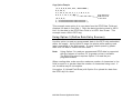
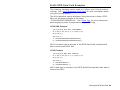
Using Option 6 (Upload Field Data)
You can upload data from any field using Option 6. When uploading
multiple fields of data, the data is comma separated.
Data is uploaded to the last port that received host data (serial, parallel,
USB, or Ethernet) at the end of the batch or label, depending on the other
options used as follows:
♦
When using a batch quantity of one without Option 5 or Option 60,
data is uploaded at the end of the batch.
♦
When using a batch quantity greater than one with an Option 5 and/or
Option 60, data is uploaded after each label.
Note:
Syntax
To upload data on a field that did not change, apply Option 60 to
that field.
R,6,device¦
R1. R
Option Header.
R2. 6
Option 6.
R3. device
Last port that received host data. Use H (host).
Defining the RFID Data Field 4-5
Example
T,2,10,V,250,50,0,1,1,1,B,C,0,0,0¦
R,6,H¦
Uploads the text field’s data to a file.
Example
B,3,12,F,50,50,1,2,60,7,L,0¦
R,6,H¦
R,60,I,0¦
Uploads the UPCA bar code field’s data to a file and uploads data for
each label in the batch.
Example
T,150,V,230,130,0,1,1,1,B,L,0,0¦
R,5,R¦
R,6,H¦
Reads the RFID data from the RFID chip embedded in the supply.
Uploads the data to the last-used port.
Example
{F,1,A,R,E,600,400,"RDCI"¦
…
X,5,24,0¦
T,6,20,V,415,270,0,50,15,15,B,L,0,2¦
R,4,5,1,16,1,0¦
R,6,H¦
…}
Copies data from field 5 (RFID Data Field) to field 6 (Text field). Uploads
the data to the last-used port.
Sample Upload Packet
Example
R,5,R¦
R,6,H¦
Returns the following in the upload packet:
313233343536373839303132
4-6 Multi-Protocol Application Notes
Pre-programmed data in the
RFID chip.
Example
B,3,12,F,50,50,1,2,60,7,L,0¦
R,6,H¦
Returns the following in the upload packet:
123456789012
Example
UPC A bar code data entered
from the batch.
R,5,R¦
R,6,H¦
B,3,12,F,50,50,1,2,60,7,L,0¦
R,6,H¦
Returns the following in the upload packet:
313233343536373839303132,123456789012
Pre-programmed data in
the RFID chip and the
UPC A bar code data
entered from the batch.
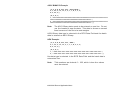
Defining the RFID Data Field 4-7
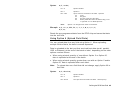
Using Option 30 (Pad Data)
You can add characters to one side of a field to "pad" the field. Padding
allows you to fill in the remaining spaces when the entered data does not
fill an entire field.
If a variable length field is not completely filled with batch data, this
option fills the remaining positions in the field with the character
designated by Option 30.
Syntax
R,30,L/R,"character"¦
R1. R
Option Header.
R2. 30
Option 30.
R3. L/R
Indicates type of padding
L Pad field on left side
R Pad field on right side
R4. "character"
Note:
Example
Pad character must be within the 0 - 255 decimal
range and enclosed inside quotation marks.
The pad character must be in the same format specified in the
RFID Data Field. See “Defining the RFID Data Field” for more
information.
R,30,L,"A"¦
Pads data with an "A" on the left side of the field.
Example
X,2,24,0¦
R,30,R,"0"¦
Pads the data in the RFID Data Field with a “0” on the right side of the
data. This example uses a 96-bit RFID tag.
4-8 Multi-Protocol Application Notes
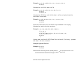
96-Bit RFID Data Field Examples
The following examples can be used for C1Gen1 and C1Gen2 (without
locking). See “Using Expanded Gen2 Data” for more information about
using the locking feature.
The 96-bit data that can be displayed using the printer’s Setup, RFID
Menu for all these examples is the same:
“313233343536373839303132.” See “Read Tag” for more information
about displaying what is programmed into an RFID tag.
ASCII HEX Example
{F,2,A,R,E,400,400,"ASCIIHEX"¦
T,1,50,V,10,10,0,1,1,1,B,L,0,0¦
X,2,24,0¦}
{B,2,N,1¦
1,"313233343536373839303132"¦
2,"313233343536373839303132"¦}
ASCII Hex data type is selected in the RFID Data Field and the batch
data is entered as ASCII Hex.
ASCII Example
{F,2,A,R,E,400,400,"ASCII"¦
T,1,50,V,10,10,0,1,1,1,B,L,0,0¦
X,2,12,1¦}
{B,2,N,1¦
1,"123456789012"¦
2,"123456789012"¦}
ASCII data type is selected in the RFID Data Field and the batch data is
entered as ASCII.
Defining the RFID Data Field 4-9
ASCII BINARY Example
{F,2,A,R,E,400,400,"ASCIIBIN"¦
T,1,96,V,10,10,0,2,1,1,B,L,0,0¦
X,2,96,2¦}
{B,2,N,1¦
1,"0011000100110010001100110011010000110101001101100011011
10011100000111001001100000011000100110010"¦
2,"0011000100110010001100110011010000110101001101100011011
10011100000111001001100000011000100110010"¦}
Note:
The ASCII Binary data needs to be entered on one line. Do not
use line breaks to wrap the data. This data is shown on several
lines because of the font size and margins.
ASCII Binary data type is selected in the RFID Data Field and the batch
data is entered as ASCII Binary.
HEX Example
{F,2,A,R,E,400,400,"HEX"¦
T,1,50,V,10,10,0,1,1,1,B,L,0,0¦
X,2,12,3¦}
{B,2,N,1¦
1,"~049~050~051~052~053~054~055~056~057~048~049~050"¦
2,"~049~050~051~052~053~054~055~056~057~048~049~050"¦}
Hex data type is selected in the RFID Data Field and the batch data is
entered as Hex.
Note:
Tilde numbers are decimal 0 – 255, which is how Hex values
must be entered.
4-10 Multi-Protocol Application Notes
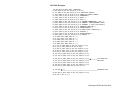
SSCC96 Example
{F,45,A,R,E,600,400,"SSCC96"¦
C,45,220,0,50,10,10,B,L,0,2,"®"¦
C,75,385,0,50,40,30,B,L,0,2,"Monarch RFID"¦
C,110,385,0,50,6,6,B,L,0,2,"SHIP TO RFID USER"¦
C,110,150,0,50,6,6,B,L,0,2,"CARRIER"¦
C,150,150,0,50,9,9,B,L,0,2,"PRO:"¦
C,165,150,0,50,9,9,B,L,0,2,"B/L:"¦
C,200,380,0,50,18,15,B,L,0,2,"PAXAR AMERICAS, Inc."¦
C,235,380,0,50,14,12,B,L,0,2,"EMAIL: [email protected]"¦
C,255,380,0,50,14,12,B,L,0,2,"PHONE: 1 800 543-6650"¦
C,275,345,0,50,6,6,B,L,0,2,"VENDOR STK NO:"¦
C,275,110,0,50,6,6,B,L,0,2,"PACK/UNITS:"¦
C,360,330,0,50,10,10,B,L,0,2,"EPC Pure Identity:"¦
C,275,190,0,50,6,6,B,L,0,2,"COLOR:"¦
C,315,110,0,50,6,6,B,L,0,2,"SIZE/STYLE:"¦
C,415,390,0,50,12,12,B,L,0,2,"EPC#:"¦
L,S,098,005,098,395,6,""¦
L,S,170,005,170,395,6,""¦
L,S,098,155,170,155,6,""¦
L,S,260,005,260,395,6,""¦
L,S,390,005,390,395,6,""¦
T,1,15,V,130,335,0,50,13,12,B,L,0,2¦
B,2,15,V,165,365,8,4,25,0,L,2¦
T,3,20,V,130,150,0,50,13,12,B,L,0,2¦
T,4,20,V,150,110,0,50,10,12,B,L,0,2¦
T,5,20,V,165,110,0,50,10,12,B,L,0,2¦
T,12,10,V,295,370,0,50,15,18,B,L,0,2¦
T,13,10,V,295,110,0,50,15,18,B,L,0,2¦
T,14,50,V,380,385,0,50,12,11,B,L,0,2¦
T,15,10,V,295,200,0,50,15,18,B,L,0,2¦
T,16,10,V,335,155,0,50,15,18,B,L,0,2¦
T,18,30,V,550,330,0,50,15,18,B,L,0,2¦
B,17,20,V,530,340,50,6,110,0,L,2¦
Text Field w ith
EPC Data
X,19,24¦
RFID Data Field
T,20,40,V,415,330,0,50,12,13,B,L,0,2¦
R,4,19,1,40,1,1¦}
Defining the RFID Data Field 4-11
Batch Data
{B,45,N,1¦
1,"VENDOR USA"¦
2,"42060512"¦
3,"PAXAR AMERICAS"¦
4,"0987764356"¦
5,"0020545640"¦
12,"0075687332"¦
13,"3600"¦
14,"urn:epc:tag:sscc-96:1.0028028.0000001235"¦
15,"RED"¦
16,"48~"/TOUGH"¦
17,"009280287586887"¦
18,"0 09 28028 75688 7"¦
19,"313401B5F0000004D3000000"¦
20,"0"¦}
Text Field Batch
Data
RFID Field Batch
Data
SGTIN 96 Example
{F,46,A,R,E,600,400,"SGTIN96"¦
C,45,220,0,50,10,10,B,L,0,2,"®"¦
C,75,385,0,50,40,30,B,L,0,2,"Monarch RFID"¦
C,110,385,0,50,6,6,B,L,0,2,"SHIP TO RFID USER"¦
C,110,150,0,50,6,6,B,L,0,2,"CARRIER"¦
C,150,150,0,50,9,9,B,L,0,2,"PRO:"¦
C,165,150,0,50,9,9,B,L,0,2,"B/L:"¦
C,200,380,0,50,18,15,B,L,0,2,"PAXAR AMERICAS, Inc."¦
C,235,380,0,50,14,12,B,L,0,2,"EMAIL: [email protected]"¦
C,255,380,0,50,14,12,B,L,0,2,"PHONE: 1 800 543-6650"¦
C,275,345,0,50,6,6,B,L,0,2,"VENDOR STK NO:"¦
C,275,110,0,50,6,6,B,L,0,2,"PACK/UNITS:"¦
C,360,330,0,50,10,10,B,L,0,2,"EPC Pure Identity:"¦
C,275,190,0,50,6,6,B,L,0,2,"COLOR:"¦
C,315,110,0,50,6,6,B,L,0,2,"SIZE/STYLE:"¦
C,415,390,0,50,12,12,B,L,0,2,"EPC#:"¦
L,S,098,005,098,395,6,""¦
L,S,170,005,170,395,6,""¦
L,S,098,155,170,155,6,""¦
L,S,260,005,260,395,6,""¦
L,S,390,005,390,395,6,""¦
T,1,15,V,130,335,0,50,13,12,B,L,0,2¦
B,2,15,V,165,365,8,4,25,0,L,2¦
4-12 Multi-Protocol Application Notes
T,3,20,V,130,150,0,50,13,12,B,L,0,2¦
T,4,20,V,150,110,0,50,10,12,B,L,0,2¦
T,5,20,V,165,110,0,50,10,12,B,L,0,2¦
T,12,10,V,295,370,0,50,15,18,B,L,0,2¦
T,13,10,V,295,110,0,50,15,18,B,L,0,2¦
T,14,50,V,380,385,0,50,12,11,B,L,0,2¦
T,15,10,V,295,200,0,50,15,18,B,L,0,2¦
T,16,10,V,335,155,0,50,15,18,B,L,0,2¦
T,18,30,V,550,330,0,50,15,18,B,L,0,2¦
B,17,20,V,530,340,50,6,110,0,L,2¦
Text Field w ith
EPC Data
X,19,24¦
RFID Data Field
T,20,40,V,415,330,0,50,12,13,B,L,0,2¦
R,4,19,1,40,1,1¦}
Batch Data
{B,46,N,1¦
1,"VENDOR USA"¦
2,"42060512"¦
3,"PAXAR AMERICAS"¦
4,"0987764356"¦
5,"0020545640"¦
12,"0075687332"¦
13,"3600"¦
14,"urn:epc:tag:sgtin-96:1.0028028.001234.2"¦
15,"RED"¦
Text Field
16,"48~"/TOUGH"¦
Data
17,"009280287586887"¦
18,"0 09 28028 75688 7"¦
19,"303401B5F001348000000002"¦
20,"0"¦}
Batch
RFID Field Batch
Data
Defining the RFID Data Field 4-13
Using Expanded Gen2 Data
With version 5.0 or greater software, we support Expanded C1Gen2 data,
which is composed of five different fields:
♦
EPC Data (64 or 96-bit)
♦
Kill Password
♦
User Memory
♦
Lock Code
♦
Access Password
The printer also accepts EPC data following the guidelines in the
EPCglobal Tag Data Standards Specification, which conforms to the
EPC Radio-Frequency Identity Protocols Class 1 Generation 2 UHF RFID
Protocol for Communications at 860-960MHz Standards (RFID Air
Interface protocol). Refer to the EPC Specification to create valid EPC
data.
Many different RFID supplies (tags) are available and the amount of
programmable user memory varies with the chip embedded in the tag.
Depending on your tag type, all memory fields may not be available.
Refer to the RFID Setup Guide & Supply Chart for details about the
available user memory for each chip.
Note:
Incrementing an Expanded C1Gen2 RFID Data Field is not
supported.
Use the access password to control when new data can be written to a
field. The kill password sets a tag up to be inoperable. The lock code
contains the locking method.
4-14 Multi-Protocol Application Notes
One of the four locking methods can be selected for each memory field
(EPC, user memory, access password, and kill password). Depending on
the locking method specified, the memory field may or may not be
readable or writable. There are four locking methods.
Value
EPC Lock Name
Description
0
No lock
(unsecure)
The selected memory fields (EPC, user memory,
access password and kill password) are readable
and writable. The tag can be programmed
multiple times.
1
Permalock
(permanently
unsecure)
Permanently locked in a readable and writable
state. The tag can be programmed multiple times.
2
Password lock
(secure)
Requires the access password to rewrite the
selected memory fields. The tag can be
programmed multiple times with the password.
3
Permalock and
Password lock
(permanently
locked)
Never rewritable, but always readable. The tag
can never be rewritten, once locked.
Note:
The EPC field is always readable, no matter what locking method
is assigned.
Defining the RFID Data Field 4-15
The following table describes the locking method for each memory field.
EPC Memory
Description
0
EPC is readable and writable.
1
EPC is permanently writable (can never be locked).
2
EPC is only writable with password, but is readable.
3
EPC is never rewritable, but is readable.
User Memory
Description
0
User memory is readable and writable.
1
User memory is permanently writable (can never be
locked), but is readable.
2
User memory is only writable with password, but is
readable.
3
User memory is never rewritable, but is readable.
Access Password
Description
0
Access password is readable and writable.
1
Access password is permanently writable (can never
be locked).
2
Access password is never readable.
3
Access password is never readable or rewritable.
Kill Password
Description
0
Kill password is readable and writable.
1
Kill password is permanently writable (never locked), but
is readable.
2
Kill password is only writable with password.
3
Kill password is never readable or rewritable.
4-16 Multi-Protocol Application Notes
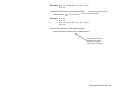
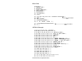
To use the Expanded C1Gen2 data, you need to modify the RFID Field’s batch data.
Syntax
field#,"EPC_data~028"¦
C,"User_Mem~028"¦
C,"~028"¦
C,"Acs_Pwd~028"¦
C,"Kill_Pwd~028"¦
C,"Lock_Code"¦
field#
Identifies the RFID Data Field number for the
following data. Range: 1 - 999.
"EPC_data~028"
EPC data. Enclose in quotation marks. To
create EPC data, follow the guidelines in the
EPC Global Generation 1 Tag Data Standards
Specification. The data must be in the same
format (ASCII Hex, ASCII, etc.) specified in the
RFID Data Field (data_type).
The printer can program 96-bits of data
(24 ASCII Hex characters). The data must end
with the ASCII field separator (decimal 028).
C,"User_Mem~028"
User Memory. Enclose in quotation marks. The
amount of programmable user memory varies
with the tag types. Refer to the RFID Setup
Guide & Supply Chart for details about the
available user memory for each chip.
The printer can program up to 304-bits of data
(76 ASCII Hex characters). The data must be
ASCII Hex characters and end with the ASCII
field separator (decimal 028).
Note:
Do not enter more characters than the user memory space
available. For example, if your tag has 96-bit user memory
available, you cannot enter more than 96-bits of data for
this field. However, you can enter less than 96-bit without
an error.
C,"~028"
Identifies information to be appended. Reserved
for future use. Only include the field separator
(decimal 028) in this field.
C,"Acs_Pwd~028"
Access Password. This must be 8 ASCII Hex
characters. No password is assigned if this field
is left blank. The data must end with the ASCII
field separator (decimal 028).
C,"Kill_Pwd~028"
Kill Password. This must be 8 ASCII Hex
characters. No password is assigned if this field
is left blank. The data must end with the ASCII
field separator (decimal 028).
Defining the RFID Data Field 4-17
C,"Lock_Code"
Note:
Five-digit locking method for each field in this
order:
EPC Data, User Memory, Reserved, Access
password, and Kill password. Use 0 for the
reserved field.
Locking options:
0
No Lock
1
Permalock
2
Password lock
3
Permalock & password lock
Use only one locking method per field.
The printer is not capable of unlocking a field. Depending
on the locking method used for each field, the EPC data
may be programmable by sending the access password
with the batch data. See the following examples.
Permalock Example
{F,1,A,R,E,400,400,"PERMLOCK"¦
X,1,100,0¦}
RFID Data Field
{B,1,N,1¦
1,"313233343536373831323334~028"¦
C,"ABCDEF~028"¦
C,"~028"¦
C,"73737373~028"¦
C,"CAD01234~028"¦
C,"11001"¦}
EPC Data
User Memory
Reserved
Access Password
Kill Password
Lock Method for each field:
Parameter
Description
Data
One
EPC
1
Two
User Memory
1
Three
Reserved
0
Four
Access Password
0
Five
Kill Password
1
The EPC data is 313233343536373831323334, the user memory data is
ABCDEF, the access password is 73737373, and the kill password is
CAD01234. Selects permalock (1) as the locking method for the EPC,
user memory, and kill field. Selects no lock (0) for the access password
field. The EPC, user memory, and kill fields are permanently
readable/writable.
4-18 Multi-Protocol Application Notes
Password Lock Example
{F,1,A,R,E,400,400,"PWDLOCK"¦
X,1,100,0¦}
RFID Data Field
{B,1,N,1¦
1,"313233343536373831323334~028"¦
C,"ABCDEF ~028"¦
C,"~028"¦
C,"73737373~028"¦
C,"CAD01234~028"¦
C,"22022"¦}
EPC Data
User Memory
Reserved
Access Password
Kill Password
Lock Method for each field
The EPC data is 313233343536373831323334, the user memory data is
ABCDEF, the access password is 73737373, and the kill password is
CAD01234. Selects password lock (2) as the locking method for the
EPC, user memory, access, and kill fields. To change the EPC, user
memory, or kill fields, the access password must be sent with the batch
data.
Both Lock Example
{F,1,A,R,E,400,400,"BOTHLOCK"¦
X,1,100,0¦}
RFID Data Field
{B,1,N,1¦
1,"313233343536373831323334~028"¦
C,"ABCDEF ~028"¦
C,"~028"¦
C,"73737373~028"¦
C,"CAD01234~028"¦
C,"33033"¦}
EPC Data
User Memory
Reserved
Access Password
Kill Password
Lock Method for each field
The EPC data is 313233343536373831323334, the user memory data is
ABCDEF, the access password is 73737373, and the kill password is
CAD01234. Selects permalock and password lock (3) as the locking
method for the EPC, user memory, access, and kill fields, which means
these fields are never rewritable. The EPC data can only be programmed
ONE time.
Defining the RFID Data Field 4-19
4-20 Multi-Protocol Application Notes
5
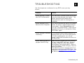
TROUBLESHOOTING
Use this chapter as a reference for any RFID errors you may
receive.
Problem
Action
Printer displays “Please
Wait RFID Initialization.”
You sent an RFID batch before the printer
communicated with the interrogator. The
printer prints the RFID batch once
communication with the interrogator is
complete.
Printer displays “RFID
Detection Not Complete.”
You tried to access the Setup, RFID Menu
before the printer communicated with the
interrogator. Press Escape/Clear until
you see “Print Mode Ready.” Wait several
seconds and then try to access the Setup,
RFID Menu again.
Printer displays “Monarch
Initializing.”
This message should flash briefly on the
display when you turn on the RFID printer.
If it does not disappear, turn off the
printer; wait fifteen seconds and then turn
on the printer.
Printer does not read or
program the RFID tag.
Make sure the following are set correctly
for your inlay (RFID tag) type: Protocol
(C1Gen1, EM4122, etc.), Read Power,
Write Power, and Signal Adjust. Refer to
your RFID Setup Guide & Supply Chart for
more information.
The EM4122 protocol requires option 5 to
read the pre-programmed RFID data. See
Chapter 4, “Defining the RFID Data Field”
for more information.
Troubleshooting 5-1
RFID Errors
052
Data type in the RFID Data Field must be 0, 1, 2, or 3. See “Defining the RFID
Data Field” for more information.
226
Rule Record Line xx. Upload device must be H (Host) for Option 6.
715
Invalid data length/data mismatch. The data in the RFID Data Field has an
incorrect data length or there is a data type mismatch between selected data type
and actual data entered. See “Defining the RFID Data Field” for more information
on the data length and for selecting the appropriate data type for the data being
entered. This error also occurs when there is an error in the Expanded C1Gen2
fields. Check with your System Administrator about your format.
740
Command, hardware, inventory, or memory allocation error. There may be an
RFID hardware or memory allocation error.
741
RFID tag missing. Tag not found in RF Field. The RFID tag was not found in the
RF Field (area inside the printer where RFID tag is programmed.) Check supply
loading. If you made supply or print position settings, make sure the RFID tag was
not moved out of the programmable range. See “About RFID Supplies,” in Chapter 2
for more information.
742
Tag erase failed. The RFID tag was found in the RF Field, but could not be erased.
Increase the number of retries. If this error occurs consecutively, increase or
decrease the RFID power setting by one. If the RFID power is set too low, you may
affect the data programmed in adjacent labels.
743
Program tag failed. The RFID tag was found in the RF Field, but could not be
programmed. Increase the number of retries. If this error occurs consecutively,
increase or decrease the RFID power setting by one. If the RFID power is set too
low, you may affect the data programmed in adjacent labels.
744
Tag locked fail. The RFID tag is unable to be programmed, because it is already
locked. This is considered a bad RFID tag. See “Error Action” on how to handle the
error.
746
Lock tag fail. The RFID tag has not been locked to prevent reprogramming. This
is considered a bad RFID tag. See “Error Action” on how to handle the error.
747
Time out failure. Any RFID command (read, program, etc.) has failed to complete
in the maximum amount of allowed time.
748
Invalid data length/data mismatch from RFID interrogator module. The RFID
interrogator module found a problem with the data received from the printer.
749
RFID Verify Fail. The RFID verification process failed after writing (programming)
tag. This is considered a bad RFID tag. See “Error Action” on how to handle the
error.
The printer does not recalibrate (feed a blank label) after any RFID error.
Call Technical Support for any message not listed.
5-2 Multi-Protocol Application Notes
INDEX
A
access password ..... 4-14, 4-17
ASCII
data type ....................... 4-2
sample .......................... 4-9
ASCII binary
sample ........................ 4-10
ASCII Binary
data type ....................... 4-2
ASCII hex
sample .......................... 4-9
ASCII Hex
data type ....................... 4-2
C
Class 0+
protocol .................. 2-1,
Class 1 Gen 1
protocol .................. 2-1,
Class 1 Gen 1 EPC
protocol .................. 2-1,
Class 1 Gen 2
protocol .................. 2-1,
clear data .................. 2-1,
copy
option ............................
2-9
2-9
2-9
2-9
2-7
4-3
D
data
EPC ................................ 2-9
data field
RFID ............................. 4-1
data type
ASCII ............................ 4-2
ASCII Binary .................. 4-2
ASCII Hex ...................... 4-2
Hex ............................... 4-2
defaults
read tag ......................... 2-1
RF power ....................... 2-1
setup menu .................... 2-1
signal adjust ................... 2-1
write retries .................... 2-1
define
RFID data field ............... 4-1
E
edge aperture
supply ............................ 3-3
EM4122
protocol2-1, 2-9, 4-4, 4-5, 5-1
EPC
symbol ........................... 3-8
terms ............................. 1-3
EPC data........................... 2-9
lock .................... 4-14, 4-17
read ............................... 2-3
error
printer ............................ 5-1
programming tag ...... 5-1, 5-2
recovery action ............... 3-4
RFID message ......... 5-1, 5-2
error action........................ 3-4
normal (no overstrike) ..... 3-4
overstrike ....................... 3-4
H
hex
sample ......................... 4-10
Hex
data type ........................ 4-2
Index i
I
increment
option ............................ 4-3
inlay
terms ............................. 1-3
interrogator
terms ............................. 1-3
K
kill password ........... 4-14, 4-17
L
label
overstrike....................... 3-4
overstrike sample ........... 3-6
RFID configuration.......... 2-8
lock
EPC data ............. 4-14, 4-17
RFID tag .............. 4-18, 4-19
RFID tags ............ 4-14, 4-17
lock code ................ 4-14, 4-17
M
memory
user............ 4-14, 4-16, 4-17
N
normal (no overstrike)
error action .................... 3-4
O
option
30 (pad data) .......... 4-3, 4-8
4 (copy) ......................... 4-3
5 (data entry sources) ..... 4-4
6 (upload data) ............... 4-5
60 (increment) ................ 4-3
read RFID data ............... 4-4
overstrike
bad label........................ 3-4
error action .................... 3-4
sample........................... 3-6
ii Multi-Protocol Application Notes
P
pad data
option ..................... 4-3, 4-8
password
access ................ 4-14, 4-17
kill ...................... 4-14, 4-17
password lock
sample ......................... 4-19
permalock
sample ......................... 4-18
permalock and password lock
sample ......................... 4-19
print configuration label ...... 2-1
print position
setting............................ 3-1
printer
error .............................. 5-1
error recovery ................. 3-4
programming tag
error ....................... 5-1, 5-2
protocol
Class 0+.................. 2-1, 2-9
Class 1 Gen 1 .......... 2-1, 2-9
Class 1 Gen 1 EPC .. 2-1, 2-9
Class 1 Gen 2 .......... 2-1, 2-9
EM41222-1, 2-9, 4-4, 4-5, 5-1
R
read
EPC data........................ 2-3
tag ................................. 2-3
read power
setting............................ 2-6
read tag
defaults .......................... 2-1
recovery action
error .............................. 3-4
RF field
terms ............................. 1-3
RF power
defaults .......................... 2-1
setting............................ 2-6
RFID
configuration label .......... 2-8
data field ....................... 4-1
supply ........................... 2-1
RFID data field
define ............................ 4-1
sample .......................... 4-2
terms ............................. 1-3
RFID power
terms ............................. 1-3
RFID reader
terms ............................. 1-3
RFID tags
lock ..................... 4-14, 4-17
terms ............................. 1-3
S
sample
ASCII ............................ 4-9
ASCII binary ................ 4-10
ASCII hex ...................... 4-9
hex .............................. 4-10
overstrike label .............. 3-6
password lock .............. 4-19
permalock .................... 4-18
permalock and password lock4-19
RFID data field ............... 4-2
SGTIN 96..................... 4-12
SSCC96....................... 4-11
settings
print position .................. 3-1
read power..................... 2-6
RF power ....................... 2-6
signal adjust .................. 2-5
supply position ............... 3-1
write power .................... 2-6
write retries ................... 2-4
setup menu
defaults ......................... 2-1
SGTIN 96
sample ........................ 4-12
signal adjust
defaults .......................... 2-1
setting ........................... 2-5
SSCC96
sample ......................... 4-11
supply
edge aperture ................. 3-3
options ........................... 3-3
position,setting ............... 3-1
RFID .............................. 2-1
tag edge aperture ........... 3-3
symbol
EPC ............................... 3-8
T
terms
EPC ............................... 1-3
inlay .............................. 1-3
interrogator .................... 1-3
RF field .......................... 1-3
RFID data field ............... 1-3
RFID power .................... 1-3
RFID reader ................... 1-3
RFID tags ....................... 1-3
transponder .................... 1-4
transponder
Class 1 .......................... 1-2
terms ............................. 1-4
type ............................... 1-2
type
transponder .................... 1-2
U
upload
RFID data ...................... 4-5
user memory... 4-14, 4-16, 4-17
W
write power
setting ........................... 2-6
write retries
defaults .......................... 2-1
setting ........................... 2-4
Index iii
iv Multi-Protocol Application Notes
Visit www.monarch.com for sales, service,
supplies, information, and telephone numbers
for our locations throughout the world.
TOLL FREE:
1-800-543-6650 (In the U.S.A.)
1-800-363-7525 (In Canada)