1
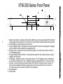
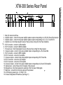
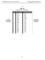
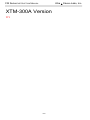
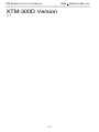
XTM-300 SERIES
Crossover Module
181 Bonetti Drive
San Luis Obispo, CA 93401
ph: 805-549-0161
fax: 805-549-0163
e-mail:[email protected]
CM Series INSTRUCTION MANUAL
Ultra Stereo Labs, Inc.
One Year Limited Warranty
USL, Inc. warrants that each product manufactured by it will be
free from defects in material and workmanship under normal usage
for a period of one (1) year after its purchase new from an authorized
dealer. Our obligation under this warranty is limited to repairing
or replacing any product or component which we are satisfied does
not conform with the foregoing warranty and which is returned to
our factory, freight paid, or serviced by one of our authorized
contractors. The forgoing warranty is exclusive and in lieu of all
other warranties, whether expressed or implied. Such warranty
shall not apply to any product or component (A) repaired or altered
by anyone other than USL, Inc. or an authorized service contractor;
(B) tampered with or altered in any way or subjected to misuse,
negligence or accident or (C) which has been improperly connected
installed or adjusted other than in accordance with USL, Inc.’s
instruction.
-1-
CM Series INSTRUCTION MANUAL
Ultra Stereo Labs, Inc.
Table of Contents
Introduction .........................................................3
Front Panel Description........................................5
Rear Panel Description.........................................6
Installation............................................................7
HD-15 Wiring Diagram........................................8
XTM-300A...............................................................9
Crossover Setup...................................................10
XTM-300D...........................................................11
Specifications......................................................12
Please record the following information for your records:
Model:
Date of Purchase:
Purchased from:
Serial Number:
-2-
CM Series INSTRUCTION MANUAL
Ultra Stereo Labs, Inc.
Introduction
Please read this entire manual before commencing your
installation.
The Ultra*Stereo XTD-680 is a digital crossover card for use with a CM
series Crossover Monitor Chassis and may provide either three channels
(Left, Center, Right) or, with the addition of a piggyback board, two additional
channels (Left Center, Right Center) of Biamp or Triamp crossover capability.
Subwoofer control is also provided. The card is configured for individual
requirements by an easy to use Graphical User Interface that runs on a
laptop computer communicating via a USB cable. A library of existing
speaker types is provided or each of the features may be configured
manually. Cinema Profile information may be entered for future reference.
Additionally, the XTD-680 is designed to interface with Ultra Stereo's JSD80 for complete system equalization.
As a result, only the Bypass features need to be configured on the XTD680 card itself. A DIP switch selects the type of Bypass crossover
(Triamp/Biamp/Biamp Frequency) and three potentiometers set the Bypass
crossover levels. In use, there is only a two position switch for selecting
"Normal" or "Bypass" operation.
TOOLS REQUIRED
Small, standard
screwdriver
Trimpot
adjustment
tool
No. 2 Phillips
screwdriver
-3-
Wire
Strippers
CM Series INSTRUCTION MANUAL
Ultra Stereo Labs, Inc.
You will need to supply the following materials:
• Shielded audio cable for connecting the CM Series to the
cinema processor and power amplifier outputs.
• Four 10-32 x 1/2" screws to mount the CM Series in the audio
equipment rack.
FEATURES
???
-4-
-5-
Ultra
Stereo Labs, Inc.
1. Channel select buttons - pressing a Channel Select Button causes the corresponding LED to illuminate
and the signal from that channel to be monitored. Any combination of eight channels can be selected.
2. Internal Digital or Analog Crossover Access Cover.
3. Crossover Bypass Switch - Switching this will cause the internal crossover to be bypassed or engaged
and the condition will be indicated by its appropriate LED.
4. Volume Control - controls the volume of the internal speaker. The volume control has no effect on
the VU Bargraph display.
5. Processor/Amplifier Selector Switch - selects either the inputs from the cinema processor or power
amplifiers for monitoring.
6. VU Bargraph - displays the level of the selected channels. The VU Bargraph may be calibrated by
the rear panel trim adjustment. The VU Bargraph operates independently of the volume control (4).
7. Test Jack - permits monitoring of the audio output of the CM-680. Inserting a mono or stereo 1/4”
phone plug here disables the internal speaker and routes the audio output to the Test Jack. Do
not connect any device here with less than 8 Ohms impedance.
8. Internal Speaker
9. Power Switch
CM Series INSTRUCTION MANUAL
XTM-300 Series Front Panel
-6-
Ultra
Stereo Labs, Inc.
1. Main AC connector with fuse.
2. Amplifier outputs - connect to the power amplifier speaker outputs corresponding to Ls, Rs, Bsl, Bsr and Sw channels.
3. Amplifier outputs - connect to the power amplifier speaker outputs corresponding to Lh, Ll, Ch, Cl and Rh, Rl.
4. Amplifier level - this trimpot adjusts the level of the input lines coming from the Power Amplifiers.
5. HD-15 connector - connect to Ls/Rs amplifier.
6. HD-15 connector - connect to Bsl/Bsr amplifier.
7. Processor level - this trimpot adjusts the level of the input lines coming from the processor.
8. Crossover outputs - connect to the power amplifier inputs corresponding to Ls, Rs, Bsl and Bsr.
9. HD-15 connector - connect to Rl/Rh amplifier.
10. HD-15 connector - connect to Sw amplifier.
11. Crossover outputs - connect to the power amplifier inputs corresponding to Rl, Rh and Sw.
12. HD-15 connector - connect to Ll/Lh amplifier.
13. HD-15 connector - connect to Cl/Ch amplifier.
14. Crossover outputs - connect to the power amplifier inputs corresponding to Ll/Lh and Cl/Ch amplifier.
15. Optional input - connect these to the EX outputs of the processor
16. Bargraph level - this trimpot adjusts the sensitivity of the front panel VU Bargraph.
17. Main input - connect this to the main outputs of the processor.
18. AC Emergency power input - 12-16VAC, 0.5A
19. Channel configuration DIP switches. (See Page 11)
CM Series INSTRUCTION MANUAL
XTM-300 Series Rear Panel
CM Series INSTRUCTION MANUAL
Ultra
Stereo Labs, Inc.
Installation
Mount the XTM-300 Series
The ideal place for the XTM-300 Series Monitor is in the sound rack
or projector console between the stereo processor and power
amplifiers. DB25 connectors are available on the back plane to make
installation quick and easy. Alternatively, terminal blocks allow the use
of stripped and tinned wire. They are pluggable for easy service and
trouble shooting.
XTM-300 Hookup
1. Power: Connect the unit to the AC power outlet using the standard
IEC cable provided. Any power source from 100-250VAC, 50-60 Hz
will be sufficient.
2. ???
-7-
CM Series INSTRUCTION MANUAL
Ultra
Stereo Labs, Inc.
???
DB-25
Connector Pinout
Main
Processor
Outputs
Pin #
Function
Function
1
2
3
4
5
6
7
8
9
10
11
12
13
14
15
16
17
18
19
20
21
22
23
24
25
GND
L+
N/C
GND
C+
N/C
GND
R+
GND
LS RS SW GND
LN/C
N/C
CN/C
N/C
RN/C
GND
LS +
RS +
SW +
N/C
N/C
Bsl N/C
Ch +
Bsr GND
Rh +
N/C
Ls Rs Lh N/C
N/C
N/C
Bsl +
Ch N/C
Bsr +
Rh N/C
N/C
Ls +
Rs +
Lh +
-8-
Optional
Processor
Outputs
CM Series INSTRUCTION MANUAL
Ultra
XTM-300A Version
???
-9-
Stereo Labs, Inc.
CM Series INSTRUCTION MANUAL
Ultra
Stereo Labs, Inc.
Crossover Bypass Setup
This unit can be equipped with either the XTD-680D, a fully digital biamp/triamp
crossover card, the XTA-680EA, an analog crossover card or the XTB-680B,
a bypass card when no crossover functions are desired with the monitor. The
XTD-680D and the XTA-680B are discussed in detail in their own instruction
manuals.
1. Bypass Card XTB-680B: When using external crossovers, the CM Series
must be equipped with a bypass card in the crossover slot.
For external crossovers or crossovers built into amplifiers:
Turn biamp switch “ON”, triamp “OFF”.
Feed the channel “A” output of the
Ll/Lh, Cl/Ch, and Rl/Rh HD15
connectors to the appropriate amps.
BIAMP
ON
Feed the Ll, Cl and Rl terminals on
the Phoenix connectors to the
appropriate amps.
To USE CP-650 internal crossover with CM Series Monitors.
For biamp operation, turn biamp
switch to “ON”and triamp switch “OFF”.
- 10 -
OFF
TRIAMP
OR
CM Series INSTRUCTION MANUAL
Ultra
XTM-300D Version
???
- 11 -
Stereo Labs, Inc.
CM Series INSTRUCTION MANUAL
Ultra
Stereo Labs, Inc.
Specifications
???
Construction
??? The CM Series Monitor is constructed of steel to minimize
hum pickup and noise radiation. The overall size of the unit is
3.5" x 19" x 9.625". The CM Series is designed to mount in a standard
rack frame or cabinet.
CM-680
??? Weight: 10 lbs. 2 oz.
4.63kg)
Shipping weight: 16 lbs. (7.26kg)
Shipping Size: 22” x 22” x 6” (558.8 x 558.8 x 152.4 mm)
- 12 -