1
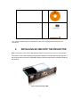
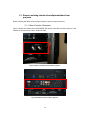
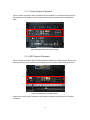
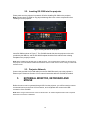
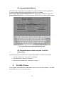
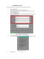
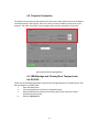
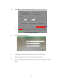
INSTALLATION MANUAL FOR SX-3000 STANDALONE INTEGRATED MEDIA BLOCK™ WITH PSD-3000-P PORTABLE STORAGE DEVICE SMS version 9.0 July 29, 2013 Table of Contents 1. INTRODUCTION ..................................................................................................... 6 1.1. Equipment List......................................................................................................... 7 2. INSTALLING SX-3000 INTO THE PROJECTOR ..................................................... 9 2.1. Remove existing interface board/placeholders from projector ............................... 10 2.1.1. Barco Projector Placement ............................................................................ 10 2.1.2. Christie Projector Placement ......................................................................... 11 2.1.3. NEC Projector Placement .............................................................................. 11 2.2. Inserting SX-3000 into the projector...................................................................... 12 2.3. Projector Network ................................................................................................. 12 3. EXTERNAL MONITOR, KEYBOARD AND MOUSE .............................................. 12 4. INSTALLING PSD-3000-P PORTABLE STORAGE DEVICE ................................. 13 4.1. Product Specifications .......................................................................................... 13 4.2. HDD Lock ............................................................................................................... 13 4.3. Front Panel............................................................................................................. 14 4.4. Back Panel ............................................................................................................. 14 4.5. Bracket Installation ................................................................................................. 14 4.5.1. Installation Sequence .......................................................................................... 14 4.5.2. Installing the Bracket on a Barco S2K projector ................................................... 15 4.5.3. Installing the Bracket on a NEC S2K projector..................................................... 16 4.5.4. Installing the Bracket on a Barco B or C Series projector .................................... 18 4.5.5. Installing the Bracket on a NEC 2K or 4K projector ............................................. 19 4.5.6. Installing the Bracket on a Christie CP2220 or CP2230 projector ........................ 20 4.6. eSATA Connection to the SX-3000 ........................................................................ 22 4.6.1. eSATA Connection on the PSD-3000-P .............................................................. 22 4.7. Procedure to Install the HDDs ................................................................................ 23 4.8. PSD-3000-P Indicator ............................................................................................ 25 4.8.1. LED Indicator....................................................................................................... 25 4.8.2. Warning Buzzer ................................................................................................... 26 4.8.3. Hard Drive Failure ............................................................................................... 26 1 5. OPERATION OF PSD-3000-P ............................................................................... 27 5.1. Selecting the PSD-3000-P (1 x eSATA connection) for the Content Storage .......... 27 5.2. Hard Disk Information ............................................................................................. 28 5.3. RAID Status ........................................................................................................... 28 5.4. Creating a new RAID Array .................................................................................... 28 5.5. Increase Rebuild Speed ......................................................................................... 29 5.6. Disabled options when using the 1x eSATA Connection ........................................ 29 6. SX-3000 IP Setup .................................................................................................. 29 6.1. IMB Network Setup ................................................................................................ 30 6.2. Projector Connection .............................................................................................. 31 6.3. IMB Marriage and Clearing Door Tampers from 7. the SX-3000............................ 31 Series 2 projector setup ......................................................................................... 33 7.1. Barco Series 2 Projector Setup .............................................................................. 33 7.1.1. Barco Touch Panel Setup .................................................................................... 34 7.2. NEC Series 2 Projector .......................................................................................... 35 7.3. Christie Series 2 Projector ...................................................................................... 36 7.4. 3D settings for Series 2 projectors .......................................................................... 38 7.5. IMB 3D macro settings changes ............................................................................. 39 7.5.1. Series 2 Projector 3D Macro Settings .................................................................. 39 8. Time Zone Setup ................................................................................................... 40 9. Content Ingest Management Setup ........................................................................ 41 9.1. Configuring a content ingest source ....................................................................... 41 9.1.1. Content ingest from USB disk .............................................................................. 41 9.1.2. Content ingest from FTP ..................................................................................... 42 9.2. Selecting an ingest source ..................................................................................... 42 10. Audio Setup............................................................................................................. 43 10.1. Digital-to-Analog Converters................................................................................. 44 11. SUBTITLES ........................................................................................................... 44 12. AUTOMATION SETUP .......................................................................................... 45 12.1. General automation setup .................................................................................... 45 12.2. Adding event labels and actions ........................................................................... 46 12.3. Automation Scheduling......................................................................................... 47 2 12.4. Automation setup for server GPIO ........................................................................ 48 12.5. Automation setup for projectors ............................................................................ 48 12.6. Automation setup for eCNA devices ..................................................................... 50 12.7. Automation setup for JNIOR devices .................................................................... 51 12.8. Automation setup for Christie ACT devices .......................................................... 53 12.9. Automation setup for Dolby devices ..................................................................... 55 12.10. Automation setup for USL DAX devices ............................................................. 57 12.11. Automation setup for USL JSD devices .............................................................. 59 13. COMPONENT ENGINNERING TA-10 SETUP ................................................... 61 14. TESTING PROCEDURES FOR QC AFTER INSTALLATION ............................. 61 15. APPENDIX ............................................................................................................. 62 15.1. AES Audio and GPIO Pinout ................................................................................ 62 15.2. GPIO Power Details ............................................................................................. 62 3 Thank you for purchasing a GDC SX-3000 Standalone Integrated Media Block™ and PSD-3000-P Portable Storage Device from GDC Technology Limited. To ensure proper operation and to maximize the SX-3000 and PSD-3000-P value, please review this User Manual. It will guide you through all the features and benefits of the new SX-3000 Standalone Integrated Media Block™. COPYRIGHT NOTICE Copyright © 2013 by GDC Technology Limited All rights reserved. No part of this manual may be copied or distributed, transmitted, transcribed, stored in a retrieval system, or translated into any human or computer language, in a form or by any means, electronic, mechanical, photocopying, recording, magnetic, optical, manual or otherwise, or disclosed to third parties without prior written permission of GDC Technology Limited. MANUAL DISCLAIMER This manual is made with SMS version 9.0 and there might be slight differences depending on the software version the IMB is running. The contents, features and specifications stated in this manual are subject to change without notice due to continuous product development and improvements. In no other event shall GDC Technology Limited be liable for any loss of profit or any other commercial damages, including but not limited to special, consequential, or other damages. NOTE: This equipment has been tested and found to comply with the limits for a Class B digital device, pursuant to part 15 of the FCC rules. These limits are designed to provide reasonable protection against harmful interference in a residential installation. This equipment generates, uses, and can radiate radio frequency energy and, if not installed and used in accordance with the instructions, may cause harmful interference to radio communications. However, there is no guarantee that interference will not occur in a particular installation. If this equipment does cause harmful interference to radio or television reception, which can be determined by turning the equipment off and on, the user is encouraged to try to correct the interference by one or more of the following measures: • Reorient or relocate the receiving antenna. • Increase the separation between the equipment and receiver. • Connect the equipment into an outlet on a circuit different from that to which the receiver is connected. • Consult the dealer or an experienced radio/TV technician for help. 4 CONTACTS AND OFFICES Website: www.gdc-tech.com Email: [email protected] 24/7 Engineering Support Hotline: North America +1 877 743 2872 (Toll Free) Europe +34 928 912 295 North Asia +852 3520 0920 India +91 022 4044 0500 Latin America China South East Asia Australia/ New Zealand +52 55 8851 1198 +86 400 886 0996 (Toll Free) +65 6100 4328 +61 407 040 744 USA (Los Angeles, CA) USA (Sterling, VA) Mexico (Mexico City) Spain (Barcelona) 1016 West Magnolia Boulevard Burbank, CA 91506, USA 21155 Whitfield Place, Suite 207, Sterling, VA 20165, USA Ave Santa Fe 94, Torre A Piso 8, Col. Zedec Santa Fe, Alvaro Obregon, Mexico, D.F., C.P. 01210 Mexico Centro de Negocios Josep Tarradellas, Av. Josep Tarradellas, n°38 08029 Barcelona, Spain Tel:+1 818 972 4370/ +1 877 743 2872 (Toll Free) Tel: +1 877 337 0868 (Toll Free) Tel: +52 55 8851 1198/ +52 55 8851 1165 Tel: +34 93 355 49 72 Hong Kong Japan (Tokyo) Singapore China (Shenzhen) Unit 1-7, 20th Floor, Kodak House II, 39 Healthy Street East, North Point, Hong Kong 3F, Kyobashi-Chuo Bldg, 1-14-7 Kyobashi Chuo-ku, Tokyo 104-0031, Japan 10 Ubi Crescent Ubi Tech Park, Lobby B, #06-25, Singapore 408564 5th Floor GDC Building, No.9 Hi-tech Middle 3 Rd., Science & Technology Park, Nanshan District, Shenzhen, P.R. China 518057 Tel: +852 2523 6851 Tel: +81 3 5524 3607 Tel: +65 6222 1082 Tel: +86 755 8608 6000 China (Beijing) India (Mumbai) Rm. 609-618, Office Building, 20# Xinde Street, Xicheng District, Beijing, P.R. China 100088 Office No. B-207/208, Everest Chamber, Andheri Kurla Road, Marol, Andheri (East), Mumbai-400 059 Tel: 86 10 6205 7040 Tel: +91 22 4044 0500 5 1. INTRODUCTION This document is a guide through the process of setting up the SX-3000 and PSD-3000-P with the projector, audio system, and automation devices used in cinema theatres. Note: The currently supported software version for SX-3000 server is 9.0 or higher. In this manual there will be many instructions starting from the SMS screen (see Figure 1). This is the main page of the SX-3000 software that features the status of the show playing, the transport, and the buttons to access certain menus of the software. Figure 1 SMS interface. 6 1.1. Equipment List This section describes the equipment shipped with the GDC SX-3000 and PSD-3000-P. The SX-3000 Packaging Includes: Item Qty SX-3000 Unit with projector coverplate 1 RJ45 AES Audio Cable 2 RJ45 GPIO Cables 4 Network Cable 1 RJ45 to DB25 Audio Converter 1 7 Photo The PSD-3000-P Packaging Includes: Item Qty PSD-3000-P Portable Storage Device 1 PSD-3000-P Bracket for specific projector model 1 2.5” SATA HDD 3* Power Cord 1 Power Adapter 1 HDD Tray Key 2 eSATA Cable 1 8 Photo Manual CD 1 Quick Start Guide 1 * The number of HDD is subject to change without notice due to ongoing product development and improvement. 2. INSTALLING SX-3000 INTO THE PROJECTOR Note: If the projector comes with the GDC IMB pre-installed, the instructions in Section 2 can be skipped. This section of the manual describes the physical installation of the SX-3000 into the projector. If the projector does not have the GDC IMB installed, follow the steps below to install SX-3000 into the projector. Figure 2 SX-3000 Standalone IMB® 9 2.1. Remove existing interface board/placeholders from projector Before installing SX-3000, check the figures below to ensure proper placement. 2.1.1. Barco Projector Placement Figure 3 shows an interface board (with SMPTE 292 inputs) connected to a Barco projector. This board must be removed in order to install SX-3000. Figure 3 Remove interface board from Barco projector. Figure 4 SX-3000 Placement on Barco projector. 10 2.1.2. Christie Projector Placement Figure 5 shows the location where SX-3000 should be installed on a Christie projector. Remove any existing interface boards or placeholder faceplates from this position before installing SX3000. Figure 5 SX-3000 Placement on Christie projector. 2.1.3. NEC Projector Placement Figure 6 shows the location where SX-3000 should be installed on a NEC projector. Remove any existing interface boards or placeholder faceplates from this position before installing SX-3000. Figure 6 SX-3000 Placement on NEC projector. Please refer to the projector manuals for more details on preparing the projector for SX-3000 installation. 11 2.2. Inserting SX-3000 into the projector Please make sure the projector is powered off before installing SX-3000 on the projector. Note: Please check SX-3000 for any physical damage like loose or burnt component before installing it into the projector. Figure 7 Inserting SX-3000 into the projector. Insert SX-3000 as shown in Figure 7. The SX-3000 should slide into the projector on the rails provided by the IMB slot, and the SX-3000 faceplate should be flush with the other existing faceplates once properly inserted. Note: When installing the SX-3000 into any NEC projector, it is recommended to install it into the top slot of the projector. If the SX-3000 is installed into the bottom slot, the board runs the risk of coming in contact with the below racks. 2.3. Projector Network Connect the provided Cat 5e LAN cable from the SX-3000 Ethernet 2 port to the projector’s Ethernet port. Please see Section 6 for IP network instructions after the SX-3000 is installed. 3. EXTERNAL MONITOR, KEYBOARD AND MOUSE Before the server can be operated through VNC from the projector, you will first need to connect an external monitor to the front VGA connection, and a keyboard and mouse to the USB connection of the SX-3000. Note: When using an external touch screen for the first time. An external keyboard and mouse is required before the touch screen is calibrated. 12 4. INSTALLING PSD-3000-P PORTABLE STORAGE DEVICE 4.1. Product Specifications Figure 8 PSD-3000-P Portable Storage Device Product Specifications Suitable for 2.5”SATA HDD Support Hot Swap Dimension: 220(L) X 165.6(W) X 55.2(H) mm Important note: To connect 1 eSATA cable to PSD-3000-P, the SMS version MUST be on 9.0build107 or higher. 4.2. HDD Lock Release the triangle lock by using the key (Rotate 90 degrees Clockwise). 13 4.3. Front Panel 1 HDD Tray Lock 1 2 HDD Tray Cover Door 3 HDD LED 3 2 4.4. Back Panel 4 DC Power Connector 6 5 5 eSATA Connector 6 Power Switch 7 Buzzer On/Off Switch 4 7 Important Note: Always power on the PSD-3000-P external hard drive bay before powering up the projector. 4.5. Bracket Installation 4.5.1. Installation Sequence Step 1a: Install PSD-3000-P Bracket on Barco S2K Projector Step 1b: Install PSD-3000-P Bracket on NEC S2K Projector Step 1c: Install PSD-3000-P Bracket on Barco B or C Series Projector Step 1d: Install PSD-3000-P Bracket on NEC 2K or 4K Projector 14 Step 1e: Install PSD-3000-P Bracket on Christie CP2220 or CP2230 Projector Step 2: Install the Cables and Fixture into SX-3000 4.5.2. Installing the Bracket on a Barco S2K projector Step 1a: Install PSD-3000-P Bracket on Barco S2K Projector: 1. Loosen the screws on the projector. Figure 9 Loosen the screws on projector. 2. Remove the metal rings from the screws and take out the screws from the holes in order to open the bracket on the side cover. Figure 10 Remove the metal rings and take out the screws. 15 3. Attach the bracket and put 4 screws back into the side cover and insert the new metal rings on the screws. Figure 11 Put screws and new metal ring into side cover. 4. Install the bracket and side cover back on to the projector and tighten the screws. 5. Mount PSD-3000-P onto the bracket. Figure 12 PSD-3000-P mounted on Barco projector. 6. At last, use the cable tie to fix the DC power cord on the left hand side of the bracket. 4.5.3. Installing the Bracket on a NEC S2K projector Step 1b: Install PSD-3000-P Bracket on NEC S2K Projector: 1. Remove the screws from the projector. Figure 13 Remove the screws from the projector. 16 2. Put the bracket on the projector. Align the 3 screw holes with the projector. Insert and tighten the screws. Figure 14 Align the screw holes with the projector. 3. Mount the PSD-3000-P onto the bracket Figure 15 Mount PSD-3000-P onto the NEC projector. 4. At last, use the cable tie to fix the DC power cord on the right hand side of the bracket. 17 4.5.4. Installing the Bracket on a Barco B or C Series projector Step 1c: Install PSD-3000-P Bracket on Barco B or C Series Projector: 1. Loose the screws on the projector. Figure 16 Loose the screws on the projector. 2. Put the bracket on the projector. Align the screw hole with the projector and tight the screws. Figure 17 Put the bracket on the projector. 3. Insert the PSD-3000-P onto the bracket. Figure 18 Insert the PSD-3000-P onto the bracket. 4. At last, use the cable tie to fix the DC power cord on the left hand side of bracket. 18 4.5.5. Installing the Bracket on a NEC 2K or 4K projector Step 1d: Install PSD-3000-P Bracket on NEC 2K or 4K Projector: 1. Find the location of the projector. Figure 19 Find the location of the projector. 2. Install the two parts of the bracket first. Align the screw hole and tight the screws. Figure 20 Install the two parts of the bracket. 3. Put the bracket on the projector. Align the screw hole with the projector and tight the screws. Figure 21 Put the bracket on the projector. 19 4. Insert the PSD-3000-P onto the bracket. Figure 22 Insert the PSD-3000-P onto the bracket. 5. At last, use the cable tie to fix the DC power cord on the left hand side of bracket. 4.5.6. Installing the Bracket on a Christie CP2220 or CP2230 projector Step 1e: Install PSD-3000-P Bracket on Christie CP2220 or CP2230 Projector: 1. Loose the screws on the projector. Figure 23 Loose the screws on the projector. 20 2. Put the bracket on the projector. Align the screw hole with the projector and tight the screws. Figure 24 Put the bracket on the projector. 3. Insert the PSD-3000-P onto the bracket. Figure 25 Insert the PSD-3000-P onto the bracket. 4. At last, use the cable tie to fix the DC power cord on the right hand side of bracket. 21 4.6. eSATA Connection to the SX-3000 4.6.1. eSATA Connection on the PSD-3000-P 1. Take out the adapter from the packaging and connect to the DC power connector. 2. Connect the eSATA cable to the back panel for data transfer. Figure 26 Connect eSATA cable to PSD-3000-P. Step 2 Making the connections to the SX-3000 1. Insert the eSATA cable into the SX-3000 eSATA port 1. Figure 27 Insert eSATA cable into SX-3000 eSATA port 1. NOTE: To use PSD-3000-P as the content source, it MUST be connected to the port 1 of the eSATA connection of the SX-3000 board. 22 4.7. Procedure to Install the HDDs 1. Release the lock by using the key (Rotate 90 degrees Clockwise), open HDD tray cover door. 2. Insert 2.5” HDD, close the front door. 3. Lock the HDD Tray by using the key. (Rotate 90 degrees Counterclockwise) Open Door Instruction: 1. After releasing the HDD tray lock, use your thumb and forefinger to pull the front latch at an outward angle. 2. Hold the latch with your thumb and forefinger to move the door leftward at the utmost. 23 3. Hold the front of door and rotate the door to the right. 4. Pull the door aside so that it is in 90° angle of the device. Now, the HDD can be taken out or put in. (The door shall be close in the opposite steps) Caution: Please gently push the door when closing to avoid damage to the component. If the HDD is inserted incorrectly, please do not close the HDD tray door. Forcing the door to close will damage the machine. Procedure to Uninstall the HDD I. Release the triangle lock by using the key (Rotate 90 degrees Clockwise) and open the HDD tray door. II. Take out the HDD from HDD tray and close the door. Lock the HDD tray by using the key. (Rotate 90 degrees Counterclockwise) Caution: The label should be facing up; the connector should be faced down in order to insert the HDD into the HDD tray. HDD cannot be inserted if it is in the wrong direction. Do not take out the HDDs during operation. The temperature of HDDs may exceed 50 C. Please handle carefully. O 24 4.8. PSD-3000-P Indicator 4.8.1. LED Indicator At the top of the PSD-3000-P, there are LED indicators that feature 2 colors in order to show status. Each drive has a corresponding LED light numbered 1-4. Figure 28 Hard drive LED indicators. The lights have 2 colors; blue and red. The LED lights can change from steady to flashing depending on the status of the hard drive. Please see the chart below for LED indications: HDD Status for each numbered drive LED - Steady Blue LED Red LED HDD is OK, powered on. Errors found on HDD. Replace the corresponding HDD. LED - Flashing Read/Write operations for normal data access from computer. RAID is being rebuilt. LED - Off No HDD connected HDD Not Detected - 25 4.8.2. Warning Buzzer Buzzer on/off toggle switch is located to the right of the eSATA connection. It can be accessed by using a pen or similar shaped object and turning off the buzzer. WARNING: This is not a reset switch for the buzzer. Once the button is toggled to the “off” position, the buzzer will remain silent if any other hard disk fails. Please remember to toggle the switch on after replacing any failed hard disks. Figure 29 Buzzer On/ Off Toggle Switch. 4.8.3. Hard Drive Failure When a hard disk is showing an error, the hard disk must be removed. When a replacement hard disk is inserted into the bay, it will be added into the RAID array immediately; the RAID array will start rebuilding process automatically. Note: the Hard disk must be a fresh drive. DO NOT pull from another PSD-3000-P. 26 5. OPERATION OF PSD-3000-P 5.1. Selecting the PSD-3000-P (1 x eSATA connection) for the Content Storage 1. Under the “IMB Storage” tab in the Configuration menu select Use PSD-3000-P (1x Cable). 2. Select [OK] to complete this option. Figure 30 IMB Storage Tab [Configuration]. 3. Go to Control Panel, click Shutdown and then click Reboot. This is to ensure all components in SX-3000 are able to detect the PSD-3000-P after reboot. 27 5.2. Hard Disk Information The PSD-3000-P is seen by the SX-3000 as a hardware RAID. When the hard disk information check is done the RAID set will show as one drive, like below: Figure 31 Hard disk information [Storage System Management]. 5.3. RAID Status When the RAID is rebuilding, the [Monitor RAID Status] section displays the rebuilding progress as normal function to the previous RAID setup. 5.4. Creating a new RAID Array When creating a new RAID array the option to select the drives seen in previous systems is no longer needed. After selecting [Create New RAID Array] a confirmation page will pop up to confirm the decision. The new RAID creation will take just 1-2 minutes. 28 5.5. Increase Rebuild Speed If the RAID array is being rebuilt during playback, the rebuild speed will slow down significantly. To resume highest rebuild speed after playback is finished, go to Admin PanelLoginStorage System Management menu (please refer to Figure 32). Then, click Increase Rebuild Speed button. This will immediately set RAID array to rebuild at highest speed. Figure 32 Increase Rebuild Speed [Storage System Management]. 5.6. Disabled options when using the 1x eSATA Connection The following options are disabled when using the PSD-3000-P (1x eSATA) content option: Add Disk to RAID Array – This is done automatically. Import RAID Array – No longer necessary Remove Disk from RAID Array – No longer necessary 6. SX-3000 IP Setup The IP address of the SOM and SX-3000 IMB will need to be set for proper operation. The SOM and the IMB IP are to be on the same subnet. 29 6.1. IMB Network Setup To edit the IP addresses of the Ethernet ports, use the following instructions: 1. 2. 3. 4. 5. Enter the SMS screen. Click [Configuration] to access the Configuration page. Select Maintenance access from the top drop down menu. Enter the number password and select [OK] Select the IMB Network tab Enter the Subnet Mask. As well as the desired IMB IP and SOM IP addresses (please refer to Figure 33). Figure 33 IMB Network Tab [Configuration]. 6. 7. Once the settings have been entered, click on [Validate IPs]. If all of the IP addresses are valid, you will get the following pop-screen as follow: 8. Click [OK] to exit. Figure 34 Confirm IPs are valid. 30 6.2. Projector Connection The Ethernet 2 connection and the projector are to be on the same subnet. Since the SX-3000 is connected directly to the Projector, there is no need to set the IP address for the server to the projector. The option to set the IP for the projector will be inactive (as shown in Figure 35). Figure 35 Cinecanvas Tab [Configuration]. 6.3. IMB Marriage and Clearing Door Tampers from the SX-3000 Please use the following steps below to perform the marriage between the SX-3000 and to clear the door tampers on the SX-3000: 1. Enter the SMS screen. 2. Click [Configuration] to access the Configuration page. 3. Select Maintenance access from the top drop down menu. Enter the number password and select [OK]. 4. Select the General tab. 31 5. Click [IMB] to access the IMB Status dialog box (as seen in Figure 36) 5 4 Figure 36 General [Configuration]. 6. The following box will appear: Figure 37 IMB Status. 7. Click [Marry] to perform the marriage of the projector and SX-3000. 8. Click [Close] to clear the door tamper errors with the projector. 9. After the Marriage is preformed and the tampers are clear, click [OK] to exit this screen. 32 7. Series 2 projector setup To work with SX-3000, the projector must be set up according to the requirements of the projector manufacturer. It is required to use a VGA monitor and USB keyboard and mouse connected to the SX-3000 in order to setup the connection between SX-3000 and the projector. Once the connection is complete, the monitor, keyboard, and mouse can be removed and the SMS can be accessed via VNC from the TMS or projector. Note: The screen file setting used for projector macros should match the screen resolution that the projector is capable of. For example, a 2K screen file should be used for a 2K projector. 7.1. Barco Series 2 Projector Setup No system configuration is required for Barco Series 2 projector to work with SX-3000. The Service Door/Marriage Tamper on the server must be cleared before SX-3000 can be used for playback. In order to use SX-3000 for content playback, the INPUT source of the projector macros should be set to “Mediablock” (as shown in Figure 38). If the input file is not present, please download and install the latest projector configuration files for your projector. For details, please refer to the projector manual. Figure 38 INPUT source settings on Barco Series 2 projector. 33 7.1.1. Barco Touch Panel Setup The Barco Projector touch panel can be used to control the SX-3000. Use the following steps to set up control of the SX-3000 from the Barco touch panel. 1. On the Barco touch panel, select [Control] [Server]. The new window [Connection Properties] will appear as shown in Figure 39. Figure 39 Barco touch panel settings [Connection Properties]. 2. Enter the SOM IP address of the SX-3000 into the “Host Name” field. The remaining fields should be filled in as follows (please refer to Figure 40): Display or port: 5900 Check the [Use as port] checkbox Password: gdcvnc Figure 40 Barco touch panel settings [VNC Viewer Connection]. 3. Click the [Connect now] button, the SMS user interface will be shown on the Barco touch panel. 34 7.2. NEC Series 2 Projector In order to configure an NEC Series 2 projector to work with SX-3000, the following steps must be taken: 1. Switch on the projector so that it is in STANDBY mode. 2. Use the Digital Cinema Communicator for S2 Windows software provided by NEC to connect to the projector. 3. Select [Start] [Mode] [Service] and enter the Service password to activate service mode operation. (as shown in Figure 41) Figure 41 Service Mode on NEC Digital Cinema Communicator. 4. Select [Setup] [Option Slot] on the Digital Cinema Communicator and select IMB for Slot B in Option Slot Setting. (as shown in Figure 42) Figure 42 Option slot settings on NEC Digital Cinema Communicator. 5. Select [Start] [Power] [On] to power on the projector. 6. Clear the Service Door/Marriage Tamper on the server. To use SX-3000 for content playback, the INPUT source of the projector macros must be set to IMB. 35 7.3. Christie Series 2 Projector When the SX-3000 is installed into a Christie Series 2 projector, the following steps must be taken in order for GDC server to playback with the Christie Series 2 projector: 1. Clear the projector’s marriage tamper: a. Log in to the "Marriage" account on the projector TPC. Select MenuService SetupMarriage to start the Marriage wizard (see Figure 43). b. Click the [Next] button to proceed to the Marriage Checklist window. Figure 43 Projector marriage wizard on Christie projector TPC. c. Read and perform the actions listed in the Marriage Checklist. In the Marriage Checklist window (see Figure 44), the system checks that all tamper switches are secure and lists items that you must check to ensure the projector is secure before proceeding. Click the [Next] button to proceed to the Arming window. Figure 44 Marriage checklist. 36 d. Arm the marriage. In the Arming window, click the Arm Marriage button (refer to Figure 45). A 30 second count-down timer begins. The LED in the Marriage button on the PI Board will flash green during this count-down. You MUST press the Marriage button on the PI Board within this 30 second window in order for the marriage to take effect. When the Marriage button is pressed, the LED button will change to a solid green to indicate a successful marriage. Figure 45 Arm Marriage and Marriage countdown. e. The Finish window states the success of the marriage. Click the Finish button to return to the Main panel. 37 2. Clear the Service Door/Marriage Tamper on the server. All 3D IMB channels on the Christie Series 2 projector should use the ‘IMB’ input and ‘4:4:4 (RGB)’ input data format (see Figure 46). Figure 46 Projector input settings for Christie projectors. 7.4. 3D settings for Series 2 projectors The 3D macros for Series 2 projectors should be configured with the following settings for “3D Input Control”: • • • • 3D Sync Input Mode: Use ‘Line Interleave’ (first line=Left, second line=Right) L/R Display Reference: Not Used Frame Rate: 6:2 L/R Display Sequence: Left (L1R1 L2R2) The following shows 3D settings on a Christie projector as an example (see Figure 47). Figure 47 3D macro settings for Christie Series 2 projectors. 38 The settings for 3D output control (‘3D Sync Polarity’, ‘Dark Time’, ‘Output Delay’ and ‘Phase Delay’) should be customized according to the type of 3D system used (RealD, XpanD or Dolby3D). If a particular model of the projector is capable of HFR 3D, It is required to setup different 3D setting for different frame rates. This will ensure all channels have a corresponding 3D macro for each refresh rate. For example, 6:2 for 24fpeps, 4:2 for 48fpeps, and 2:2 for 60fpeps. 7.5. IMB 3D macro settings changes Server software version 9.0 makes changes to the IMB 3D output format. The following projector macro changes are required to support these changes. Note: These are required changes on the projector. IMB 3D output will not function properly unless these changes are made. The SX-3000 with the Software version 9.0 will always enable the “IMB 3D output in ‘4:4:4’” format. Figure 48 IMB 3D 4:4:4 configuration on SX-3000. 7.5.1. Series 2 Projector 3D Macro Settings Since the ‘IMB 3D 4:4:4’ option is checked in SMS configuration, providing automatic 4:4:4 output. All 3D macros within the projector should be changed to use ‘4:4:4’ input. 39 8. Time Zone Setup The SX-3000 may or may not arrive with the local time zone set. The following steps show how to change the time zone on the server. 1. From the SMS screen, click on the [Control Panel] button to access the control panel. 2. From the Control Panel, click [Admin Panel] to access the Admin Panel. 3. Click [Focus] at the far bottom right of the keyboard, then click the cursor in the “Password” text box to enter the password. 4. Click [Diagnostics/Maintenance][Configure Time Zone] to access the Time zone Selection Page. A new window will appear as seen in Figure 49. Figure 49 Time Zone – configure geographic area. 5. Click [Focus] and tap the section above the keypad to bring the pointer into focus. 6. Use [↑] and [↓] to highlight the desired Country (as shown in Figure 50). 7. Click [Tab] until the [OK] Figure 50 Time Zone – configure country/region. 8. Repeat Steps 5-7 to select the City/Region. 40 9. Content Ingest Management Setup Content ingest management must be set up before the server is able to ingest content. This section will show the setup for content ingest from two different sources. The same steps can be used to set up content ingest sources using other sources. 9.1. Configuring a content ingest source In order for the SX-3000 to ingest content the ingest source must be configured. The following sections describe the various types of ingest sources that are used with the SX-3000. 9.1.1. Content ingest from USB disk The following steps describe the setup of a source for ingesting content from an external USB hard drive: 1. From the SMS, click on the [Control Panel] menu. 2. Click [Manage Content] to access the Content Management Page. 3. Click the [Source] tab, followed by the [Add] button. This opens up the Source Setup Page. (please refer to Figure 51) 4. Enter the name of the source in the “Source Name...” text box. In this example, we will be setting up a USB source and naming it “USB”. Select “USB 2.0” as the Source Type. Figure 51 USB ingest source setup. 5. Click [Save] to save the settings for the USB content ingest source. 41 9.1.2. Content ingest from FTP The following steps describe the setup of content ingest source for ingesting content from an FTP server: 1. Select the [Source] tab, followed by the [Add] button (as shown in Figure 52). 2. Enter the local description for the FTP server in the “Source Name…” text box. In this case, we will use the source name “FTP”. Select “FTP” as the Source Type. Figure 52 FTP ingest source setup. 3. Enter the respective parameters for Source IP, Source Path, Username, and Password. 4. Click [Save] to save the settings for the FTP content ingest source. 9.2. Selecting an ingest source To select an ingest source, click next to the “Source to ingest from:” label on the “Ingest” tab. Choose the required ingest source from the drop down menu (as seen in Figure 53). Figure 53 Ingest from USB source. 42 10. Audio Setup The SX-3000 features AES digital audio signal via 2 RJ45 Outputs. For compatibility with most audio processors on the market, a standard RJ45 to DB25 connector is included in the packaging (please refer to Figure 54). Figure 54 RJ45 DB25 Audio Connector. Figure 55 RJ45 DB25 pinout (Optional for traditional audio connector). Figure 56 RJ45 DB25 pinout (Optional for CP750/JSD80 audio connector). 43 Figure 57 AES Audio RJ45 pinout. 10.1. Digital-to-Analog Converters Not every case will require a Digital-to-Analog Converter (DAC) as some sound processors are able to receive digital input. In the case that a DAC is required the first thing that should be done is to connect the server to the DAC. This device converts the digital audio signal to an analog audio signal. The DAC is then connected to a sound processor that processes the analog audio signal and outputs it to the amplifier, and subsequently the cinema’s speakers. 11. SUBTITLES It is recommended to generate subtitles from the Cinecanvas rather than the server. To do so, please ensure that the Subtitle Overlay Option under the General tab of the Configuration menu remains unchecked. (please refer to Figure 58 as shown below) Figure 58 Subtitle overlay settings. 44 12. AUTOMATION SETUP The SX-3000 is able to control external devices using its automation interface. This can be used to automate repetitive tasks for the cinema operator to prevent user error. 12.1. General automation setup The following steps describe the general setup of an automation device on the SX-3000. 1. Click the power button once to access the Control Panel. 2. Click the following buttons to access the Automation interface [SMS][Configuration][Maintenance Access] (enter password)[General][Automation] Automation event labels and actions can be set up in Action menu (as shown in Figure 59): Event Labels are how automation actions can be accessed, for example, they can be triggered as automation cues from an playlist The Actions configured with an event label will be executed when an event label is triggered. Figure 59 Actions Menu. 45 12.2. Adding event labels and actions The following steps describe how to add an event label to the automation interface. This automation label is used to trigger the associated automation actions during playback. (please refer to Figure 60) 1 3 2 5 Figure 60 Adding event label. 1. Click the [Add] button next to the ‘Event Label’ menu to add a new event label. Enter the name of the event label. 2. Click the [Add] button below the table to add a new action associated with this event label. 3. A new action is added to the table. The ‘Device’ and ‘Action’ settings of this new action can be changed. Notice that when the ‘Device’ setting is changed, the possible ‘Action’ settings for that device are displayed. Refer to the following sections on adding automation devices. 4. Repeat steps 2 and 3 to add more actions to this event label. Use the [Delete] button below the table to remove the last action added to the list. 5. You can test the event label and the list of actions associated with the event label by clicking the [Execute] button. 46 12.3. Automation Scheduling Automation event labels can be scheduled to be executed at a pre-arranged date and time, or repeated daily at a pre-arranged time. To access the automation schedule select the [Schedule] button on the [Actions] tab on the automation interface. This will bring you the automation schedule configuration screen (as shown in Figure 61). 2 1 3 Figure 61 Schedule automation events. To add a scheduled automation event, 1. Select the [Add] button. 2. Set the date and time of the automation event, the repeat interval, and the event label to be executed. 3. Click [Accept Changes] to save created schedules. 47 12.4. Automation setup for server GPIO The SX-3000 GPIO automation device settings can be configured from the [Devices] tab after selecting the “GPIO” device name. (please refer to Figure 62) Figure 62 GPIO automation device settings. If the output pulse width is left blank, the default value of 50ms will be used. If a different output pulse width is required, the value can be entered in the ‘Output Pulse Width’ setting. Click the [Save] button to save any changes made. 12.5. Automation setup for projectors The SX-3000 supports automation for Barco, Christie and NEC projectors. Follow the steps below to configure a projector device in the server automation interface. 1. Click the [Add] button on the [Devices] tab and enter the name of the device. In this case, it is “PROJECTOR”. Set the device type to “PROJECTOR” (see Figure 62). 2. Click [OK] and set up the device parameters for the projector device (see Figure 63). 3. Enter the IP address of the projector device (see Figure 62). 4. Set the correct model of the projector. The port number will automatically change to the default automation port number for the model. If the projector is a Series 2 projector, check the ‘Series 2’ checkbox. 5. Enter the ‘Login’ and ‘Password’ for the projector if required. 48 6. Click the [Save] button to save configured settings. 1 4 3 4 5 6 Figure 63 Automation settings for projector device. 2 Figure 64 Projector automation device setup. 49 12.6. Automation setup for eCNA devices The SX-3000 supports the eCNA-10 automation system. Follow the steps below to configure an eCNA device in the server automation interface. 1. Click the [Add] button on the [Devices] tab and enter the name of the device. In this case, it is “eCNA”. Set the device type to “eCNA_IO”. 2. Click [OK] and set up the device parameters for the eCNA device. 2 Figure 65 eCNA automation device setup. 3. Enter the IP address of the eCNA device (see Figure 66). 4. The eCNA device has many cues available for automation. These cues can be enabled or disabled by selecting them after clicking the [Server events], [eCNA controls], and [eCNA status] buttons. All cues are disabled by default. 50 5. Click the [Save] button to save configured settings. 3 4 5 Figure 66 Automation settings for eCNA device. 12.7. Automation setup for JNIOR devices The SX-3000 supports the JNIOR Model 310 automation device. Follow the steps below to configure a JNIOR device in the server automation interface. 1. Click the [Add] button on the [Devices] tab and enter the name of the device. In this case, it is “JNIOR”. Set the device type to “JNIOR_IO”. 51 2. Click [OK] and set up the device parameters for the JNIOR device. 2 Figure 67 JNIOR automation device setup. 3. Enter the IP address of the JNIOR device (see Figure 68). 4. The settings for ‘Port’, ‘Login’ and ‘Password’ are set to the default values for JNIOR devices if left empty. 5. Click the [Save] button to save configured settings. 52 3 4 5 Figure 68 Automation settings for JNIOR device. 12.8. Automation setup for Christie ACT devices The SX-3000 supports Christie ACT automation device. Follow the steps below to configure a Christie ACT device in the server automation interface. 1. Click the [Add] button on the [Devices] tab and enter the name of the device. In this case, it is “ChristieACT”. Set the device type to “ChristieACT”. 53 2. Click [OK] and set up the device parameters for the Christie ACT device. 2 Figure 69 Christie ACT automation device setup. 3. Enter the IP address of the Christie ACT device. 4. The default setting for the ‘Port’ is displayed on the settings for the Christie ACT device. Change this value if required. 5. Default control cues will be set up for a new Christie ACT automation device. Control cues can be added or removed by clicking on the [+] and [-] buttons. 54 6. Click the [Save] button to save configured settings. 3 4 5 6 Figure 70 Automation settings for Christie ACT device. 12.9. Automation setup for Dolby devices The SX-3000 supports automation for the Dolby sound processors. Follow the steps below to configure a Dolby device in the server automation interface. For this example, the device refers to the Dolby CP650 Sound Processor. 1. Click the [Add] button on the [Devices] tab and enter the name of the device. In this case, it is “CP650”. Set the device type to “DolbyCP650”. 55 2. Click [OK] and set up the device parameters for the Dolby CP650 device. 2 Figure 71 Dolby CP650 automation device setup. 3. Enter the IP address of the Dolby CP650 device. 4. Default Control cues are set up for a new Dolby CP650 automation device. Control cues can be added or removed using the [+] and [-] buttons. 56 5. Click the [Save] button to save configured settings. 3 4 5 Figure 72 Automation settings for Dolby CP650 device. 12.10. Automation setup for USL DAX devices The SX-3000 supports automation for USL DAX sound processor. Follow the steps below to configure a USL DAX device in the server automation interface. 1. Click the [Add] button on the [Devices] tab and enter the name of the device. In this case, it is “DAX”. Set the device type to “USL-DAX”. 57 2. Click [OK] and set up the device parameters for the USL DAX device. (see Figure 73) 2 Figure 73 USL DAX automation device setup. 3. Enter the IP address of the USL DAX device (see Figure 74). 4. Click the [Save] button to save configured settings. 3 4 Figure 74 Automation settings for USL DAX device. 58 12.11. Automation setup for USL JSD devices The SX-3000 supports automation for USL JSD-80 and JSD-100 sound processor. Follow the steps below to configure a USL JSD device in the server automation interface. 1. Click the [Add] button on the [Devices] tab and enter the name of the device. In this case, it is “JSD”. Set the device type to “USL-JSD” (see Figure 75). 2. Click [OK] and set up the device parameters for the USL JSD device. 2 Figure 75 USL JSD automation device setup. 3. Enter the IP address of the USL JSD device (see Figure 76). 4. Select the correct model (JSD-80 or JSD-100) of the device the server is connected to. 59 5. Click the [Save] button to save configured settings. 3 4 5 Figure 76 Automation settings for USL JSD device. 60 13. COMPONENT ENGINNERING TA-10 SETUP The Component Engineering TA-10 can be used for theater automation with the SX-3000. It requires that the TA-10 be wired in a particular configuration. A wiring diagram can be seen in Figure 77. The TA-10 is connected to the SX-3000 using the server’s GPIO input/output port. Configure event labels with the GPIO device to trigger the TA-10. Figure 77 Component Engineering TA-10 wiring diagram. 14. TESTING PROCEDURES FOR QC AFTER INSTALLATION After the installation has been completed, it is necessary to test the following to ensure that the SX-3000 has been properly installed: 1. Test the video playback capabilities of the server using the following file formats: MPEG2, JPEG2000, Scope, Flat, 3D. 2. Test the audio playback capabilities of the server and verify that all the channels are working. Also check for any static noises. 3. Test the server’s ability to activate automation cues using test cues for lights, curtains, sound and fire alarm. 4. Test the remote access capabilities of the server, including: Theater Management System (TMS) access, network connectivity and VNC. 61 15. APPENDIX 15.1. AES Audio and GPIO Pinout GPIO AES Audio Figure 78 AES audio and GPIO Pinout 15.2. GPIO Power Details GPIO Input Details ------------------Vin High min level is 3.5 Volts Vin Low max level is 1.5 Volts Iin min -20 uA Iin max +20 uA (Essentially no current flows; this is a voltage sensing device) The GPI inputs have a 5.62K Ohm resistor pull-up to an isolated 5 Volts. Shorting the pins would send an input high (“dry contact”) GPIO Output Details -------------------Outputs use a solid state relay Max voltage across relay contacts GPO_nA and GPO_nB = 200 Volts Relay ON-resistance: Min = 6 / Typ = 10 / Max = 15 ohms Relay Current limit: Min = 300 / Typ = 360 / Max = 460 mA Relay output power dissipation (continuous) = 600 mW 62 GDC Technology Offices USA (Los Angeles, CA) 1016 West Magnolia Boulevard Burbank,CA 91506, USA Tel: +1 818 972 4370/ +1 877 743 2872 (Toll Free) China (Shenzhen) 5th Floor GDC Building, No.9 Hi-tech Middle 3 Road, Science & Technology Park, Nanshan District, Shenzhen, P.R. China 518057 Tel: +86 755 8608 6000 USA (Sterling, VA) 21155 Whitfield Place, Suite 207, Sterling, VA 20165, USA Tel: +1 877 337 0868 (Toll Free) China (Beijing) Rm. 609-618, Office Building, 20# Xinde Street, Xicheng District, Beijing, P.R. China 100088 Tel: +86 10 6205 7040 Mexico (Mexico City) Ave. Santa Fe 94, Torre A Piso 8, Col. Zedec Santa Fe, Alvaro Obregon, Mexico, D.F., C.P. 01210 Mexico Tel: +52 55 8851 1198/ +52 55 8851 1165 India (Mumbai) Office No. B-207/208, Everest Chamber Andheri Kurla Road, Marol, Andheri (East), Mumbai, 400059, India Tel: +91 22 4044 0500 Spain (Barcelona) Centro de Negocios Josep Tarradellas, Office 72 and 73, Av. Josep Tarradellas, n°38, 08029 Barcelona, Spain Tel: +34 93 355 49 72 Hong Kong Unit 1-7, 20th Floor, Kodak House II, 39 Healthy Street East, North Point, Hong Kong Tel: +852 2523 6851 Japan (Tokyo) 3F, Kyobashi-Chuo Bldg, 1-14-7 Kyobashi Chuo-ku Tokyo 104-0031, Japan Tel: +81 3 3523 2650 Singapore 10 Ubi Crescent, Ubi Tech Park, Lobby B, #06-25, Singapore 408564 Tel: +65 6222 1082 Email: [email protected] Website: www.gdc-tech.com ISO 9001 QMS Cert. No. CN09/32221 GDC Technology manufacturing facility is ISO 9001: 2008 certified. Copyright © 2013 GDC Technology Limited. All rights reserved. All trademarks listed in this manual are properties of their respective owners. Specifications are subject to change without notice due to ongoing product development and improvement. IM-0170-1307-V3E