1
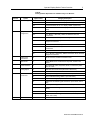
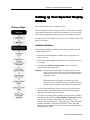
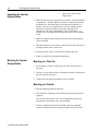
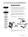
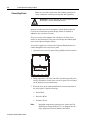
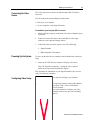
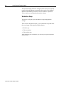
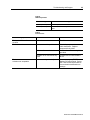
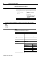
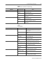
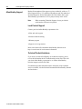
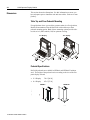
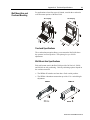
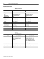
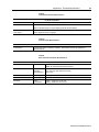
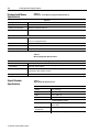
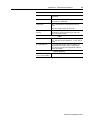
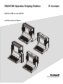
RAC6188 Operator Display Station
Bulletin 6188-A, and 6188-B
Installation and User Manual
2
Table of Contents
6188 Operator Display Station .............................................
Operator Display Station Feature Overview ......................
Part Numbers...........................................................................
Setting up Your Operator Display Station ..........................
Before you Begin ....................................................................
Unpacking the Operator Display Station ................................
Mounting the Operator Display Station ..................................
Making Connections .............................................................
Connecting Power ...................................................................
Connecting the Cat-5 Cable between the Operator
Display Station and the Host Computer Signal Transmitter ...
Installing the Signal Extender .................................................
Connecting the Video Source..................................................
Powering Up the System.........................................................
Configuring Video Setup.........................................................
Setting Up Touchscreen Functionality ....................................
Performing Routine Maintenance .......................................
Cleaning ..................................................................................
Replacing a Line Cord ............................................................
Other Maintenance ..................................................................
Troubleshooting and Support ..............................................
Troubleshooting Solutions ......................................................
Allen-Bradley Support ............................................................
Appendix A: Technical Specifications .................................
Dimensions..............................................................................
Wall Mount Arm and Overhead Mounting..............................
Display Specifications.............................................................
Keyboard and Mouse Specifications.......................................
Signal Extender Specifications ...............................................
3
4
6
9
9
10
10
13
14
15
15
17
17
17
20
21
21
21
21
23
23
28
29
30
31
32
34
34
Important User Information
Solid state equipment has operational characteristics differing from those of
electromechanical equipment. "Safety Guidelines for the Application, Installation, and Maintenance of Solid State Controls"
(Publication SGI-1.1) describes some important differences between solid state equipment and hard-wired electromechanical
devices. Because of this difference, and because of the wide variety of uses for solid state equipment, all persons responsible for
applying this equipment must satisfy themselves that each intended application of this equipment is acceptable.
In no event will Rockwell Automation be responsible or liable for indirect or consequential damages resulting from the use or
application of this equipment. The examples and diagrams in this manual are included solely for illustrative purposes. Because
of the many variables and requirements associated with any particular installation, Rockwell Automation cannot assume
responsibility or liability for actual use based on the examples and diagrams.
No patent liability is assumed by Rockwell Automation with respect to use of the information, circuits, equipment, or software
described in this manual.
Reproduction of the contents of this manual, in whole or in part, without written permission of Rockwell Automation is
prohibited.
Throughout this manual, we use notes to make you aware of safety considerations.
ATTENTION: Identifies information about practices or circumstances that can
lead to personal injury or death, property damage, or economic loss.
Important: Identifies information that is especially important for successful application and understanding of the product.
Operator Display Station Feature Overview
3
ion
6188 Operator Display Stat
Station
The 6188 Operator Display Station is a sealed ergonomic industrial
enclosure that gives your operators one simple, but elegant interface to
applications.
You view an application on the display of the flat panel monitor and use
the keyboard, mouse, or integrated touchscreen to control and monitor
your system.
The slim, attractive, tightly integrated design of the RAC6188 would be
impossible to replicate with an off-the-shelf enclosure. The RAC6188 is
a complete solution, ready to go with no engineering required.
The 6188 incorporates industry-leading Allen-Bradley flat panel
monitors (RAC6185) to give you a bright and easy-to-read display.
Operators need a simple, efficient interface with their application. The
RAC6188 is an ideal solution for your distributed control system or
process control application.
This one-piece operator station connects to any standard PC computer,
and it includes:
• Flat panel monitor the most widely-installed products from our
RAC6185 family of industrial flat panel monitors (6185-C 15.0 in. or
6185-D 18.1 in.)
• Integrated touchscreens for the most intuitive operator interface
• Sealed membrane 101-key keyboard and touch mouse
• Signal extender to allow remote operation up to 400 ft. (122 m) from
the host PC. The extender sends video, keyboard, mouse, and
touchscreen signals over a single, low-cost Cat-5 cable.
This manual provides installation, operation, and maintenance
instructions for the Allen-Bradley 6188 Operator Display Station.
The shipping cartons contain the following items:
• 6188 Operator Display Station
• ScreenSet monitor setup utility
• This user manual
• An Operator Display Station with a touchscreen option ships with
supporting software and manuals on disk or CD
Publication 6188-UM001A-EN-P
4
6188 Operator Display Station
Operator Display Station
Feature Overview
Resolutions
The Operator Display Station auto-syncs to lower resolution video
signals, plus, has on-screen set up menus/controls for any manual
adjustments.
Table A
Resolutions
Flat Panel Display
Size
Resolution
CRT Equivalent
Size
15.0”
640 x 480 to 1024 x 768 (Native)
17”
18.1”
640 x 480 to 1280 x 1024 (Native)
20”
15.0 and 18.1 Specific Features
Capabilities specific to the 15.0 display include the following:
• 1024x768 resolution
• 256K color (18-bit) display
• Bright (200 nits) Active Matrix-TFT 1024x768 display
• Auto-Adjustment function attempts to adjust the settings properly
based on the current signal.
Capabilities specific to the 18.1 display include the following:
• 1280x1024 resolution
• 16m (24-bit) True Color display
• Bright (200 nits) Active Matrix-TFT 1280x1024
Mounting Options
The RAC6188 has four mounting options: Each option gives you the
flexibility to adjust the enclosure for ideal positioning.
• Table Top and Floor Pedestal
For applications where you need the operator station in a fixed
position, Rockwell Automation offers the RAC6188 with a table top
Publication 6188-UM001A-EN-P
Operator Display Station Feature Overview
5
or floor pedestal mounting option. Both of these mounting options
provide side-to-side swivel (180°) and tilt (30°) for optimum viewing.
• Wall Mount Arm and Overhead
For applications where floor or tabletop space is limited, consider the
overhead or wall mount arm options.
The overhead mount option allows you to mount the Operator
Display Station above the operator in a fixed position. This option
gives you 30° tilt adjustment.
Each wall mount arm provides 360° swivel, 30° tilt, and full side-toside positioning. Vertical positioning options depend on the
enclosure material.
Enclosure Options
The RAC6188 can withstand the rigors of your harsh environment. In
addition to its ergonomic design, the RAC6188 is rugged. You can chose
from:
Environmental Rating
Construction Material
NEMA 4/12
NEMA 4X
Painted aluminum,
powder coat finish
Type 316L
Stainless Steel
Remote Operation with Signal Extender
You can install the Operator Display Station up to 400 ft (122 m) away
from any standard PC computer.
You can install the 6188 on the factory floor where the environment is
harsh and space is at a premium, and then connect the Operator Display
Station to the signal transmitter located on the other side of the plant.
Simply connect the signal transmitter to the host PC.
You can connect to the host computer using your own low-cost, twistedpair Cat-5 cable. The video, keyboard, mouse, and touchscreen host
signals are multiplexed across the Cat-5 cable by the transmitter, located
at the computer and the transmitter in the Operator Display Station.
You can even connect an additional monitor, keyboard, and mouse to the
transmitter for backup, troubleshooting, setup and local control. All
power for the signal extender transmitter is supplied by the Operator
Display Station.
Publication 6188-UM001A-EN-P
6
6188 Operator Display Station
Heat Sink Option
For warmer environments, the RAC6188 has an optional heat sink with
internal fans that raises the operating temperature spec to 45°C.
Connections
The 6188 supports standard PS/2 mouse and keyboard connections as
well as AT keyboard and serial mouse connectors and accommodates
standard Windows operating systems
Part Numbers
The part number for your particular unit consists of the Bulletin number
(6188) followed by a ten-digit code indicating the enclosure type,
equipment configuration, and options on your unit.
Following are explanations of the part numbers for the various models of
monitors.
Example:
Publication 6188-UM001A-EN-P
6188
AB
CF
A
A
A
Z
F
Z
1
2
3
4
5
6
7
8
9
Operator Display Station Feature Overview
7
Table B
Catalog Number Explanation for 6185 Economy Line Monitors
Position
2
3
Option
Enclosure Type
Equipment
Configuration
Option Letter
Category Description
AA
L-Series Enclosure for 15 in. display, NEMA 4 (Aluminum)
AB
L-Series Enclosure for 15 in. display, NEMA 4X (Stainless Steel)
BA
L-Series Enclosure for 18.1 in. display, NEMA 4 (Aluminum)
BB
L-Series Enclosure for 18.1 in. display, NEMA 4X (Stainless
Steel)
CA
15 in. Monitor, 1024x768), No Touchscreen
CB
15 in. Monitor, 1024x768), NEMA 4X Stainless Steel, No
Touchscreen
CE
15 in. Monitor, 1024x768), Resistive Antiglare Touchscreen
CF
15 in. Monitor, 1024x768), NEMA 4X Stainless Steel, Resistive
Antiglare Touchscreen
DA
18.1 in. Monitor, 1280x1024), No Touchscreen
DB
18.1 in. Monitor, 1280x1024), NEMA 4X Stainless Steel, No
Touchscreen
DE
18.1 in. Monitor, 1280x1024), Resistive Antiglare Touchscreen
DF
18.1 in. Monitor, 1280x1024), NEMA 4X Stainless Steel, Resistive
Antiglare Touchscreen
4
Power Input/
Connections
A
100 to 132 V AC, Conduit Connection Panel
5
Input Device
A
Sealed NEMA 4/4X 101 Membrane Keyboard, Sealed Touch
Mouse
6
Communications
A
Cat-5 Extender (Video, Keyboard, Mouse, Touchscreen) 400 ft.
max, No Cable
7
Cooling Option
A
Heat Sink with Internal Fans (Mounted on Rear Door)
Z
None
A
Table Top Mounting, NEMA 4 (Tilt and swivel)
B
Floor Pedestal Mounting, NEMA 4 (Tilt and swivel)
C
Overhead Mounting (Tilt)
D
Wall Mount Arm Mounting (Tilt and swivel, up and down, side to
side)
E
Table Top Mounting, NEMA 4X Stainless Steel (Tilt and swivel)
F
Floor Pedestal Mounting, NEMA 4X Stainless Steel (Tilt and
swivel)
G
Overhead Mounting, NEMA 4X Stainless Steel (Tilt)
H
Wall Mount Arm Mounting, NEMA 4X Stainless Steel (Tilt and
swivel, side to side)
Z
None
8
9
Enclosure
Accessories
Future Use
Publication 6188-UM001A-EN-P
Setting up Your Operator Display Station
9
Setting up Your Operator Display
Station
Before you Begin
This section describes how to setting up 6188.
When installing the Operator Display Station, it is important to consider
environmental factors that could affect performance as well as possible
effects from equipment operation on personnel and nearby equipment.
The figure on the left displays the general process to install, connect, and
adjust your monitor.
Installation Guidelines
Following these guidelines will help ensure that the monitor provides
safe and reliable service.
• Ensure that sufficient power is available from a single phase AC
outlet at the site.
• Ensure that sufficient space is available for air circulation necessary
for cooling.
• Ensure that the ambient air temperature will not exceed the
specified maximum temperature.
Important: This Operator Display Station is designed to operate at a
range of extremes, however it is not good design practice to
continuously operate it at the highest end of the specified
temperature range.
While the product will operate at its highest specified
temperature, the overall life span of any electronic device is
shortened when it operates at its highest rated temperature.
• Leave the Operator Display Station’s rear door closed at all times
during operation. The sealed enclosure affords protection against
dust, dirt, and liquids in the environment.
• The Federal Communications Commission has prepared a pamphlet
that addresses the problem of radio frequency interference to radio
and television reception, which should be consulted in case of
problems with such interference. This publication, “How to Identify
and Resolve Radio/TV Interference Problems” (Stock #004-00000345-4) may be obtained from the US Government Printing Office,
Washington, DC 20402.
Publication 6188-UM001A-EN-P
10
6188 Operator Display Station
Unpacking the Operator
Display Station
1. Open the top cap from the
shipping box.
2. Make sure the unit is free from defects, scratches, or other blemishes
in appearance. All Allen-Bradley products are shipped in specially
designed boxes with foam inserts, to minimize the possibility of
damage. However, if a problem has occurred in shipping, please
make note on the bill of lading, contact the shipping carrier
immediately and notify Allen-Bradley of the circumstances. In
addition, save all packing materials and take pictures of the damage
noted.
3. Make sure that the unit(s) and all accessories listed on the packing
slip are included.
4. With the assistance of 2-3 people, carefully lift unit out of the box by
reaching under the unit, on the sides.
5. Place the unit on a flat, level surface for further inspection.
6. Select on of the basic mounting configurations.
Mounting the Operator
Display Station
Mounting on a Table-Top
1. No assembly is required. Simply place the unit onto the table or
bench top.
2. You may want to adjust (tilt) the workstation forward or backward to
the best ergonomic position.
3. Tighten down the palm grip handles to lock it in place.
Mounting on a Pedestal
1. Bolt the mounting pedestal to the floor.
2. Then bolt the workstation to the mounting pedestal using hardware
supplied.
The (4) hole pattern in the 9”x9” top mounting plate matches the
hole pattern in the bottom of the yoke assembly.
3. Tilt the workstation forward or backward to the best ergonomic
position and tighten down the palm grip handles to lock it in place.
Publication 6188-UM001A-EN-P
Setting up Your Operator Display Station
11
Mounting Using a Flex Arm
1. Bolt the flex arm mounting plate to the mounting surface (wall or tall
pedestal) using the hardware supplied.
2. Then remove the yoke from the Operator Display Station enclosure
and mount it to the swivel part of the flex arm using the hardware
provided.
3. Re-assemble the yoke to the Operator Display Station enclosure
using the two side-mount palm grip handles. This may require 1 or 2
people to hold the enclosure while installing the palm grip handle
studs through the yoke index plates and into the workstation yoke
mounts.
4. Tilt the workstation forward or backward to the best ergonomic
position and tighten down the palm grip handles to lock it in place.
WARNING: Once installed into the yoke, do not loosen
the palm grip handles more that 1 or 2 turns while
adjusting the workstation’s tilt position. Unscrewing the
palm grip handles to far can cause the workstation to
detach from the yoke and drop.
Mounting Overhead
1. Remove the yoke from the Operator Display Station.
2. Bolt the yoke to an overhead surface.
3. Re-assemble the yoke to the Operator Display Station enclosure
using the two side-mount palm grip handles. This may require 1 or 2
people to hold the enclosure while installing the palm grip handle
studs through the yoke index plates and into the workstation yoke
mounts.
4. Tilt the workstation forward or backward to the best ergonomic
position and tighten down the palm grip handles to lock it in place.
Publication 6188-UM001A-EN-P
Making Connections
13
Making Connections
The RAC6188 gives you great flexibility— you can install the Operator
Display Station up to 400 ft (122 m) away from any standard PC
computer. After installing the RAC6188 on the factory floor, you then
connect the RAC6188 to the signal transmitter located on the other side
of the plant, and connect the signal transmitter to the host PC.
The RAC6188 connects to the host computer using your own low-cost
CAT-5 cable. The RAC6188 sends video, keyboard, mouse, and
touchscreen signals across the CAT-5 cable to the transmitter.
You can even connect an additional monitor, keyboard, and mouse to the
transmitter for easy troubleshooting, setup and local control. The
Operator Display Station internal cables for video, keyboard,
touchmouse and optional touchscreens are factory-installed to the signal
extender.
All power for the signal extender and transmitter is supplied by the
Operator Display Station.
In the figure on the left, the gray shaded areas represent where you are
now in the general process to install, connect, and adjust your Operator
Display Station.
Publication 6188-UM001A-EN-P
14
6188 Operator Display Station
Make sure you follow local codes and company procedures to
ensure compliance with all governing rules and regulations.
Connecting Power
WARNING: Prior to bringing any electrical power to the
Workstation, read the following section.
Install all conduits and wire in accordance with the National Electric
Code for the area that the Operator Display Station is installed, in
addition to any relevant local codes.
The power source must originate from a dedicated 15 Amp circuit
breaker or fused disconnect. This source should provide uninterrupted
power to the Operator Display Station.
You need to supply Power wiring to the Operator Display Station via
conduit through the lower-rear access panel.
1. Open the lower rear access panel using a phillips-head screwdriver.
2. Bring single phase, 120 VAC (240 VAC Optional) electrical power
into the workstation via the lower rear access panel. The rear panel
can be tapped to accept conduit entry.
3. Route the wires to the main terminal block, located on the back of
the access panel. Using the following:
•
Hot to Black
•
Neutral to White
•
Ground to Green.
Note:
Publication 6188-UM001A-EN-P
Integrated components requiring power, such as the Flat
Panel Display, Signal Extender, etc., are plugged into the
Surge Suppressor when assembled at the factory.
Making Connections
Connecting the Cat-5
Cable between the
Operator Display Station
and the Host Computer
Signal Transmitter
15
Install your computer in a Local (Safe) Location some distance from the
Operator Display Station to protect it from the harsh environment. This
area should be compatible with your computer’s environmental needs.
1. Bring the Cat-5 (UTP)
communications cable into the
Operator Display Station via the
lower rear access panel.
2. Route this cables into the Operator Display Station separately from
the power cable.
3. Route Cat-5 (UTP) communications cable to the signal extender
receiver mounted on the rear door of the enclosure.
Installing the Signal
Extender
The Signal Extender is simple-to-install, and no software or expensive
networking is required. There are no switch setting changes required to
adapt to the connected peripherals.
The advanced circuitry provides automatic compensation for different
cable lengths, video resolutions and COM serial port data rates.
Signal Extender Receiver
The Signal Extender Receiver unit is factory installed in the 6188 with
the video, PS/2 keyboard, PS/2 touchmouse and optional serial
touchscreen cables pre-wired.
The extender power supply is included, mounted, and pre-wired to the
Receiver unit inside the Operator Display Station enclosure.
Signal Extender Transmitter
The Signal Extender Transmitter module comes as a boxed accessory
with your system. This must be installed at the host computer.This
includes the following:
• Transmitter box
• Custom prefabricated cable bundle that has Video, Keyboard and
Touchmouse cables all terminating into one 25 pin D-sub connector
marked “CUFC-GC”.
• Serial cable for computer connection of the touchscreen will also be
included if you purchased the touchscreen option.
The Signal Extender Transmitter module also supports a local monitor,
keyboard and mouse for redundant control, troubleshooting, backup and
hardware and software maintenance.
Publication 6188-UM001A-EN-P
16
6188 Operator Display Station
Signal Extenders Power
There are no power On/Off switches on either unit so they will be
functional once power is applied.
WARNING: Do not install a power supply on the
Transmitter unit since required power is transmitted from
the Receiver side over the Cat-5 extender cable.
Connecting the Signal Extender
Your Signal Extender Transmitter module comes with a KVM-extension
cable used to connect to your IBM PC compatible computer.
Connect the Transmitter Signal Extender Extension Module
1. Power down the computer.
2. Identify the KVM-extension custom bundled cable (CUFC-GC).
These cables have one 25 pin D-sub connector
•
The keyboard cable has PS/2 and AT style connectors on the end
for support of either type system.
•
The mouse cable has a PS/2 and 9-pin serial connectors on the
end for support of either a PS/2 or serial mouse.
•
The video cable (the larger one) has a HD-15 connector on the
end.
3. Plug the 25-pin connector into the matching 25-pin female connector
on the front panel of the Transmitter module.
4. Take the KVM connectors at the other end and plug them into the
applicable computer ports, being careful not to switch the
keyboard/mouse cables.
5. Plug the touchscreen (Optional) serial cable from the serial port on
the Transmitter to a serial port on your computer.
Note:
Publication 6188-UM001A-EN-P
Do not forget that you must load the touchscreen driver
onto your computer and calibrate it for the touchscreen
to function.
Making Connections
Connecting the Video
Source
17
The video connection to the host is made through a HD-15 (female)
connector.
You can connect the Operator Display Station either:
• Directly to your computer
• To your computer via the Signal Extender
To establish a signal using the HD-15 connector:
1. Obtain a shielded, properly terminated video cable of length as short
as possible
2. Connect one end of the cable to the female HD-15 video input
connector on the Operator Display Station.
3. Connect the other end to the output to one of the following:
Powering Up the System
•
Signal Extender
•
IBM-compatible VGA adapter
To power up the other devices attached to the Extender units, take these
steps:
1. Power up the CPU and your computer’s display, if necessary.
Your CPU should boot normally - sensing the video, optional
touchscreen, keyboard and touchmouse signals.
This completes the installation of your Signal Extenders; they are now
ready for continuous operation.
Configuring Video Setup
This section describes how to setup and configure your Operator
Display Station.
Important: Since the 6188 incorporates industry-leading Allen-Bradley
flat panel monitors (RAC6185), we have included the
appropriate RAC6185 manual.
Use the procedure in this manual to configure your video
setup. The information in this section provides a summary
of the overall process.
Publication 6188-UM001A-EN-P
18
6188 Operator Display Station
The Operator Display Station is configured at the factory, but typically
requires initial adjustments to match the video card in your computer.
Rockwell Automation provides the Flat Panel Monitor Adjustment
Utility to assist you in adjusting the monitor settings.
Workstation Setup
You need to verify that your workstation is using the appropriate
settings.
There are three important aspects of your workstation setup that affect
the screen image of the Operator Display Station:
• Monitor type
• Video resolution
• Video refresh rate
After setting up your workstation, you are ready to begin to adjust the
monitor itself.
Publication 6188-UM001A-EN-P
Making Connections
19
Push Buttons
The Operator Display Station provides push buttons on the rear of the
monitor to adjust the following settings:
• Brightness
• Contrast
• Position Information
By using the Flat Panel Monitor Adjustment Utility and push buttons on
the rear of the monitor you can adjust these settings. The push buttons
control the monitor’s On-screen display (OSD).
The following table provides a summary to using the pushbuttons:
Table C
Pushbutton Summary
The Select Pushbutton…
The Up and Down Pushbuttons…
Starts the OSD.
Highlight the option you want.
Selects a highlighted option.
Adjust the selected option higher or
lower.
Saves the value and returns to the
previous menu.
Publication 6188-UM001A-EN-P
20
6188 Operator Display Station
Setting Up Touchscreen
Functionality
Touchscreen provides an additional method of operator interface.
1. You must install a software
driver on your computer to handle communications with the
touchscreen controller.
Install the software on the host computer using the installation disks
or CD included with the system accessories.
All touchscreen controllers are configured by default to provide
serial communications at 9600 baud, 8 data bits, 1 stop bit, no parity.
2. Perform a calibration on the touchscreen display by doing the
following:
a. Select the Start button and select Settings to access Control
Panel.
b. In Control Panel, select Elo Touchscreen/Monitor Mouse.
c. Select the General tab and click on the Calibrate button.
d. Touch the three reference targets that appear.
e. Follow the directions that are presented
Because the touchscreen emulates a mouse, there may be compatibility
issues involving how the touchscreen emulates mouse buttons, especially
multiple buttons.
For more information, refer to the touchscreen documentation included
with the touchscreen software.
Publication 6188-UM001A-EN-P
Performing Routine Maintenance
21
Performing Routine Maintenance
Cleaning
Occasionally clean the Operator Display Station with a soft cloth
dampened (not soaked) with a mild (non-abrasive) glass cleaner. Keep
turning a fresh side of the cloth toward the screen surface to avoid
scratching it with accumulated grit.
Note:
The solvent should be applied only to the cloth, and not
directly on the monitor screen.
Do not use paper products as they may scratch the surface.
To minimize the risk of abrasion, allow the screen to
stand dry.
ATTENTION: You can use alcoholic or ammoniacal
cleaners to clean the polycarbonate shield or a
touchscreen. However, use only one or the other at all
times. A residue mixture can cause a chemical reaction.
Special care should be taken when cleaning a touchscreen or
polycarbonate shield that is installed over the screen. Abrasive and
certain chemical cleaners can easily damage the surface.
Replacing a Line Cord
To avoid shock and fire hazards, the Operator Display Station’s power
cord should be replaced if the insulation becomes broken or if it develops
a loose internal connection.
Other Maintenance
Qualified service personnel should perform all maintenance, except for
the power cord replacement described above.
Publication 6188-UM001A-EN-P
Troubleshooting and Support
Troubleshooting
Solutions
This section covers some typical problems you may encounter. The
following identifies symptoms, possible problems and solutions for
workstation components including the Flat Panel Display, Touchscreen,
Keyboard w/Touchmouse, Signal Extender and Fiber Signal Extender.
The Troubleshooting Tables are arranged as follows:
• Flat Panel Displays
• LED Interpretation – Flat Panel Displays
• Touchscreens
• Keyboard with Touchmouse
• Signal Extender
Refer to this table to help identify the cause and offer a solution to a
problem. This table lists typical problems you may encounter.
Table D:
Troubleshooting Table
Symptom
Status LED does not come on.
Possible Problem
Action
Display or video source off.
Turn on display, power source or
video source.
Power cord not connected.
Reconnect power cord.
Power cord faulty.
Replace power cord.
Monitor faulty.
Have monitor serviced.
Screensaver or energy saver
activated by workstation.
Disable screen saver by activating
input device.
Contrast control not properly
adjusted.
Turn the contrast control UP using
on-screen menu or luminance control
on the 18"
Video cable problem
Check for proper installation of video
cable. Replace suspected faulty
cable.
Image is too bright or white
Contrast control not properly
adjusted.
Turn the contrast control DOWN
using on-screen menu.
No image visible even when
brightness control is set full UP
Monitor is out of adjustment or faulty.
Have monitor serviced.
Video cable problem
Check for proper installation of video
cable. Replace suspected faulty
cable.
Screen is blank.
Publication
24
6188 Operator Display Station
Symptom
Fault in video source
Test video source by connecting to
known good monitor.
Fault in monitor
Have monitor serviced.
Possible Problem
Action
Image is not centered.
Position controls are not properly
adjusted.
Reset horizontal and vertical
positioning using display on-screen
menu. Check to see if video source
is operating within monitor’s range.
Image will not adjust.
Video timing outside of range.
Use on-screen menu to adjust the
phase control. Make sure timing is
set within guidelines.
Image position changes are not
saved.
Position mode no exited correctly.
Reposition the image using onscreen menu and select EXIT to save
the changes/exit.
Image is not stable
Monitor is not synched to video
source.
Check for proper video cable
installation. Replace suspected faulty
cable. Check to ensure that video
source is operating within monitor’s
range. Adjust Phase control using
on-screen menu.
Image not properly centered or sized.
Size and position controls incorrectly
adjusted.
Adjust controls for proper size/
position using onscreen menu.
Vertical shaded bars on screen
image.
Horizontal size not properly adjusted.
Adjust horizontal size setting using
on-screen menu.
Colors are missing.
Video cable problem
Check for proper video cable
installation. Replace suspected faulty
cable.
Fault in monitor
Have monitor serviced.
Monitor clock phase not properly
adjusted.
Adjust monitor clock phase setting
using on-screen menu.
Video cable problem
Check for proper video cable
installation. Replace suspected faulty
cable.
Electrical noise interference from
nearby equipment
Check for proper video cable
installation. Re-route cables or
replace suspected faulty cables.
Check host and monitor ground.
Slight distortion in text or graphics.
Not operating monitor in native
resolution
Change the Expand/Center settings
using the on-screen menu or change
the video source to native resolution.
Screen image does not fill the display
Not operating monitor in native
resolution
Change the Expand/Center settings
using the on-screen menu or change
the video source to native resolution.
Image has blurry streaks or
“ghosting” to the right of objects on
the screen. Screen lacks one or two
colors.
Contrast is set too high or overdriven
video if full range dimming option is
installed.
Adjust brightness and contrast
settings using on-screen menu.
Calibrate video gain using on-screen
menu.
Video cable problem.
Check for proper video cable
installation. Replace suspected faulty
cable.
Screen jitter or noisy video
NOTE: The On-Screen Menu can be activated and navigated using the SELECT, UP & DOWN buttons on the rear
panel of the flat panel display.
Publication 6188-UM001A-EN-P
Troubleshooting and Support
25
Table E
LED Interpretation
Heading
Heading
GREEN (SOLID)
Normal Operation
AMBER (SOLID)
Power ON, loss of video sync or disconnected video
cable.
Table F
Touchscreens
Symptom
Possible Problem
Action
Touchpoint different from area
touched.
Calibration
Recalibrate touchscreen
Touchscreen does not work.
Touchscreen cable problem
Check for proper touchscreen
cable installation. Replace
suspected faulty cable.
Software driver not loaded.
Install software driver using disk
provided.
Software driver load did not fully
install.
Uninstall and re-install software
driver.
Software settings need adjusted
On computer go to START,
Settings & Control Panel. Select
Elo Touchscreen Monitor Mouse
Icon and make modifications to
settings.
Touchmouse movement or
activation not acceptable.
Publication 6188-UM001A-EN-P
26
6188 Operator Display Station
Table G
Installing the Touchscreen Driver Software
1.
Open the file.
From an unzipped downloaded file:
If you are using 95/98
If you are using Windows NT
•
Double-click setup.exe in the
elowin95 folder.
•
Start NT Explorer
•
•
Follow the installation
directions
Right-click on the Start
button
•
Click Explore
•
Double-click the setup.exe
file in the EloNT directory
and follow the installation
directions.
From a shipped diskette:
•
Double-click setup.exe on the diskette
•
Follow the installation directions
2.
If more than one COM port is available, you will select the port your touchscreen cable is connected to.
3.
The calibration displays automatically. Calibrate the monitor by touching in the following corners of the
display:
•
Upper left
•
Lower right
•
Upper right
Table H
Uninstalling the Touchscreen Driver Software
If you are using 95/98
If you are using Windows NT
Click on the Start button.
Click on the Start button.
Select Control Panel.
Select Control Panel.
Double-click Add/Remove
Programs.
Double-click Add/Remove Programs.
Double-click Monitor Mouse
for Windows 95.
Double-click MonitorMouse for Windows NT.
Click OK.
Click Yes.
Using Explorer, delete the
elowin95 folder.
Using Explorer, delete the ElowinNT and
EloNt folders.
Reboot.
Using Explorer, delete the following files:
Files
Locations
monmouse.cpl
winnt/system32
monmouse.sys
winnt/system32/d
rivers
elocal32.exe
winnt/system32
mmstub.sys
winnt/system32/d
rivers
Reboot.
Publication 6188-UM001A-EN-P
Troubleshooting and Support
27
Table I
Keyboard with Touchmouse Troubleshooting
Symptom
Possible Problem
Action
Keyboard or Touchmouse not working
Computer off
Turn on computer or power source.
Keyboard not functioning
Keyboard cable
problem
Check for proper keyboard cable installation. Replace
suspected faulty cable.
Keyboard faulty
Install in known good computer to confirm fault.
Replace or service keyboard.
Computer faulty
Substitute known good keyboard on computer to
confirm fault.
Touchmouse cable
problem
Check for touchmouse cable installation. Replace
suspected faulty cable.
Touchmouse faulty
Install touchmouse in known good computer to confirm
fault. Have unit replaced or serviced.
Computer faulty
Substitute known good touchmouse on computer to
confirm fault.
Touchmouse not functioning
Table J
Signal Extender
Symptom
POWER indicator (s) not lit
No video or poor video quality
No keyboard/mouse operation
No touchscreen operation
Possible Problem
Action
Power supply
Verify that power supply is connected to Receiver
unit. Verify 120VAC power source and 24VDC
supply output.
Cat-5 extension cable
Check Cat-5 extension cable is connected at both
ends.
Computer off
Turn on computer
Transmitter/Receiver
video cable
Check for proper video cable installation. Replace
suspected faulty cable.
Display problem
Ensure display is working correctly by connecting
it directly to computer.
Cat-5 extension cable
length
Verify length of Cat-5 extension cable is within
tolerable limits for resolution & refresh rate.
Transmitter/Receiver
Keyboard/Mouse cables
Check for proper keyboard /mouse cable
installation. Replace suspected faulty cable.
Keyboard/mouse cables
Ensure keyboard/mouse cables are plugged into
the correct jacks, then reboot.
Cat-5 extension cable
connection
Check Cat-5 extension cable is connected at both
ends.
Keyboard/mouse
problem
Ensure keyboard/mouse is working correctly by
plugging it directly to the computer.
Transmitter/Receiver
touchscreen cables
Check for proper touchscreen cable installation.
Replace suspected faulty cable.
Cat-5 extension cable
Check Cat-5 extension cable is connected at both
ends.
Touchscreen problem
Ensure touchscreen is working correctly by
connecting it directly to computer.
Publication 6188-UM001A-EN-P
28
6188 Operator Display Station
Allen-Bradley Support
Rockwell Automation offers support services worldwide, with over 75
Sales/Support Offices, 512 authorized Distributors and 260 authorized
Systems Integrators located throughout the United States alone, plus
Allen-Bradley representatives in every major country in the world.
Note:
When contacting Technical Support, always provide the
serial number of the unit in question.
Local Product Support
Contact your local Allen-Bradley representative for:
• Sales and order support
• Product technical training
• Warranty support
• Support service agreements
Refer to the Rockwell Automation/Allen-Bradley Internet site at
http://www.ab.com for local contact information.
Technical Product Assistance
If you need to contact Allen-Bradley for technical assistance, please
review the information in the Troubleshooting section first. Then call
your local Allen-Bradley representative or contact Allen-Bradley
technical support at (440) 646-5800.
For additional product information and a description of the technical
services available, visit the Rockwell Automation/Allen-Bradley Internet
site listed above.
Publication 6188-UM001A-EN-P
Appendix A: Technical Specifications
29
Appendix A: Technical
Specifications
Materials
Enclosure
• Painted Aluminum (NEMA 4) or
• Stainless Steel 316L (NEMA 4X)
Pedestal
• Painted Steel (NEMA 4) or Stainless Steel (NEMA 4X)
Paint (NEMA 4)
• Crowe Industries Powder Coat (or equivalent) or
• Sherwin-Williams Polane T-Plus (or equivalent)
Weight (Approximate)
Table K
Weight Specifications
Enclosure
NEMA 4
NEMA 4X
Note:
Display Size
Weight
15.1” Display
50 Lbs.
18.1” Display
59 Lbs.
15.1” Display
74 Lbs.
18.1” Display
83 Lbs.
Weight estimate includes yoke.
Additional options will add to the total weight.
Electrical Requirements:
Power
• 15 Amps. Maximum – 120 VAC, 60 Hz
• (Optional 220-240 VAC, 50Hz)
Outlets
• 8-Outlet Surge Suppressor
Publication 6188-UM001A-EN-P
30
6188 Operator Display Station
Dimensions
This section shows the dimensions. Use this information to ensure you
have adequate space to install the unit and route cables. Units are in mm
[inches].
Table Top and Floor Pedestal Mounting
For applications where you need the operator station in a fixed position,
Rockwell Automation offers the RAC6188 with a table top or floor
pedestal mounting option. Both of these mounting options provide sideto-side swivel (180°) and tilt (30°) for optimum viewing.
15.1 Display
18.1 Display
Pedestal Specifications
RAC6188 pedestals are available in NEMA 4 and NEMA 4X stainless
steel. The height of the pedestal varies according to the size of the flat
panel display selected
• 15.1 Display
749.3 [29.50]
• 18.1 Display
952.5 [37.50]
NEMA 4
Publication 6188-UM001A-EN-P
NEMA 4X
Appendix A: Technical Specifications
Wall Mount Arm and
Overhead Mounting
31
For applications where floor space is limited, consider the overhead or
wall mount arm options of the RAC6188.
15.1 Display
18.1 Display
Overhead Specifications
The overhead mount option allows you to mount the RAC6188 above
the operator in a fixed position. This option gives you 30° tilt
adjustment.
Wall Mount Arm Specifications
Each wall mount arm for the RAC6188 provides 360° swivel, 30° tilt,
and full side-to-side positioning. Vertical positioning options depend on
the enclosure material:
• The NEMA 4X stainless steel arm has a fixed vertical position.
• The NEMA 4 aluminum construction provides 12 in. vertical height
adjustment.
NEMA 4
NEMA 4X
Publication 6188-UM001A-EN-P
32
6188 Operator Display Station
Display Specifications
Table L
Display Specifications
Display
Type
15.0” Flat Panel
18.1” Flat Panel
Active Matrix Color Thin Film Transistor (TFT) LCD
Backlight
Type
Cold Cathode Tube (CCT)
Cold Cathode Tube (CCT)
Life Expectancy
50,000 Hours (Typical)
50,000 Hours (Typical)
Field Replacement
Yes
No
Diagonal
15.1 In. (383 mm)
18.1 In. (460 mm)
Horizontal
12.0 In. (304 mm)
14.1 In. (359 mm)
Vertical
9.0 In. (228 mm)
11.3 In. (287 mm)
Resolution
1024 x 768 pixels, 256K colors
1280 x 1024 pixels, full color
Horizontal(Typical)
+/- 60 Deg.
+/- 85 Deg.
Vertical (Typical)
+ 55/- 45 Deg.
+/- 85 Deg.
Luminance (Typical)
200 nit, 58fL (screen overlay option reduces luminance)
Contrast Ratio(Typical)
250 : 1
100 : 1
Response Time
35 msec (Typical)
45 msec (Typical)
Nominal Display Area
Viewing Angle
Table M
Video Specifications
Video
Supported Standards
15.1” Flat Panel
18.1” Flat Panel
640 x 480 @ 60Hz and 75Hz
720 x 400 @ 70Hz (VGA text)
800 x 600 @ 60Hz and 75Hz
640 x 480 @ 60Hz and 75Hz
1024 x 768 @ 60Hz (Native)
800 x 600 @ 60Hz and 75Hz
and 75Hz
1024 x 768 @ 60Hz and 75Hz
1280 x 1024 @ 60Hz and 75Hz
(Native)
Video Input Signal
RGB analog (white level = 0.714V above
ref. Black, into 75 Ohms
RGB analog (white level = 0.714V above
ref. Black, into 75 Ohms
Sync Input Signals
H & V separate (TTL levels, positive or
negative)
H & V separate (TTL levels, positive or
negative)
Input Connection
HD-15
HD-15
Publication 6188-UM001A-EN-P
Appendix A: Technical Specifications
33
Table N
Controls & Indicators Specifications
Controls & Indicators
Front Panel
Luminance with Status LEDs (18” Display Only)
Back Panel
Access on-screen display (Top Button)
Adjust controls through on-screen display (Second and third button)
On-Screen Display and
Auto Adjust
Horizontal Size, Vertical Position, Horizontal Position, Contrast, Brightness, Clock
Phase, Expand/ Center, Language
Table O
Operator Input Specifications
Controls & Indicators
Touchscreen
Touchscreen Option – Resistive Antiglare , with Serial Controller using DOS and
Windows drivers
Table P
Environmental and Power Specifications
Environmental and Power Specifications
Environmental
Electrical
Electrical
Rating
NEMA 4/12 (IP65) Painted Aluminum Enclosure
NEMA 4X (IP65) Stainless Steel Enclosure
Temperature:
Operating
Non-Operating
0C to 40C (45C with optional heat sink)
-20C to 65C
Line Voltage
100 to 132 VAC
Line Frequency
50-60Hz
Power
Consumption
6185-C – 61W max, 75 VA max
6185-D – 86W max, 100 VA max
Publication 6188-UM001A-EN-P
34
6188 Operator Display Station
Keyboard and Mouse
Specifications
Table Q
Keyboard – Uses Mouse (Integrated) Specifications
Physical
Rating
NEMA 4 / 4X
Keys
Embossed for enhanced feel
Overlay Characteristic
Wear and chemical resistant
Language
English Standard
Mechanical
Keys
Sealed Mechanical
Cutout for Integrated Mouse
Key Operation
0.4 mm
Key Life Expectation
> 20 million switch cycles
Key Operating Force
150 gms (nominal)
Table R
Mouse (Integrated) Specifications
Mouse (Integrated)
Material
Industrial Silicone Rubber
Compatibility
Microsoft, PS/2, Ligitech
Features
Full rotation travel and positive directional positioning;
Proprietary Fujitsu position sensors
Rating
NEMA 4 and NEMA 4X
Signal Extender
Specifications
Table S
Signal Extender Specifications
Mechanical – Transmitter
Weight:
1 Lb. (0.45 kg)
Height:
1.9 In. (48 cm)
Width:
8.1 In. (206 cm)
Depth:
4.8 In. (122 cm)
Environmental / Power
Publication 6188-UM001A-EN-P
Power Supply:
24 VDC @ 500 mA supplied from RAC6188 through
Cat-5 cable.
Operating
Temperature:
0 Deg. C to +40 Deg. C
Storage Temperature:
-20 Deg. C to +50 Deg. C
Appendix A: Technical Specifications
35
Supported Hardware
Computers:
Computers using 100% IBM PS/2 compatible
peripherals.
Video Modes
Non-interlaced VGA, SVGA, XGA, SXGA
640 x 480 up to 1280x1024
Peripherals
PS/2 or Serial Mouse, PS/2 Keyboard (150 mA
max.)
VGA, HD-15 high density “D” connector
Serial Port (Or Serial
Mouse)
EIA-232 async up to 19.2 Kbps, 9-pin “D” connector
(female to PC, male to peripheral) TD, RD, RTS,
CTS, DTR, DSR, Ground
Audio
To Speakers
3.5 mm stereo jack for powered speakers, 3 Vpp
max., 200 ohms output impediance, < 0.01% THD at
1 KHz
From Microphone
3.5 mm stereo/mono jack, 5.6K ohm pullup for 2
powered electret microphones in a single stereo
jack, dynamic microphone supported with reduced
volume and quality
Agency Approvals
FCC class A, UL, CUL, CE, VCCI Class A
Publication 6188-UM001A-EN-P
IBM is a registered trademark of International Business Machines Corporation.
VGA is a trademark of International Business Machines Corporation.
PC AT is a trademark of International Business Machines Corporation.
Microsoft is a registered trademark of Microsoft Corporation.
Microsoft Windows is a trademark of Microsoft Corporation.
AccuTouch is a trademark of Elo TouchSystems.
ClearTek is a trademark of Microtouch.
Copyright 2001 Rockwell Automation Corporation. All rights reserved. Printed in USA.
Publication 6188-UM001A-EN-P
41061-213-01(A)
998087-0101