1
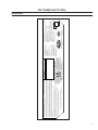
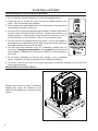
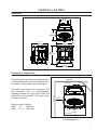
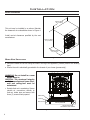
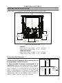
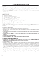
SHERWOOD INDUSTRIES IS AN ENVIRONMENTALLY RESPONSIBLE COMPANY. THIS MANUAL IS PRINTED ON RECYCLED PAPER.
PLEASE KEEP THESE INSTRUCTIONS FOR FUTURE REFERENCE
PELLET STOVE
Empress-A-FS
TECHNICAL MANUAL
Contact your building or fire officials about restrictions and installation
inspection requirements in your area.
PLEASE READ THIS ENTIRE MANUAL BEFORE INSTALLATION
AND USE OF THIS PELLET-BURNING ROOM HEATER. FAILURE TO
FOLLOW THESE INSTRUCTIONS COULD RESULT IN PROPERTY
DAMAGE, BODILY INJURY OR EVEN DEATH.
50-1267
Table of Contents
Introduction...................................................................................................................................3
Rating Label Location...........................................................................................................3
Important Safety Data.........................................................................................................3
Safety Warnings And Recommendations................................................................................3
Installation.....................................................................................................................................5
Deciding Where to Locate your Pellet Appliance.....................................................................5
Removing Pellet Stove From Pallet........................................................................................5
Dimensions.........................................................................................................................6
Clearances to Combustibles..................................................................................................6
Alcove Clearances................................................................................................................7
Mobile Home Installation......................................................................................................7
Exhaust And Fresh Air Intake Locations.................................................................................8
Outside Fresh-Air Connection................................................................................................8
Vent Termination Requirements.............................................................................................9
Corner Through Wall Installation.........................................................................................10
Horizontal Exhaust Through Wall Installation........................................................................10
Vertical Rise with Horizontal Termination Installation (Recommended)....................................12
Through Concrete Wall With Vertical Rise Installations..........................................................12
Inside Vertical Installations.................................................................................................13
Outside Vertical Installations...............................................................................................14
Hearth Mount Installation...................................................................................................15
Installation with Exterior Mounted Exhaust Blower................................................................16
Through Wall Vertical Installation With Exhaust Blower..........................................................18
Thermostat Installed..........................................................................................................19
Slider/Damper Setting........................................................................................................19
Troubleshooting............................................................................................................................21
Wiring Diagram.............................................................................................................................24
Parts List - Components...............................................................................................................25
Parts List - Cast...........................................................................................................................27
Parts Diagram - Components..........................................................................................................29
Parts Diagram - Steel & Cast..........................................................................................................30
Warranty......................................................................................................................................31
Installation Data Sheet..................................................................................................................34
2
Introduction
* This manual is designed for the technician in conjunction with the owner’s manual. *
IMPORTANT SAFETY DATA:
Please read this entire Owner’s Manual before installing or operating this ENVIRO Pellet
Stove. Failure to follow these instructions may result in property damage, bodily injury
or even death. Contact your local building or fire official to obtain a permit and any information on
installation restrictions and inspection requirements for your area.
To prevent the possibility of a fire, ensure that the appliance is properly installed by adhering
to the installation instructions. An ENVIRO dealer will be happy to assist you in obtaining information
with regards to your local building codes and installation restrictions.
Be sure to maintain the structural integrity of the home when passing a vent through walls, ceilings, or
roofs.
The stove’s exhaust system works with negative combustion chamber pressure and a slightly positive
chimney pressure. It is very important to ensure that the exhaust system be sealed and airtight. The ash
pan and viewing door must be locked securely for proper and safe operation of the pellet stove.
Do not burn with insufficient combustion air. A periodic check is recommended to ensure proper
combustion air is admitted to the combustion chamber. Setting the proper combustion air is achieved by
adjusting the slider damper located on the left side of the stove.
When installing the stove in a mobile home, it must be electrically grounded to the steel chassis of the
home and bolted to the floor. Make sure that the structural integrity of the home is maintained and all
construction meets local building codes.
Minor soot or creosote may accumulate when the stove is operated under incorrect conditions such as an
extremely rich burn (black tipped, lazy orange flames).
If you have any questions with regard to your stove or the above-mentioned information, please feel free
to contact your local dealer for further clarification and comments.
SAFETY WARNINGS AND RECOMMENDATIONS:
Caution: Do not connect to any air distribution duct or system.
Do not burn garbage or flammable fluids such as gasoline, naptha or engine oil.
Unit hot while in operation. Keep children, clothing and furniture away. Contact
may cause skin burns.
SOOT: Operation of the stove with insufficient combustion air will result in the formation of soot which
will collect on the glass, the heat exchanger, the exhaust vent system, and may stain the outside of the
house. This is a dangerous situation and is inefficient. Frequently check your stove and adjust the slider/
damper as needed to ensure proper combustion. See: “INSTALLATION - SLIDER/DAMPER SETTING”.
3
Introduction
ELECTRICAL: The use of a surge protected power bar is recommended. The unit must be
grounded. The grounded electrical cord should be connected to a standard 120 volts, 60 hertz electrical
outlet and also must be accessible. If this power cord should become damaged, a replacement power
cord must be purchased from the manufacturer or a qualified ENVIRO dealer. Be careful that the electrical
cord is not trapped under the appliance and that it is clear of any hot surfaces or sharp edges. This unit’s
maximum power requirement is (4.1 Amps) 500 watts.
GLASS: Do not abuse the glass by striking or slamming the door. Do not attempt to operate the stove
with broken glass. The stove uses ceramic glass. Replacement glass must be purchased from an ENVIRO
dealer. Do not attempt to open the door and clean the glass while the unit is in operation or if glass is
hot. To clean the glass, use a soft cotton cloth and mild window cleaner, gas or wood stove glass cleaner,
or take a damp paper towel and dip into the fly ash. This is a very mild abrasive and will not damage the
glass.
FLAMMABLE LIQUIDS: Never use gasoline, gasoline-type lantern fuel, kerosene, charcoal lighter
fluid, or similar liquids to start or “freshen up” a fire in the heater. Keep all such liquids well away from
the heater while it is in use.
SMOKE DETECTOR: Smoke detectors should be installed and maintained in the structure when
installing and operating a pellet burning appliance.
OPERATION: The ash pan and door must be closed securely for proper and safe operation of the pellet
stove. Also ensure all gaskets on the door are checked and replaced when necessary.
INSTALLATION: Be sure to maintain the structural integrity of your home when passing a vent through
walls, ceilings, or roofs. It is recommended that the unit be secured into its position in order to avoid any
displacement.
DO NOT INSTALL A FLUE DAMPER IN THE EXHAUST VENTING SYSTEM OF THIS UNIT.
DO NOT CONNECT THIS UNIT TO A CHIMNEY FLUE SERVING ANOTHER APPLIANCE.
FRESH AIR: Outside Fresh Air is optional. Consider all large air moving devices when installing your unit
and provide room air accordingly. Limited air for combustion may result in poor performance, smoking
and other side effects of poor combustion.
If you have any questions with regards to your stove or the above-mentioned information, please feel
free to contact your local dealer for further clarification and comments.
SINCE SHERWOOD INDUSTRIES LTD. HAS NO CONTROL OVER THE INSTALLATION OF
YOUR STOVE, SHERWOOD INDUSTRIES LTD. GRANTS NO WARRANTY IMPLIED OR STATED
FOR THE INSTALLATION OR MAINTENANCE OF YOUR STOVE. THEREFORE, SHERWOOD
INDUSTRIES LTD. ASSUMES NO RESPONSIBILITY FOR ANY CONSEQUENTIAL DAMAGE(S).
SAVE THIS INSTRUCTION MANUAL FOR FUTURE REFERENCE
RATING LABEL LOCATION:
The rating label is located on the inside of the hopper lid.
4
J
F
M
A M J
J
A
S
O
N
D
2005
2006
DATE OF MANUFACTURE / DATE DE FABRICATION:
2007
Pour l'usage avec les combustibles sous forme de boulets uniquement. Fonctionner seulement avec la vue de porte et la porte
d'enlèvement de cendre ont fermé. Seulement remplacer le verre avec le verre de ceramique. Les composants ont exigé pour
l'installation : 3 pouce (75 mm) ou 4 pouce (100 mm) a énuméré le conduit de PL complète avec les composants. Les
installations de mont de foyer ; un paquebot de cheminée de mur de seul énuméré peut être utilisé.
For Use With Only Pelletized Wood fuels. Operate only with viewing door and ash removal door closed. Only replace glass with ceramic
glass. Components required for installation: a 3 inch (75 mm) or 4inch (100 mm) listed PL vent, complete with components. Hearth mount
installations; a listed single wall chimney liner may be used. Inspect and clean Exhaust Venting system frequently
Très chaud quand allumé. Ne
touchez pas, les brûlures sévères
peuvent résulter. Tenez loin des
enfants, des vêtements, des
meubles,de l’essence ou d’autres
fluides produisant des vapeurs
inflammables.
ATTENTION:
See installation and operating instructions accompanying appliance. /
Consultez le manuel avec les instructions d’installation et d’opération.
CAUTION:
WH-EMPRESS-
Hot while operating. Do
not touch, severe
burns may result. Keep
children, clothing,
furniture, gasoline or
other flammable
vapors away.
Cet appareil de boulette a été teste et repertoirie pour une utilisation dans les maisons pre fabriquées conformément aux reglements l’Administration d’Oregon
Gouverne, 814-33-900 à 814-23-909. Installer et ulitiser uniquement conformément aux instructions d’installtion et d’utilisation du fabricant. Contacter les autories
locales de la construction ou de la protection incendie pour vous informer sur les restrictions et l’inspection d’installtion dans votre region. Ne branchez pas cette unité
sur un conduit de cheminée utilse pour un utre appereil. Consultez les codes de construction locaux et les instructions du fabricant pour les précautions necessaires
pur faire passer une cheminée a travers un mur ou un plafold combustible. Le classement électrique : 120 volts, 60 hz, 4.1 Amplis. Maintenez le fil a l’ecart de
l’apperreil de chauffage.
This pellet appliance has been tested and listed for use in manufactured homes in accordance with Oregon Administration Rules 814-23-900 through 814-23-909.
Install and use only in accordance with the Manufacture’s installation and operating instructions. Contact local building or fire officials about restrictions and installation
inspection in your area. Do not connect this unit to a chimney flue serving another appliance. See local building codes and manufacturers instructions for precautions
required for passing a chimney through a combustible wall or ceiling. Electrical rating: 120 volts, 60 hz, 4.1 Amps. Route cord away from the heater.
DO NOT REMOVE THIS LABEL
N'ENLEVEZ PAS CETTE ETIQUETTE
Certified for use in Canada & USA
Certifié pour installation au
Canada et aux Etats-Unis.
D
Floor Protection
C-10946
A
A) Sidewall to unit / De mur lateral à l'unité
8" (200 mm)
B) Backwall to unit / De mur du fond à l'unité
3" ( 75 mm)
C) Corner to unit / Du coin à l'unité
3" ( 75 mm)
D) Combustible floor must be protected by a non-combustible material extending 6 inches
(150 mm) in front of the unit, as shown. - See Owners Manual. Le plancher
combustible doit être protégé par un matériel incombustible étendant 6 pouces (150
mm) devant l'unité, comme indiquée. - Consultez le manual.
ALCOVE
Backwall
Largeur Minimum Width
36" (915 mm)
B
Hauteur Minimum Height
48" (1220 mm)
C
Profondeur Minimum Depth 30" (760 mm)
Minimum clearances to combustible materials; conventional or mobile home./ Les
dégagements minimums aux matériels combustibles; la maison
conventionnelle ou mobile.
MODELE SUR PIED DE POELE
INSTALLED AS A FREESTANDING STOVE MODEL (FS) / A INSTALLE COMME UN
MANUFACTURED BY / FABRIQUE PAR:
SHERWOOD INDUSTRIES LTD. VICTORIA BC
CANADA
INSTRUCTIONS POUR L’ALLUMAGE:
- Presse et relaease le sur / de bouton.
- Une fois le feu a commence, a regle le
production de chaleur au montage desire.
POUR ETEINDRE L’UNITE:
- Appuyer le sur / de bouton
(Referez-vous au guide de l’utilisateur pou un
mode d’emploi detaille.)
LIGHTING INSTRUCTIONS:
- Press and release the on / off button
- Once fire has started, set the heat output to
the desired setting.
TO TURN THE UNIT OFF:
- Push the on / off button
(Refer to owners manual for detailed
instructions)
INPUT Rating: 12,000 to 41,000 BTU/Hr
Sidewall
ENVIRO MODEL / MODELE ENVIRO: EMPRESS FS
LISTED ROOM HEATER, PELLETIZED FUEL ONLY
SUITABLE FOR MOBILE HOME INSTALLATION (CONCU POUR MAISON MOBILES)
REPORT #307-4139-00 (July 2005) TESTED TO (TESTÉE SELON): ASTM 1509-04
Introduction
RATING LABEL:
Figure 1: Rating Label
5
Installation
DECIDING WHERE TO LOCATE YOUR PELLET APPLIANCE:
1. Do not install the stove in a bedroom or room where people sleep in.
2. Locate the stove in a large and open room that is centrally located in the
house. This will optimize heat circulation.
3. Check clearances to combustibles and for the least amount of interference to
house framing, plumbing, wiring, etc.
4. You can vent the stove with approved pipe through an exterior wall behind
the unit or pass it through the ceiling and roof. The stove can connect to an
existing masonry or metal chimney (must be lined if the chimney is over 6”
(15 cm) diameter, or over 28 inches² (180 cm²) cross sectional area).
5. This unit must not be installed directly onto carpet. If it is to be installed on
a carpeted area, a solid surface (wood, metal or approved hearth pad) must
be installed between the unit and the carpet.
6. This unit uses large quantities of air for combustion; outside Fresh Air
connection is strongly recommended. Fresh Air must be connected to all
units installed in Mobile and “Air Tight Homes” (R2000) or where required by
local codes.
7. Do not obtain combustion air from an attic, garage or any unventilated
space. Combustion air may be obtained from a ventilated crawlspace.
8. The power cord is 8 feet (2.43 m) long and may require a grounded extension cord to reach the
nearest electrical outlet.
REMOVING PELLET STOVE FROM PALLET:
Remove screws from the two (2) hold-down
brackets that secure the Empress to the
pallet. Lift the brackets up to unhook from the
chassis.
Hold-down brackets.
Figure 2: Removing Freestanding Stove From the Pallet.
6
Installation
DIMENSIONS:
153/4"
(400mm)
153/8"
(390mm)
253/4"
(653mm)
247/16"
(621mm)
273/8"
(695mm)
243/16"
(614mm)
Figure 3: Empress Freestanding Dimensions.
CLEARANCES TO COMBUSTIBLES:
These dimensions are minimum clearances but it
is recommended that you ensure sufficient room
for serving, routine cleaning and maintenance.
Adjacent
3"
wall
(76mm)
3" (76mm)
Side wall
This pellet stove requires floor protection. The
floor protection must be non-combustible,
extending beneath the stove the full width and
depth of the unit including 6“ (150 mm) in front
for ember protection.
Back wall
8"
(203mm)
Minimum Hearth Pad Size:
Width:
27”
(686 mm)
Depth:
32 1⁄8 “ (816 mm)
6"
(152mm)
Floor Protection
Figure 4: Minimum Clearances to Combustibles for
Freestanding Empress.
7
Installation
ALCOVE CLEARANCES:
Minimum Width
48" (1219mm)
This unit may be installed in an alcove. Maintain
the clearances to combustibles shown in Figure 4.
Install vent at clearances specified by the vent
manufacturer.
Minimum Height
48" (1219mm)
Maximum Depth
30" (760mm)
Figure 5: Alcove Clearances.
MOBILE HOME INSTALLATION:
● Secure the heater to the floor using the holes in the leg of the appliance (normally used for the leveling
legs).
● Ensure the unit is electrically grounded to the chassis of your home (permanently).
WARNING: Do not install in a room
people sleep in.
CAUTION: The structural integrity
of the manufactured home floor,
wall and ceiling/roof must be
maintained
• Outside fresh air is mandatory. Secure
outside air connections directly to
fresh air intake pipe and secure with
three (3) screws evenly spaced.
Hearth Pad
Flooring
Steel Frame
1/4" Lag bolts
securely fastened
Ground wire directly
connected to metal chassis.
Figure 6: Mobile Home Install Mounting.
8
Installation
EXHAUST AND FRESH AIR INTAKE LOCATIONS:
INSTALL VENT AT CLEARANCES SPECIFIED BY THE VENTING MANUFACTURER
9 9/16"
(243mm)
7 7/16"
(189mm)
4 3/8"
(112mm)
3 1/16"
(77mm)
Figure 7: Inlet and Outlet Location.
EXHAUST
Base of unit to center of flue
Center of unit to center of flue
9 9/16” (243 mm)
3 1/16” (77 mm)
FRESH AIR INTAKE.
Base of unit to center of intake
Center of unit to center of flue
7 7/16” (189 mm)
4 3⁄8” (112 mm)
OUTSIDE FRESH-AIR CONNECTION:
Outside fresh air is mandatory when installing this unit
in airtight homes and mobile homes.
�������
����
A Fresh-air intake is strongly recommended for all
installations. Failure to install intake air may result in improper
combustion as well as the unit smoking during power failures.
When connecting to an outside fresh air source, do not use
plastic or combustible pipe. A 2” minimum (51 mm) ID (inside
diameter) steel, aluminum or copper pipe should be used. It is
recommended, when you are installing a fresh air system, to
keep the number of bends in the pipe to a minimum.
�� ��
��� ���
��������
�����
Figure 8: Outside Air Connection.
9
Installation
VENT TERMINATION REQUIREMENTS:
IT IS RECOMMENDED THAT YOUR PELLET STOVE BE INSTALLED BY AN AUTHORIZED DEALER/INSTALLER.
Table 1: Use in conjunction with Figure 9 for allowable exterior vent termination locations.
Letter
Minimum Clearance
A
24 in (61 cm)
B
48 in (122 cm)
Beside/below any door or window that may be opened. (18” (46 cm) if outside
fresh air installed.)
C
12 in (30 cm)
Above any door or window that may be opened. (9” (23 cm) if outside fresh air
installed.)
D
24 in (61 cm)
To any adjacent building, fences and protruding parts of the structure.
E
24 in (61 cm)
Below any eave or roof overhang
F
12 in (30 cm)
To outside corner.
G
12 in (30 cm)
To inside corner, combustible wall (vertical and horizontal terminations).
H
3 ft (91 cm) within a height
of 15 ft (4.5 m) above the
meter/regulator assembly
I
3 ft (91 cm)
J
12 in (30 cm)
Clearance to non-mechanical air supply inlet to building, or the combustion air
inlet to any appliance.
K
24 in (61 cm)
Clearance above roof line for vertical terminations.
L
7 ft (2.13 m)
Clearance above paved sidewalk or paved driveway located on public property.
1. Do not terminate the
vent in any enclosed or
semi-enclosed areas such
as a carport, garage,
attic, crawlspace, narrow
walkway, closely fenced
area, under a sundeck
or porch, or any location
that can build up a
concentration of fumes
such as stairwells, covered
breezeway, etc.
Description
Above grass, top of plants, wood, or any other combustible materials.
To each side of center line extended above natural gas or propane meter/
regulator assembly or mechanical vent.
From any forced air intake of other appliance
G
K
E
D
F
B
Opens
G
Opens
B
A
Termination Cap
Air Supply Inlet
G
C
I
G Gas Meter
Opens
Restriction Zone
L
H
(Termination not allowed)
Figure 9: Use in conjunction with Table 1 for allowable exterior vent termination
locations.
2. Vent surfaces can become
hot enough to cause burns if touched by children. Non-combustible shielding or guards may be required.
3. Termination must exhaust above the inlet elevation. It is recommended that at least five feet of vertical pipe be
installed outside when the appliance is vented directly through a wall, to create some natural draft to prevent the
possibility of smoke or odor during appliance shut down or power failure. This will keep exhaust from causing a
nuisance or hazard from exposing people or shrubs to high temperatures. In any case, the safest and preferred
venting method is to extend the vent through the roof vertically.
4. Distance from the bottom of the termination and grade is 12” (30 cm) minimum. This is conditional upon the
plants and nature of grade surface. The exhaust gases are hot enough to ignite grass, plants and shrubs located
in the vicinity of termination. The grade surface must not be lawn.
5. If the unit is incorrectly vented or the air to fuel mixture is out of balance, a slight discoloration of the exterior
of the house might occur. Since these factors are beyond the control of Sherwood Industries Ltd, we grant no
guarantee against such incidents.
NOTE: Venting terminals shall not be recessed into walls or siding.
10
Installation
CORNER THROUGH WALL INSTALLATION:
Fresh Air Intake
3"
(7.5 cm)
Wall thimble
manufactured
by pellet vent
manufacturer.
3"
(7.5 cm)
Figure 10: Corner Installation.
HORIZONTAL EXHAUST THROUGH WALL INSTALLATION:
Vent installation: install vent at clearances specified by the vent manufacturer.
A chimney connector shall not pass through an attic or roof space, closet or similar concealed spaces,
or a floor, or ceiling. Where passage through a wall or partition of combustible construction is desired,
the installation shall conform to CAN/CSA-B365 Installation Code for Solid-Fuel-Burning Appliances and
Equipment. Only use venting of L or PL type with an inside diameter of 3 or 4 inches (7.6 or 10.1 cm).
1. Choose a location for your stove that meets the requirements stated in this manual and allows
installation with the least amount of interference to house framing, plumbing, wiring, etc.
2. Install a non-combustible hearth pad (where necessary).
3. Place the appliance 15” (37.5 cm) away from the wall. If the stove is to be set on a hearth pad, set
the unit on it.
4. Locate the center of the exhaust pipe on the stove. Extend that line to the wall. Once you have located
the center point on the wall, refer to pellet vent manufacturer installation instructions for correct hole
size and clearance to combustibles.
5. Install the wall thimble as per the instructions written on the thimble. Maintain an effective vapour
barrier in accordance with local building codes.
6. Install a length of 3” (76 mm) or 4” (101 mm) vent pipe into the wall thimble. The pipe should install
easily into the thimble.
7. Install the fresh air intake (see INSTALLATION - OUTSIDE FRESH AIR CONNECTION).
8. Connect the exhaust vent pipe to the exhaust pipe on the stove. Seal the connection with high
temperature silicone.
9. Push the stove straight back, leaving a minimum of 3” (76 mm) clearance from the back of the stove
to the wall. Seal the vent pipe to the thimble with high temperature silicone.
11
Installation
10. The
pipe
must
extend
at
least
12” (30 cm) away
from the building.
If necessary, bring
another length of
pipe (PL type) to the
outside of the home
to connect to the
first section. Do not
forget to place high
temperature silicone
around the pipe that
passes through the
thimble.
Exhaust
3" (75mm) or 4" (100mm)
"PL" or "L" Vent
Wall Thimble
45o Elbow with Screen
or Termination Cap
Fresh Air Intake
High Temperature RTV
11. Install a vertical pipe,
Silicone Required
or if all requirements
for direct venting
Figure 11: Straight through wall Installation.
are
met,
install
vent termination. The stainless steel cap termination manufactured by the vent manufacturer is
recommended. However, when the vent terminates several feet above ground level and there are no
trees, plants, etc. within several feet, a 45° elbow can be used as termination. The elbow must be
turned down to prevent rain from entering.
NOTE:
• It is recommended that horizontal through wall installations have 3 to 5 feet (91 to 152 cm) of vertical
pipe in the system to help naturally draft the unit in the event of extreme weather or a power outage.
• Some horizontal through wall installations
may require a “T” and 3 to 5 feet (91
to 152 cm) of vertical pipe outside the
building to help draft the unit. This may
be required if a proper burn cannot be
maintained, after the stove has been
tested and the airflow set. This is due to
the back pressure in the exhaust caused
by airflow around the structure.
• Follow vent manufacturer guidelines for
installation of venting. High temp Sealent
must be used when connecting vent pipe
to the unit’s starter pipe. Improper seals
at the vent joints may cause combustion
by-products to leak into the room where
installed - seal as required.
Wall framing
Horizontal frame
for thimble
Vent pipe
Termination cap
Wall thimble
������ �������
Figure 12: Straight through Wall Installation - Side View.
12
Installation
VERTICAL RISE WITH HORIZONTAL TERMINATION INSTALLATION (RECOMMENDED):
Termination cap
90°elbow
Wall framing
A 45° elbow with a screen may be used in
place of the termination cap (or stainless steel
termination hood).
Vertical section
of vent pipe
Wall strap
Horizontal frame
for thimble
Clean out tee
������ �������
Wall thimble
Figure 13: Through Wall with Horizontal Termination.
THROUGH CONCRETE WALL WITH VERTICAL RISE INSTALLATIONS:
Horizontal frame
for thimble
A 45° elbow with a screen may be used in
place of the termination cap (or stainless steel
termination hood).
Termination
cap
Wall thimble
90°elbow
Wall framing
This is the recommended installation to use if
there is a concrete or retaining wall in line with
exhaust vent on pellet stove.
Vertical section
of vent pipe
Concrete
Wall
The termination must be 12” (305 mm) from
the outside wall and 12” (305 mm) above the
ground.
������ �������
Clean out tee
Figure 14: Vertical rise with Horizontal Termination.
13
Installation
INSIDE VERTICAL INSTALLATIONS:
1. Choose a stove location that is ideal. See the section “INSTALLATION - DECIDING WHERE TO LOCATE YOUR PELLET
APPLIANCE.”
2. Place the unit on the hearth pad (if installed on a carpeted surface) and space the unit in a manner
so when the pellet vent is installed vertically, it will be 3” (76 mm) away from a combustible wall.
3. Locate the center of the fresh air intake pipe on the unit. Match that center with the same point on
the wall and cut a hole about 2” (52 mm) in diameter.
4. Install the fresh air intake pipe.
5. Install the tee with clean out.
6. Install the pellet vent upward from there. When you reach the ceiling, make sure that the vent goes
through the ceiling fire stop. Maintain a 3” (76 mm) distance to combustibles and keep attic insulation
away from the vent pipe. Maintain an effective vapor barrier.
7. Finally, extend the pellet vent to go through the roof flashing.
8. Ensure that the rain cap is approximately 24” (610 mm) above the roof.
Rain cap - ensure cap is at
least 2 feet (610mm) above
the roof at the lowest point
Storm Collar
Roof Flashing
Roof Rafters
Fire Stop with
Support Collar
Ceiling Joist
Vertical Vent Pipe
Clean Out Tee
with Pipe Adapter
ENVIRO Empress
Note:
All vent sections must maintain
3" (76mm) clearances to
combustibles.
Figure 15: Inside Vertical Installation.
14
Installation
OUTSIDE VERTICAL INSTALLATIONS:
To accomplish a outside vertical pipe installation, follow steps 1 through 5 in the “INSIDE VERTICAL
INSTALLATIONS” section and then finish it by performing the following (refer to Figure 15).
1. Install a tee with clean out on the outside of the house.
2. Install PL vent upward from the tee. Make sure that you install support brackets to keep the vent
straight and secure.
3. Install ceiling thimble and secure the flashing as you go through the roof.
4. Ensure that the rain cap is approximately 24” (610 mm) above the roof.
Rain cap
Flashing
24"
(61 cm)
3" (7.5 cm)
Clearance
3"
(7.5cm)
Support
bracket
Tee with
cleanout
Type "L"
vent
Fresh air
intake
Figure 16: Outside Vertical Installation.
15
Installation
HEARTH MOUNT INSTALLATION:
Damper Removed
or Fastened Open
Mantel
Minimum 8" (20 cm)
from top of stove
Clean-out
Fresh-air intake
should com from
chimney. If holes
already exist fresh-air
intake can be taken
through back of the
fireplace or through
the ash dump.
Min 6"
(150 mm)
Floor
Protection
Masonry Fireplace
Combustible Floor
Figure 17: Hearth Mount - Side View.
Rain cap - ensure cap is at
least 2 feet (610mm) above
the roof at the lowest point
Storm Collar
Seal Plate
Existing Masonary Flue
1. Lock fireplace damper in the open
position.
2. Install a positive flue connector at the
fireplace dampers.
3. Connect a clean-out tee or a 90° elbow to
the exhaust pipe.
4. Install flexible stainless steel liner or listed
pellet vent to the top of the chimney.
Vertical Vent Pipe (single
wall stainless flex pipe or
solid PL vent)
Flexible Vent Connector
(use this 5ft section of pipe
to vent past the fireplace
damper or smoke shelf)
Fireplace Damper
Location
Clean Out Tee
Existing Fireplace
ENVIRO Empress
Figure 18: Hearth Mount - Over View.
16
Installation
INSTALLATION WITH EXTERIOR MOUNTED EXHAUST BLOWER:
The Empress can be equipped with an externally mounted exhaust blower (PART #20-070). This optional
kit will include all components necessary to install the exhaust blower on any external vertical wall
surface.
Choose a location for your stove that meets the requirements stated in this manual and allows installation
with the least amount of interference to house framing, plumbing, wiring, etc.
Included
are:
1
1
1
in the exterior mounted exhaust blower kit
- Exhaust blower housing box.
- Blower cover plate.
- Hardware bag
1. Open the left side of the unit and disconnect the
exhaust blower wires from the harness. Remove
the exhaust blower by undoing the six (6) 1⁄4 hex
head sheet metal screws that fasten the blower to
the housing.
2. Remove the back grill from the exterior exhaust
vent housing and remove the round cover plate
installed on the blower housing.
3. Install the round cover plate over the gasketed
opening in the stove where the exhaust motor was
removed from.
4. Install the exhaust blower motor in the Exterior Vent
Housing Box onto the exhaust blower housing.
Exhaust Motor
Cover Plate
Access Panel
5. Follow the procedures for INSTALLATION - HORIZONTAL
Figure 19: Removing Exhaust Blower.
EXHAUST THROUGH WALL INSTALLATION. Place the unit in
the desired location. Cut the hole in the wall at the desired location. Install a wall thimble.
6. Drill holes in the wall thimble in the corresponding locations for wire and fresh air if needed. Install
wire clamps and feed wire through the hole in the thimble into the house. Tighten clamp on wire and
attach green ground wire (at the symbol) with the screw and star washer provided.
7. Attach a short or an adjustable section of 3” of double wall pellet vent through the wall thimble to
the stove. Seal all joints with
silicone. Maintain clearances to
combustibles.
8. Apply silicone to the pipe in
the Exhaust Box, slide the pipe
into the exhaust vent. Mount
the Exhaust Box to the house.
Reinstall the back grill on the
Exterior Vent Housing Box.
Apply normal venting practices
when installing the vertical
vent pipe.
Install blower
motor onto
exhaust blower
housings.
Completed assembly.
Figure 20: Exterior Exhaust Blower.
17
Installation
9. Connect the wires in the stove. Re-install the left side access cover to the stove and the back grill on
the exterior vent housing.
10. Set the Slider Damper as described in the INSTALLATION - SLIDER/DAMPER SETTING“ section.
NOTE:
Ensure that all vent connections are installed by placing three (3) screws evenly spaced and a small bead
of high temperature silicone at each chimney connection. Also ensure that all vertical vent sections are
properly supported and that all clearances to combustibles are maintained in accordance with the vent
manufacturer’s specifications.
Siding
Vent termination cap
(stainless steel termination
hood) or 45° elbow
Wall strap
(recommended with
use of vent pipe)
90° elbow
Wall framing
Vent pipe or 2 foot
(610 mm) riser
Wall thimble
Pipe adapter (if
using 2 foot riser)
Exterior blower
and housing
Horizontal frame
for thimble
Armour cable supplying
power to exterior blower
Figure 21: Exhaust Blower Installation; Horizontal Termination.
TO SUPPLY POWER TO THE EXHAUST BLOWER:
Install an amour coated electrical cable from the exhaust blower housing, through the wall thimble, and
attach to the pre-drilled hole in the left hand rear hopper pillar. Hook up to wires from the wiring harness
for the exhaust blower. All electrical connections must be in accordance with local code requirements (see
WIRING DIAGRAM).
18
Installation
THROUGH WALL VERTICAL INSTALLATION WITH EXHAUST BLOWER:
Refer to INSTALLATION - INSTALLATION WITH EXTERIOR MOUNTED EXHAUST BLOWER and INSTALLATION - OUTSIDE VERTICAL
INSTALLATIONS. Ensure that vent pipe is properly secured to wall using wall straps. Maintain clearances to
combustibles on vent pipe as well as unit.
Rain cap - ensure
cap is at least 2'
(610mm) above
the roof at the
lowest point
Roof Sheathing
Storm Collar
Roof Flashing
Roof Rafters
Ceiling Joist
Vertical Vent Pipe
Exterior Wall
Sheathing
Outside Vent
Termination
Figure 22: Exhaust Blower Installation; Vertical Termination.
19
Installation
THERMOSTAT INSTALLATION:
1. Install the wall thermostat in a location that is not to close too the unit but will effectively heat the
desired area.
2. Install a 12 or 24 Volt Thermostat using an 18 x 2
gauge wire from the unit to the thermostat.
Remove jumper
wire and install
thermostat wires here.
Figure 23: Thermostat wire placement.
If the unit has been placed in the HI / LOW mode, the unit
will be taken to a low or idle setting when the thermostat
is not calling for heat. When the thermostat calls for
heat, the unit will go to the setting that is displayed on
the control board Heat Indicator. If the heating load is
not great enough when the stove is on low, the high limit
switch will turn the stove off and the switch will have to
be manually reset. To reset the high limit switch, remove
the right cabinet side. The switch is found behind the
control panel. Avoid setting off the high limit switch.
SLIDER/DAMPER SETTING:
THE SLIDER / DAMPER MUST BE SET AT TIME OF INSTALLATION, IT IS USED TO REGULATE
THE AIRFLOW THROUGH THE PELLET STOVE. The slider damper is located on the lower left side.
Note: Some parts have been
removed in order to see the
components more clearly
Door Cut
Away
Figure 24: Slider / Damper Collars
A Qualified Service Technician
or Installer must set the Slider
Damper.
Exhaust
Blower Motor
Exhaust
Channel
Figure 25: Slider / Damper
20
Slider Damper
Plate
Installation
The low burn collar must be set on a hot stove; run the unit on low for 30 minutes, and place a Magnahelic
Pressure Gauge in the firebox (test port is located in the center of the stove just below the door opening).
Set the slider at 0.11” W.C. (30 Pa) for the firebox vacuum and lock the set collar in place (refer to Figure
23). Some fuels may require higher or lower settings.
The combustion exhaust blower is a
variable speed blower controlled by
the heat output setting. This blower
will increase or decrease speed as
the heat output button is turned up
or down.
• If the fire should happen to go out
and the heat output indicator has
been set on the lowest setting, the
Slider Damper may need to be pushed
in slightly, decreasing the air in the
firebox. Or the Low Feed Trim can be
adjusted.
Figure 26: Efficient Flame.
• If, after long periods of burning, the
fire builds up and overflows the burn
pot or there is a build up of clinkers,
this could be a sign that the pellet
quality is poor, or the Air to Fuel ratio
is wrong. This requires more primary
air, the slider damper must be pulled
out to compensate. Pulling the slider
damper out gives the fire more air.
The easiest way to make sure that an efficient flame is achieved is to understand the characteristics of
the fire.
• A tall, lazy flame with dark orange tips requires more air – Open slider (pull out) slightly.
• A short, brisk flame, like a blowtorch, has too much air – Close slider (push in) slightly.
• If the flame is in the middle of these two characteristics with a bright yellow/orange, active flame
with no black tips then the air is set for proper operation.
SPECIAL NOTES:
Pellet quality is a major factor in how the pellet stove will operate. If the pellets have a high moisture
content or ash content the fire will be less efficient and has a higher possibility of the fire building up and
creating clinkers (hard ash build-up). If this happens, pull the Slider Damper out slightly to increase the
air flow to the fire.
21
Troubleshooting
DO NOT:
● Service the stove with wet hands. The stove is an electrical appliance, which may pose a shock hazard
if handled improperly. Only qualified technicians should deal with possible internal electrical failures.
● Do not remove from the firebox any screws without penetrating oil lubrication.
● Hold the ON / OFF BUTTON down. This is a momentary contact switch and can be damaged if held
down too long.
WHAT TO DO IF:
1. The stove will not start.
2. The stove will not operate when hot.
3. The exhaust blower will not function normally.
4. Light # 2 on Heat output bar flashing.
5. The auger motor will not function normally.
6. The 200 °F (93 °C) high limit temperature sensor has tripped.
7. The convection blower will not function normally.
8. Ignitor- the pellets will not light.
9. Control settings (Heat Level) has no effect on the fire.
10. The stove keeps going out.
*NOTE: All troubleshooting procedures should be carried out by qualified technicians or
installers.
1. The stove will not start.
üMake sure the stove is plugged in and the wall outlet is supplying power.
üPush the ON /OFF button. You may need to wait approximately 30 seconds for circuit board to initiate
the stove is on.
üIf the control board has been placed in the on/off thermostat mode, then turn the thermostat up to
call for heat.
üCheck the heat level indicator. - If the # 2 light is flashing refer to “4. Light # 2 on Heat output bar
flashing.”)
üCheck the fuse on the circuit board.
üIf the unit still does not start, contact your local service dealer for service.
2. The stove will not operate when hot.
üCheck the heat level indicator if a fire is not detected, or if the fire has gone out the #3 light will
flash because the exhaust temperature sensor’s contacts have opened.
üCheck the hopper for fuel.
üIncorrect air damper setting. - Excessive air may consume the fire too quickly before the next drop of
fuel, leaving completely unburned fuel in the burn pot liner. - Insufficient air will cause build up, further
restricting the air flow through the burn pot liner. This in turn will cause the fuel to burn cold and very
slowly. Fuel may build up and smother the fire. In this case clean the burn pot. (Note: the unit may
require a change to the vent system or installation of fresh air to correct air to fuel ratio
problems).
üCombustion blower failure. - The combustion blower is not turning fast enough to generate the proper
vacuum in the fire box. Visual check – is the blower motor turning.
üCheck the exhaust blower voltage across the blower wires (>=114V on #5 setting and >= 82V on #1
setting). – Replace the Circuit Board if the Voltage reading is less than 82V. with a line voltage >115V
AC.
22
Troubleshooting
üCheck vacuum levels in the exhaust channel by bypassing the vacuum switch, then remove the vacuum
hose from vacuum switch. Check exhaust vacuum readings by placing the open end of the vacuum
hose on a Magnahelic Gauge (readings must be above 0.18” to 0.20” W.C. (44.8 to 49.8 Pa) on low
fire). If the motor fails to reach a 0.10” W.C. readings, then replace the combustion blower.
üPoor quality fuel – insufficient energy in the fuel to produce enough heat to keep the stove burning or
operational.
üExhaust temperature sensor failure. – Bypass sensor located on exhaust blower if stove now operates
properly, the unit may require cleaning or a new sensor. Contact your local dealer for service.
üThe burn pot liner may require cleaning. Build up in the burn pot will cause the unit to shut off.
üCheck the fuse on the circuit board.
üContact your local dealer for service.
3. The exhaust motor will not function normally.
üOpen the left side access panel; check all connections against the wiring diagram.
üSee “2. The stove will not operate when hot.” Section.
4. Light # 2 on Heat output bar flashing
(The Vacuum Switch contacts have opened for more than 15 sec.)
üPinch, break or blockage in vacuum hose - check hose for pinch points or damage, replace or re-route
as required. Blow out vacuum hose
üBlocked hose barb on exhaust channel - use a paper clip to clean out hose barb or remove the vacuum
hose from the vacuum switch and blow into the hose to remove blockage.
üBlocked exhaust / venting system - have stove and venting cleaned and inspected.
üSevere negative pressure in area where unit is installed - check the operation by opening a window,
does this solve the problem? If it does, install fresh air intake to unit or room. Venting system may
require vertical section to move termination into a low pressure zone.
üVacuum switch failure - bypass the vacuum switch, if this corrects the problem check for above problems
before replacing the vacuum switch.
üDamage to gray wires between circuit board and vacuum switch - inspect wires and connectors
üCombustion blower failure - the combustion blower is not turning fast enough to generate the proper
vacuum in the exhaust channel. Visual check; is the blower motor turning? Check the exhaust blower
voltage across the blower wires (>=114V on #5 setting and >= 82V on #1 setting). – Replace the
circuit board if the Voltage reading is less than 82V. with a line voltage >114V AC.
üCheck vacuum levels in the exhaust channel by bypassing the vacuum switch, then remove the Vacuum
hose from Vacuum Switch. Check exhaust vacuum readings by placing the open end of the Vacuum
Hose on a Magnahelic Gauge. (readings must be above .10” W.C. on low fire).
If the motor fails to reach a 0.10” W.C. readings, then replace the combustion blower
To reset Circuit Board after a trouble code - push the ON/OFF button
5. The auger motor will not function normally.
üThe burn pot liner may require cleaning. Build up in the burn pot will cause the unit to shut off.
üCheck for obstructions in the hopper system.
üEnsure door is closed and ash pan is closed. The auger motor will stop if there is not enough vacuum
in the stove.
üCall your local dealer for service.
23
Troubleshooting
Auger light flashes but auger motor does not turn at all.
üIf the auger gear box does not turn but the motor’s armature does try to spin then the auger is jammed.
– Try to break apart jam by poking at the jam through the drop tube. If this fails then empty the hopper
and remove the auger cover **remember to re-seal the cover after installation**
üCheck the fuse on the circuit board.
6. The 200 °F ( 93 °C) high limit temperature sensor has tripped.
üReset sensor and determine cause – was it a convection blower failure? Test by connecting it directly
to power.
üCheck the fuse on the circuit board.
7. The convection blower will not function normally.
üClean all grill openings at the back and below unit as well as the fan blades.
üContact your local dealer for service.
8. Ignitor- the pellets will not light.
(Everything else in the stove operates but the ignitor will not light the pellets.)
üMake sure the burn pot liner is up tight and square to the ignitor tube by pushing the burn pot back
against the ignitor tube.
üCheck to see if the exhaust blower is operating. If not, contact your local dealer for service.
üCheck the fuse on the circuit board.
NOTE: The ignitor should be bright orange in color. If not replace the ignitor.
9. Control settings (Heat Level) has no effect on the fire.
üNote: If the system light is flashing the control board has complete control of the unit. When the units
system light becomes solid then control of the unit is given back to the operator.
üIf there is no control of the heat level button make sure the thermostat is calling for heat.
üCall your local dealer for service.
10. The stove keeps going out.
a) If the stove goes out and leaves fresh unburned pellets or cigarette-like ashes in the burn pot liner,
the fire is going out before the stove shuts off.
üCheck to see that the slider / damper is in the correct position.
üTurn the heat level up slightly (poor quality pellets will require slightly higher settings).
üSet the auger trim till the #1 and #5 lights are illuminated.
b) If the stove goes out and there are partially burned pellets left in the burn pot liner, the stove has shut
down due to a lack of air, exhaust temperature, or power failure.
üAdjust the slider / damper.
üCheck to see if the stove needs a more complete cleaning.
üTurn the heat level up slightly (poor quality pellets will require slightly higher settings).
üDid the power go out?
üContact your local dealer for service.
24
Wiring Diagram
Armor Cable Supplied
Optional Exterior
Exhaust Blower
Grey
Grey
Black
Combustion
Blower
Vacuum
Switch
White
White
Blue
Brown
Exhaust
Temperature
Sensor
Power
Cord
Brown
Ground
115V
Black
220V
Brown
Thermostat
5 Amp
Fuse
Black
White
Orange
Orange
Purple
Blue
Yellow
Red
Grey
Grey
Brown
Brown
Red
Red
Connect
Thermostat
Here
115V
White
220V
Blue
Hot
Red
White
Black
Black
Common
Ignitor
Purple
White
Yellow
White
Orange
Orange
Convection
Blower
Auger
Motor
High Limit
Temperature
Sensor
25
Parts List - Components
Reference
Number
1
2
3
4
5
5
6
7
8
9
10
11
12
13
14
26
Description
120 °F (49 °C) Ceramic Fan Temperature Sensor
Domestic Power Cord - 115V
Auger Motor - 115V
High Limit Temp Sensor 200 °F (93 °C) Manual Reset
Vacuum Switch - 115V
Silicone Hose
Aluminum Hose Barb
Slider Damper Rod with Knob
Knob 1” Round
Pellet Stove Cleaning Brush
External Exhaust Kit (3” pipe)
Door Screen
Heat Exchanger Rod
Brick Panel Retainers (set of 2)
Front Casting Mounts - Right & Left
Door Knob - Brushed Nickel
Air Deflector
Combustion/ Exhaust Blower - 115V
Flush Handle for Hopper Lid
400 Watt Ignitor - 115V
Dual bulb door gasket - 10 ft (3.05m)
Hinge Pin - Silver
Oval Ceramic Gasket
Circuit Board 5 Amp Fuses - 220V (Pair)
Part
Number
EC-001
EC-042
EF-001
EF-016
EF-017
EF-018
EF-019
EF-050
EF-068
EF-156
20-070
50-177
50-181
50-185
50-199
50-262
50-363
50-473
50-523
50-619
50-634
50-750
50-766
50-833
Parts List - Components
Reference
Number
15
16
17
18
19
20
21
22
23
24
25
26
27
28
29
30
31
Description
5⁄8“ ID Auger Collar with Screw
Empress Domestic Owner’s Manual - 115V
Empress Domestic Technical Manual - 115V
Auger - 115 V
Ignitor tube with mounting flange
Cast Brick Panel Set
Auger Plate with bushing
Ash Pan With Painted Knob
Hopper Lid
Back grill
Access Panel - Left
Access Panel - Right
Stainless Steel Burn Pot Liner - Low Ash
Ignition Burn Pot
Slider Damper Plate
Exhaust Starter Tube 3” x 21⁄2” x 15 degree
Inner Door Complete with Glass & Tape
Convection Blower - 115V 0.3A
Door Bolt, Hardened Bushing & Nut
Inner Door Handle
Glass With Tape
Circuit Board with Thermostat Switch (DHC 4100) - 115V
Control Panel Decal
Part
Number
50-968
50-1266
50-1267
50-1346
50-1355
50-1356
50-1359
50-1360
50-1361
50-1362
50-1363
50-1364
50-1365
50-1366
50-1367
50-1368
50-1400
50-1455
50-1465
50-1467
50-1468
50-1929
50-1930
27
Parts List - Cast
Reference
Number
32
32
32
32
32
32
32
32
33
33
33
33
33
33
33
33
34
34
34
34
34
34
34
34
35
35
35
35
35
28
Description
Cast
Cast
Cast
Cast
Cast
Cast
Cast
Cast
Cast
Cast
Cast
Cast
Cast
Cast
Cast
Cast
Cast
Cast
Cast
Cast
Cast
Cast
Cast
Cast
Cast
Cast
Cast
Cast
Cast
Ash Shelf - Painted
Ash Shelf - Antique White
Ash Shelf - Diamond Black
Ash Shelf - Inferno Red
Ash Shelf - Pearl Grey
Ash Shelf - Wedgewood Blue
Ash Shelf - Westport Green
Ash Shelf - Antique Chestnut
Front Complete (Doors & Ash
Front Complete (Doors & Ash
Front Complete (Doors & Ash
Front Complete (Doors & Ash
Front Complete (Doors & Ash
Front Complete (Doors & Ash
Front Complete (Doors & Ash
Front Complete (Doors & Ash
Side Left - Painted
Side Left - Antique White
Side Left - Diamond Black
Side Left - Inferno Red
Side Left - Pearl Grey
Side Left - Wedgewood Blue
Side Left - Westport Green
Side Left - Antique Chestnut
Side Right - Painted
Side Right - Antique White
Side Right - Diamond Black
Side Right - Inferno Red
Side Right - Pearl Grey
Shelf)
Shelf)
Shelf)
Shelf)
Shelf)
Shelf)
Shelf)
Shelf)
-
Painted
Antique White
Diamond Black
Inferno Red
Pearl Grey
Wedgewood Blue
Westport Green
Antique Chestnut
Part
Number
50-192
50-209
50-210
50-211
50-212
50-213
50-214
50-866
50-202
50-227
50-228
50-229
50-230
50-231
50-232
50-861
50-203
50-233
50-234
50-235
50-236
50-237
50-238
50-862
50-204
50-239
50-240
50-241
50-242
Parts List - Cast
Reference
Number
35
35
35
36
36
36
36
36
36
36
36
37
37
37
37
37
37
37
37
Description
Cast Side Right - Wedgewood Blue
Cast Side Right - Westport Green
Cast Side Right - Antique Chestnut
Cast Grate - Painted
Cast Grate - Antique White
Cast Grate - Diamond Black
Cast Grate - Inferno Red
Cast Grate - Pearl Grey
Cast Grate - Wedgewood Blue
Cast Grate - Westport Green
Cast Grate - Antique Chestnut
Cast Top Only (No Grate) - Painted
Cast Top Only (No Grate) - Antique White
Cast Top Only (No Grate) - Diamond Black
Cast Top Only (No Grate) - Inferno Red
Cast Top Only (No Grate) - Pearl Grey
Cast Top Only (No Grate) - Wedgewood Blue
Cast Top Only (No Grate) - Westport Green
Cast Top Only (No Grate) - Antique Chestnut
Complete Cast Body - Painted
Complete Cast Body - Antique White
Complete Cast Body - Diamond Black
Complete Cast Body - Inferno Red
Complete Cast Body - Pearl Grey
Complete Cast Body - Wedgewood Blue
Complete Cast Body - Westport Green
Complete Cast Body - Antique Chestnut
Part
Number
50-243
50-244
50-863
50-205
50-245
50-246
50-247
50-248
50-249
50-250
50-864
50-206
50-251
50-252
50-253
50-254
50-256
50-257
50-865
50-576
50-577
50-578
50-579
50-580
50-581
50-582
50-867
29
Parts Diagram - Components
EMPRESS - Components (115V)
October 2006
��
��
�
��
��
��
�
�
��
�
��
30
�
Parts Diagram - Steel & Cast
��
��
EMPRESS - Steel & Cast (115V)
October 2006
��
��
��
��
�
�
�
��
��
��
��
��
��
��
��
��
��
��
��
��
��
��
�
31
Warranty
Sherwood Industries Ltd. is the manufacturer of the Enviro line of heating products. At Sherwood
Industries, our commitment to the highest level of quality and customer service is the most important
thing we do. Each Enviro stove is built on a tradition of using only the finest materials and is backed by
our Exclusive Lifetime Limited Warranty to the original purchaser. With Enviro, you’re not just buying a
stove, you’re buying a company with years of unequalled performance and quality.
Limited Lifetime Warranty:
Under this warranty, Sherwood Industries Ltd. covers the fireplace or stove body and accessories
against defects in materials and workmanship, for part repair or replacement for the first seven (7)
years and limited labour for the first two (2) years to the original purchaser. This Warranty covers:
Firebox, Heat Exchanger, Burn Pot, Firebox Panels, Ceramic Glass, Pedestals, Panels, Legs, and Door
Assembly. Please see the exclusions and limitation section below as certain restrictions and exclusions
apply to this warranty.
Limited Three (3) Year Warranty
Under this warranty, Sherwood Industries Ltd. covers the Burn Pot Liner and Log Sets against defects
in materials and workmanship, for part repair or replacement for the first three (3) years and limited
labour for the first two (2) years to the original purchaser. Please see the exclusions and limitation
section below as certain restrictions and exclusions apply to this warranty.
Limited Two (2) Year Warranty:
Under this warranty, Sherwood Industries Ltd. covers: Ignitor, Auger Motor, Circuit Board, Timers, Temp
Sensors, Blowers, Vacuum Switch and Wire Harness, against defects in materials and workmanship, for
part repair or replacement for the first two (2) years and limited labour for the first two (2) years to
the original purchaser. Please see the exclusions and limitation section below as certain restrictions and
exclusions apply to this warranty.
Limited One (1) Year Warranty:
Under this warranty, Sherwood Industries Ltd. covers all exterior surface finishes against defects in
materials and workmanship, for part repair or replacement and limited labour for the first (1) year to
the original purchaser. Please see the exclusions and limitation section below as certain restrictions and
exclusions apply to this warranty.
Here is how our Warranty works
If you have any concerns with your Enviro product please contact the dealer where you purchased the
fireplace or stove. Your dealer shall make all claims under this warranty in writing.
To the Dealer
When filling out a warranty claim please complete the following information on an official warranty claim
form:
Customer information: Name, address and telephone number of purchaser and date of purchase.
Dealer information: Date of installation, name of installer and dealer, serial number of the appliance,
nature of complaint, defects or malfunction, description and part numbers of any parts replaced.
To the Distributor
Sign and verify that work and information are correct.
32
Warranty
Exclusions and Limitations:
1. This Warranty does not cover tarnish, discoloration or wear on the plating or paint.
2. This Warranty excludes wear and tear or breakage caused by cleaning, moving or service on log set.
3. A qualified installer must install this stove or fireplace. This Limited Warranty covers defects in materials
and workmanship only if the product has been installed in accordance with local building and fire codes;
in their absence, refer to the owner’s manual. If the product is damaged or broken as a result of any
alteration, willful abuse, mishandling, accident, neglect, or misuse of the product, the Limited Warranty
does not apply.
4. The stove must be operated and maintained at all times in accordance with the instructions in the
Owner’s Manual. If the unit shows signs of neglect or misuse, it is not covered under the terms of this
Warranty policy. Performance problems due to operator error will not be covered by the Limited Warranty
policy.
5. As this is a heating appliance some changes in colour of surface finishes may occur. This is not a flaw and
as such is not covered under this warranty.
6. Some minor expansion, contraction, or movement of certain parts and resulting noise, is normal and not
a defect and, therefore, is not covered under this Limited Warranty.
7. Misuse includes over-firing. Over-firing this appliance can cause serious damage and will nullify the
Limited Warranty.
8. The Limited Warranty will cover glass thermal breakage only and will not cover misuse of the stove glass,
including but not limited to glass that is struck, has surface contaminates or has had harsh or abrasive
cleaners used on it.
9. This warranty does not cover products made or provided by other manufacturers and used in conjunction
with the operation of this stove without prior authorization from Sherwood Industries Ltd. The use of
such products may nullify the Limited Warranty on this stove. If unsure as to the extent of this Limited
Warranty, contact your authorized Enviro dealer before installation.
10. Sherwood Industries Ltd. will not be responsible for inadequate performance caused by environmental
conditions.
11. The Limited Warranty does not cover installation and operational related problems such as spillage
caused by environmental conditions. Environmental conditions include but are not limited to nearby
trees, buildings, roof tops, wind, hills, mountains, inadequate venting or ventilation, excessive offsets,
negative air pressures or other influences caused by mechanical systems such as furnaces, fans, clothes
dryers etc.
12. The Limited Warranty is void if:
a) The stove has been operated in atmospheres contaminated by chlorine, fluorine or other damaging
chemicals.
b) The stove is subject to submersion in water or prolonged periods of dampness or condensation.
c) Any damage to the unit, combustion chamber or other components due to water, or weather damage
which is the result of, but not limited to, improper chimney/venting installation.
c) Salt air in coastal areas or high humidity can be corrosive to the finish; these environments can cause
rusting. Damage caused by salt air or high humidity is not covered by the Limited Warranty.
13. Exclusions to the Limited Warranty include: injury, loss of use, damage, failure to function due to
accident, negligence, misuse, improper installation, alteration or adjustment of the manufacturer’s
settings of components, lack of proper and regular maintenance, alteration, or act of God.
14. The Limited Warranty does not cover damage caused to the fireplace or stove while in transit. If this
occurs, do not operate the stove and contact your courier and/or dealer.
15. The Limited Warranty does not extend to or include firebox paint, door or glass gaskets with damage
caused by normal wear and tear, or exterior paint discoloration or chipping, worn gaskets, etc.
16. The Limited Warranty does not include damage to the unit caused by abuse, improper installation, or
modification of the unit.
33
Warranty
17. Damage to plated surfaces caused by fingerprints, scratches, melted items, or other external scores and
residues left on the plated surfaces from the use of abrasive cleaners or polishes is not covered in this
warranty.
18. The Limited Warranty does not cover tarnish, discoloration or wear on the plated surfaces.
19. The paint on the Metal Brick Liner may peel. This is due to the extreme conditions applied to the paint
during normal usage. It is not a flaw and is not covered under warranty.
20. Sherwood Industries Ltd. is free of liability for any damages caused by the fireplace or stove, as well as
inconvenience expenses and materials. The Limited Warranty does not cover incidental or consequential
damages.
21. The Limited Warranty does not cover any loss or damage incurred by the use or removal of any
component or apparatus to or from the Enviro fireplace or stove without the express written permission
of Sherwood Industries Ltd. and bearing a Sherwood Industries Ltd. label of approval.
22. Any statement or representation of Enviro products and their performance contained in Enviro
advertising, packaging literature, or printed material is not part of the Limited Warranty.
23. The Limited Warranty is automatically voided if the fireplace or stove’s serial number has been removed
or altered in any way. If the stove is used for commercial purposes, it is excluded from the Limited
Warranty.
24. No dealer, distributor, or similar person has the authority to represent or warrant Enviro products beyond
the terms contained within the Limited Warranty. Sherwood Industries Ltd. assumes no liability for such
warranties or representations.
25. Sherwood Industries Ltd. will not cover the cost of the removal or re-installation of the stove, hearth,
facing, mantels, venting or other components.
26. Labour to replace or repair items under this Limited Warranty will be covered per our warranty service
fee reimbursement schedule. Labour rates are set per component and as such total labour costs may
not be covered.
27. Sherwood Industries Ltd. is not liable for freight or labour on any stove replaced in-field and is not liable
for travel costs for service work. In the event of in-home repair work, the customer will pay any in-home
travel fees or service charges required by the Authorized Dealer.
28. At no time will Sherwood Industries Ltd. be liable for any consequential damages which exceed the
purchase price of the unit. Sherwood Industries Ltd. has no obligation to enhance or modify any stove
once manufactured (example: as a stove evolves, field modifications or upgrades will not be performed).
29. This Limited Warranty is applicable only to the original purchaser and it is non-transferable.
30. This warranty only covers Enviro products that are purchased through an authorized Enviro dealer.
31. If for any reason any section of the Limited Warranty is declared invalid, the balance of the warranty
remains in effect and all other clauses shall remain in effect.
32. The Limited Warranty is the only warranty supplied by Sherwood Industries Ltd., the manufacturer
of the stove. All other warranties, whether express or implied, are hereby expressly disclaimed and
purchaser’s recourse is expressly limited to the Limited Warranty.
33. Sherwood Industries Ltd. and its employees or representatives will not assume any damages, either
directly or indirectly, caused by improper usage, operation, installation, servicing or maintenance of this
stove.
34. Sherwood Industries Ltd. reserves the right to make changes without notice. Please complete and mail
the warranty registration card and have the installer fill in the installation data sheet in the back of the
manual for warranty and future reference.
35. Sherwood Industries Ltd. is responsible for stocking parts for a maximum of seven (7) years after
discontinuing the manufacture or incorporation of the item into its products. An exception to this would
be if an OEM supplier is not able to supply a part.
34
Installation Data Sheet
The following information must be recorded by the installer for warranty purposes and future reference.
NAME OF OWNER:
NAME OF DEALER:
_________________________________________
_________________________________________
ADDRESS:
ADDRESS:
_________________________________________
_________________________________________
_________________________________________
_________________________________________
_________________________________________
_________________________________________
PHONE:___________________________________
PHONE:___________________________________
MODEL:___________________________________
NAME OF INSTALLER:
SERIAL NUMBER:___________________________
DATE OF PURCHASE: _____________
_________________________________________
(dd/mm/yyyy)
DATE OF INSTALLATION:___________(dd/mm/yyyy)
ADDRESS:
MAGNEHELIC AT INSTALL:___________________
_________________________________________
INSTALLER’S SIGNATURE:
_________________________________________
_________________________________________
_________________________________________
PHONE:___________________________________
MANUFACTURED BY:
SHERWOOD INDUSTRIES LTD.
6782 OLDFIELD RD. SAANICHTON, BC, CANADA V8M 2A3
www.enviro.com
March 1, 2010
C-12147
35