1
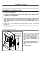
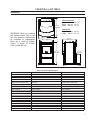
SHERWOOD INDUSTRIES IS AN ENVIRONMENTALLY RESPONSIBLE COMPANY. THIS MANUAL IS PRINTED ON RECYCLED PAPER.
PLEASE KEEP THESE INSTRUCTIONS FOR FUTURE REFERENCE
PELLET STOVE
Evolution
TECHNICAL MANUAL
����
PLEASE READ THIS ENTIRE MANUAL BEFORE INSTALLATION AND USE
OF THIS PELLET BURNING ROOM HEATER. FAILURE TO FOLLOW THESE
INSTRUCTIONS COULD RESULT IN PROPERTY DAMAGE, BODILY INJURY
OR EVEN DEATH
Contact your building or fire officials about restrictions and installation
inspection requirements in your area.
50-1574
Table of Contents
Safety Warnings & Recommendations...............................................................................................3
Installation.....................................................................................................................................6
Rating Label Location................................................................................................................6
Deciding Where to Locate your Pellet Appliance..........................................................................6
Removing Pellet Stove From Pallet.............................................................................................6
Dimensions..............................................................................................................................7
Clearances to Combustibles.......................................................................................................8
Alcove Clearances.....................................................................................................................8
Hearth Pad Pedestal Installation.................................................................................................9
Vent Termination Requirements................................................................................................10
Outside Fresh-Air Connection...................................................................................................11
Exhaust And Fresh Air Intake Locations....................................................................................11
Mobile Home Installation.........................................................................................................12
Corner Through Wall Installation..............................................................................................12
Horizontal Exhaust Through Wall Installation.............................................................................13
Through Wall With Vertical Rise and Horizontal Termination Installation- Recommended..............14
Through Concrete Wall With Vertical Rise Installations...............................................................14
Inside Vertical Installations......................................................................................................15
Outside Vertical Installations....................................................................................................15
Hearth Mount Installation........................................................................................................16
Exterior Mounted Exhaust Blower.............................................................................................17
Typical Through Wall With Exterior Blower Kit Installation - Horizontal Termination......................18
Typical Through Wall With Exterior Blower Kit Installation - Vertical Termination..........................19
Thermostat Installation............................................................................................................20
Optional Slider/Damper Installation..........................................................................................20
Slider/Damper Set-Up..............................................................................................................21
Troubleshooting............................................................................................................................22
Wiring Diagram.............................................................................................................................25
Parts List......................................................................................................................................26
Parts Diagram - Components..........................................................................................................28
Parts Diagram - Steel.....................................................................................................................29
Installation Data Sheet..................................................................................................................30
2
Safety Warnings & Recommendations
* This manual is designed for the technician in conjunction with the owner’s manual. *
Please read this entire Owner’s Manual before installing or operating your ENVIRO Pellet
Stove. Failure to follow these instructions may result in property damage, bodily injury or
even death. Any unauthorized modification of the appliance or use of replacement parts
not recommended by the manufacturer is prohibited. All national and local regulations and
European Standards shall be complied with when installing this appliance.
Caution: Do not connect to any air distribution duct or system.
Warning: Parts of the appliance, especially the external surfaces, will be hot to touch when
in operation so use due care and the fire gloves provided. Never place wood, paper, furniture,
drapes or other combustible materials within 80cm (311⁄2”) of the front of the unit, 20cm (77⁄8”) from
each side, and 10cm (4”) from the back of the unit. Do not let children or pets touch it when it is hot.
To prevent the possibility of a fire, ensure that the appliance is properly installed by adhering to the
installation instructions. An ENVIRO dealer will be happy to assist you in obtaining information with
regards to your local building codes and installation restrictions.
FIRE EXTINGUISHER AND SMOKE DETECTION: All homes with a pellet burning stove should have
at least one fire extinguisher in a central location known to all in the household. Smoke detectors should
be installed and maintained in the room containing the stove when installing and operating a pellet
burning appliance. If it sounds the alarm, correct the cause but do not deactivate. You may choose to
relocate the smoke detection devise within the room; DO NOT REMOVE THE SMOKE DETECTOR FROM
THE ROOM.
CHIMNEY OR RUN AWAY FIRE: Call local fire department. Close the draft fully. Extinguish the fire
in the burn pot liner with a cup of water and close the door. Examine the flue pipes, chimney, attic, and
roof of the house, to see if any part has become hot enough to catch fire. If necessary, spray with fire
extinguisher or water from the garden hose. IMPORTANT: Do not operate the stove again until you are
certain the chimney and its lining have not been damaged.
FUEL: This pellet stove is designed and approved to only burn wood pellet fuel with up to 3% ash content.
Dirty fuel will adversely affect the operation and performance of the unit and may void the warranty.
Check with your dealer for fuel recommendations. THE USE OF CORDWOOD IS PROHIBITED BY
LAW. When filling fuel hopper, open lid on top of unit, check hopper for foreign objects, empty the
bag into the hopper, DO NOT OVER FILL, and ensure hopper lid closes completely. DO NOT use this
appliance as an incinerator. DO NOT use unsuitable and non recommended fuels, including liquid fuels.
KEEP ASH PAN FREE OF RAW FUEL. DO NOT PLACE UNBURNED OR NEW PELLET FUEL IN ASH PAN.
A fire in the ash pan may occur.
SOOT: Operation of the stove with insufficient combustion air will result in the formation of soot which
will collect on the glass, the heat exchanger, the exhaust vent system, and may stain the outside of the
house. This is a dangerous situation and is inefficient. Frequently check your stove and adjust the slider/
damper as needed to ensure proper combustion. See: “SLIDER/DAMPER SETTING”.
3
Safety Warnings & Recommendations
CLEANING: There will be some build up of fly ash and small amounts of creosote in the exhaust. This
will vary due to the ash content of the fuel used and the operation of the stove. It is advisable to inspect
and clean the exhaust vent semi-annually or every two tons of pellets. The appliance, flue gas connector
and the chimney flue require regular cleaning. Check them for blockage prior to re-lighting after a
prolonged shut down period.
ASHES: Disposed ashes should be placed in a metal container with a tight fitting lid. The closed container
of ashes should be on a non-combustible surface, well away from all combustible materials pending final
disposal. If the ashes are disposed of by burial in soil or otherwise locally dispensed, they should be
retained in the closed container until all cinders have been thoroughly cooled.
IMPORTANT: The door and ash drawer cover must be kept closed except during ignition, refueling and
removal of residue material to prevent fume spillage.
GLASS: Do not abuse the glass by striking or slamming the door. Do not attempt to operate the stove
with broken glass. The stove uses ceramic glass. Replacement glass must be purchased from an ENVIRO
dealer. Do not attempt to open the door and clean the glass while the unit is in operation or if glass is
hot. To clean the glass, use a soft cotton cloth and mild window cleaner, gas or wood stove glass cleaner,
or take a damp paper towel and dip into the fly ash. This is a very mild abrasive and will not damage the
glass.
ELECTRICAL: The use of a surge protected power bar is recommended. The unit must be
grounded. The grounded electrical cord should be connected to a standard 220-240 volts (2.0-2.3 Amps),
50 hertz electrical outlet and also must be accessible. If this power cord should become damaged, a
replacement power cord must be purchased from the manufacturer or a qualified ENVIRO dealer. Be
careful that the electrical cord is not trapped under the appliance and that it is clear of any hot surfaces
or sharp edges. This unit’s maximum power requirement is 525 watts.
OPERATION: The door and ash drawer cover must be kept closed securely when the unit is in operation
to prevent fume spillage and for proper and safe operation of the pellet stove. Also ensure all gaskets on
the door are checked and replaced when necessary.
CAUTION: When operating during adverse weather, if the unit exhibits dramatic changes in combustion
stop using the unit immediately.
INSTALLATION: Contact your local building or fire official to obtain a permit and any information on
installation restrictions and inspection requirements for your area. All local regulations, including those
referring to national and European Standards need to be complied with when installing this appliance.
Be sure to maintain the structural integrity of your home when passing a vent through walls, ceilings, or
roofs. It is recommended that the unit be secured into its position in order to avoid any displacement. This
appliance must be installed on a floor with an adequate load bearing capacity. If an existing construction
doesn’t meet these prerequisite, suitable measures (e.g. load distributing plate) shall be taken to achieve
it.
DO NOT INSTALL A FLUE DAMPER IN THE EXHAUST VENTING SYSTEM OF THIS UNIT.
DO NOT CONNECT THIS UNIT TO A CHIMNEY FLUE SERVING ANOTHER APPLIANCE.
4
Safety Warnings & Recommendations
FRESH AIR: Outside Fresh Air connection is optional. Fresh Air must be connected to all units installed
in “Air Tight Homes” or where required by local codes.
Consider all large air moving devices when installing your unit and provide room air accordingly. NOTE:
Extractor fans when operating in the same room or space as the appliance, may cause problems. Limited
air for combustion may result in poor performance, smoking and other side effects of poor combustion.
The stove’s exhaust system works with negative combustion chamber pressure and a slightly positive
chimney pressure. It is very important to ensure that the exhaust system be sealed and airtight. The ash
pan and viewing door must be locked securely for proper and safe operation of the pellet stove.
Do not burn with insufficient combustion air. A periodic check is recommended to ensure proper
combustion air is admitted to the combustion chamber. Setting the proper combustion air is achieved by
adjusting the slider damper located on the left side of the stove.
Minor soot or creosote may accumulate when the stove is operated under incorrect conditions such as an
extremely rich burn (black tipped, lazy orange flames).
If you have any questions with regards to your stove or the above-mentioned information, please feel
free to contact your local dealer for further clarification and comments.
SINCE SHERWOOD INDUSTRIES LTD. HAS NO CONTROL OVER THE INSTALLATION OF
YOUR STOVE, SHERWOOD INDUSTRIES LTD. GRANTS NO WARRANTY IMPLIED OR STATED
FOR THE INSTALLATION OR MAINTENANCE OF YOUR STOVE. THEREFORE, SHERWOOD
INDUSTRIES LTD. ASSUMES NO RESPONSIBILITY FOR ANY CONSEQUENTIAL DAMAGE(S).
SAVE THIS INSTRUCTION MANUAL FOR FUTURE REFERENCE
5
Installation
RATING LABEL LOCATION:
The rating label is located on the inside of the ash pan cover.
DECIDING WHERE TO LOCATE YOUR PELLET APPLIANCE:
1. Check clearances to combustibles.
2. Do not obtain combustion air from an attic, garage or any unventilated space. Combustion air may
be obtained from a ventilated crawlspace.
3. Do not install the stove in a bedroom.
4. You can vent the stove through an exterior wall behind the unit or connect it to an existing masonry
or metal chimney (must be lined if the chimney is over 15 cm (6”) diameter, or over 180 cm² (28
inches²) cross sectional area). An interior vent can be used with approved pipe passing through the
ceiling and roof.
5. Locate the stove in a large and open room that is centrally located in the house. This will optimize
heat circulation.
6. The power cord is 2.43 m (8 feet) long and may require a grounded extension cord to reach the
nearest electrical outlet.
REMOVING PELLET STOVE FROM PALLET:
Remove the two (2)
wood screws (one
on either side of the
unit) to remove the
unit from the pallet.
1. Remove the right and left hand cabinet
sides by loosening the three (3) T-20 Torx
screws on the back of the each panel.
2. Remove the one (1) screw located on the
front of the cabinet side, behind the top
louvers and one (1) screw behind the ash
door.
3. Remove the two (2) wood screws that are
holding the bottom of the stove to the
pallet.
4. Close the side panels.
Figure 1: Screws to take out to remove stove from pallet.
6
Installation
DIMENSIONS:
27 7/8"
(708 mm)
Unit Dimensions
Height: 840 mm (33 1/16”)
Width: 565 mm (22 1⁄4”)
Depth: 539 mm (21 1⁄4”)
Hearth Pad:
Width: 619 mm (24 3⁄8”)
Depth: 708 mm (27 7⁄8”)
IMPORTANT: When not installing
the optional Hearth Pad on the
unit, the minimum requirements
for protection on combustibles
floors are a width of 620mm
(243⁄8”) & depth of 670mm
(263⁄8”) under the unit.
24 3/8" (619 mm)
21 1/4"
(539 mm)
22 1/4" (565 mm)
5 13/16"
(147 mm)
33 1/16"
(840 mm)
26 3/8" (670 mm)
Figure 1: Dimensions of Evolution.
Table 1: Evolution Specifications.
Classification
Testing Standard
Description
Class I IP-20
EN14785:2006/EN13240:2001/A2:2004
Residential Wood Pellet Heater
Voltage
Current
Frequency
220 - 240 V
2.0 - 2.3 Amps
50 Hz
Maximum Power Requirement
Fuel type
Calorific value of Pellet used
525W (1793 BTU/hr)
wood pellets - 6mm (1⁄4”) dia.
≥ 5.10 kWh/kg (≥ 7900 BTU/lb)
Maximum Flue Gas Temperature
Mean Flue Gas Temperature
Mean Flue Gas Temperature (Reduced)
200°C (392°F)
192°C (378°F)
143°C (289°F)
Nominal Heat Output
CO emissions from Combustion
Energy Efficiency
7.6 KWh (25932 BTU)
0.032%
84%
Reduced Heat Output
CO emissions from Combustion (Reduced Output)
Energy Efficiency (Reduced Output)
3.2 KWh (10919 BTU)
0.045%
75%
CO2 at Nominal Output
Nominal Fuel Consumption Rate
Unit with Full Hopper
8.35%
1.78 Kg/hr (3.95 lb/hr)*
~ 140kg (310lb)
CO2 at Reduced Output
Fuel Consumption Rate (Reduced Output)
Hopper Capacity
3.45%
0.83 Kg/hr (1.85 lb/hr)*
~ 40kg (90lb)
*Note: Consumption will vary with the type of fuel used.
7
Installation
CLEARANCES TO COMBUSTIBLES:
This unit can be installed on a combustible floor when installed with the optional hearth pad part 50-1568
(for example linoleum, hardwood flooring). If this unit is to be installed onto a carpeted surface, a hearth
pad must be used for stability.
Back Wall
4" (10cm)
4"
(10cm)
Side Wall
l
al
tW
n
ce
ja
Ad
77/8"
(20cm)
These dimensions are minimum clearances
but it is recommended that you ensure
sufficient room for servicing, routine cleaning
and maintenance.
Side wall to unit
Back wall to unit
Corner to unit
In Front of unit
200mm
100mm
100mm
800mm
(77⁄8 inches)
(4 inches)
(4 inches)
(311⁄2” inches)
Figure 3: Evolution Clearance to Combustibles.
ALCOVE CLEARANCES:
48"
(122cm)
This unit may be installed in an alcove.
Maintain these clearances to combustibles.
Minimum Alcove width 1220mm
Minimum Alcove height 1220mm
Maximum Alcove depth 1220mm
(48 inches)
(48 inches)
(48 inches)
48"
(122cm)
Install vent at clearances specified by
the vent manufacturer.
48"
(122cm)
Figure 4: Evolution Minimum Alcove Size.
8
Installation
HEARTH PAD PEDESTAL INSTALLATION:
This unit can be installed on a combustible floor (e.g. linoleum, hardwood flooring) when the Optional
Hearth Pad is installed. If this unit is to be installed onto a carpeted surface, a solid pad must be used
underneath the Optional Hearth Pad for stability.
Carefully place the the pellet appliance on its back, on the pallet (allow the exhaust tube to fit thru an
opening in the pallet). Align the holes in the hearth pad and the unit and install the four (4) screws
provided. Stand the unit back up. Adjust the leveling legs to below the Hearth Pad, to support the weight
of the unit.
When moving the unit - be careful not to damage the floor or the Hearth Pad.
��������
���� ��
Figure 5: Installing Hearth Pad Pedestal onto Evolution.
9
Installation
VENT TERMINATION REQUIREMENTS:
IT IS RECOMMENDED THAT YOUR PELLET STOVE BE INSTALLED BY AN AUTHORIZED DEALER/INSTALLER.
Table 2: Use in conjunction with Figure 6 for allowable exterior vent termination locations.
Letter
Minimum Clearance
A
61cm (24 in)
B
C
D
Description
Above grass, top of plants, wood, or any other combustible materials.
122 cm (48 in)
Beside/below any door or window that may be opened. (46 cm (18”) if outside
fresh air install.)
30 cm (12 in)
Above any door or window that may be opened. (23 cm (9”) if outside fresh air
install.)
61cm (24 in)
To any adjacent building, fences and protruding parts of the structure.
E
61cm (24 in)
Below any eave or roof overhang
F
30 cm (12 in)
To outside corner.
G
30 cm (12 in)
To inside corner, combustible wall (vertical and horizontal terminations).
H
91 cm (3 ft) within a height
of 4.5 m (15 ft) above the
meter/regulator assembly
I
91 cm (3 ft)
J
To each side of center line extended above natural gas or propane meter/
regulator assembly or mechanical vent.
From any forced air intake of other appliance
30 cm (12 in)
Clearance to non-mechanical air supply inlet to building, or the combustion air
inlet to any appliance.
K
61cm (24 in)
Clearance above roof line for vertical terminations.
L
2.13 m (7 ft)
Clearance above paved sidewalk or paved driveway located on public property.
1. Do not terminate the
vent in any enclosed or
semi-enclosed areas such
as a carport, garage,
attic, crawlspace, narrow
walkway, closely fenced
area, under a sundeck
or porch, or any location
that can build up a
concentration of fumes
such as stairwells, covered
breezeway, etc.
G
K
E
D
F
B
Opens
G
Opens
B
A
Termination Cap
Air Supply Inlet
G
C
I
G Gas Meter
Opens
Restriction Zone
L
H
(Termination not allowed)
Figure 6: Use in conjunction with Table 2 for allowable exterior vent termination
locations.
2. Vent surfaces can become
hot enough to cause burns if touched by children. Non-combustible shielding or guards may be required.
3. Termination must exhaust above the inlet elevation. It is recommended that at least five feet of vertical pipe be
installed outside when the appliance is vented directly through a wall, to create some natural draft to prevent the
possibility of smoke or odor during appliance shut down or power failure. This will keep exhaust from causing a
nuisance or hazard from exposing people or shrubs to high temperatures. In any case, the safest and preferred
venting method is to extend the vent through the roof vertically.
4. Distance from the bottom of the termination and grade is 30 cm (12 in) minimum. This is conditional upon the
plants and nature of grade surface. The exhaust gases are hot enough to ignite grass, plants and shrubs located
in the vicinity of termination. The grade surface must not be lawn.
5. If the unit is incorrectly vented or the air to fuel mixture is out of balance, a slight discoloration of the exterior
of the house might occur. Since these factors are beyond the control of Sherwood Industries Ltd, we grant no
guarantee against such incidents.
NOTE: Venting terminals shall not be recessed into walls or siding.
10
Installation
OUTSIDE FRESH-AIR CONNECTION:
This Heater must have adequate air for proper combustion in the room that it is installed.
A Fresh-air intake is strongly recommended for all
installations. Failure to install intake air may result in improper
combustion as well as the unit smoking during power failures.
�������
����
The inlet to the intake must be below and a minimum of 305mm
(12”) away from the unit exhaust outlet.
Outside fresh air is mandatory when installing this unit
in airtight homes and mobile homes.
When connecting to an outside fresh air source, do not use
plastic or combustible pipe. A 50mm minimum (2”) ID (inside
diameter) steel, aluminum or copper pipe should be used. It is
recommended, when you are installing a fresh air system, to
keep the number of bends in the pipe to a minimum.
�� ��
��� ���
��������
�����
Figure 7: Outside Air Connection.
EXHAUST AND FRESH AIR INTAKE LOCATIONS:
The Exhaust Starter Tube can be installed 2 ways:
Angled towards the center - Use a Tee with vertical for a “centered” vertical installation.
Straight out the back - For horizontal thru the wall and up installation
EXHAUST Location:
Base of unit to center of flue
Center of unit to center of flue
FRESH AIR INTAKE.
Base of unit to center of intake
Center of unit to center of intake
278mm (1015/16”)
35mm (13⁄8”)
227mm (815/16”)
105mm (41⁄8”)
10 15/16"
(278 mm)
8 15/16"
(227 mm)
4 1/8"
(105 mm)
1 3/8"
(35 mm)
Figure 8: Evolution Inlet and Outlet Location.
IMPORTANT: This unit must be connectect to an 80mm stainless steel vent pipe exhausting outside
the building.
11
Installation
MOBILE HOME INSTALLATION:
● Secure the heater to the floor using the
two holes in the pedestal.
● Ensure the unit is electrically
grounded to the chassis of your home
(permanently).
● Do not install in a room people sleep in.
● Outside fresh air is mandatory. Secure
outside air connections directly to fresh
air intake pipe and secure with three
(3) screws evenly spaced.
CAUTION: THE STRUCTURAL
INTEGRITY OF THE
MANUFACTURED HOME FLOOR,
WALL AND CEILING/ROOF MUST
BE MAINTAINED.
ENVIRO EF5
Optional
Hearth Pad
Flooring
Steel
Frame
1/4” Lag Bolts
Securely Fastened
Ground Wire Directly
to Metal Chassis
Figure 9: Mobile home installation.
CORNER THROUGH WALL INSTALLATION:
Fresh Air Intake
4" (10 cm)
Wall thimble
manufactured
by pellet vent
manufacturer.
4"
(10 cm)
Figure 10: Corner Installation.
12
Installation
HORIZONTAL EXHAUST THROUGH WALL INSTALLATION:
Vent installation: install vent at clearances specified by the vent manufacturer.
A chimney connector shall not pass through an attic or roof space, closet or similar concealed spaces,
or a floor, or ceiling. Where passage through a wall or partition of combustible construction is desired,
the installation must conform with all local regulations, including those referring to regional, national or
European Standards. Use 80mm stainless steel vent pipe to exhaust the unit to the outside.
1. Choose a location for your stove that meets the requirements stated in this manual and allows
installation with the least amount of interference to house framing, plumbing, wiring, etc.
2. Install a non-combustible hearth pad (where necessary).
3. Place the appliance 375 mm (15”) away from the wall. If the stove is to be set on a hearth pad, set
the unit on it.
4. Locate the center of the exhaust pipe on the stove. Extend that line to the wall. Once you have located
the center point on the wall, refer to pellet vent manufacturer installation instructions for correct hole
size and clearance to combustibles.
5. Install the wall thimble as per the instructions written on the thimble. Maintain an effective vapour
barrier in accordance with local building codes.
6. Install a length of 80mm (3”) vent pipe into the wall thimble. The pipe should install easily into the
thimble.
7. Install the fresh air intake (see OUTSIDE FRESH AIR CONNECTION).
8. Connect the exhaust vent pipe to the exhaust pipe on the stove. Seal the connection with high
temperature silicone.
9. Push the stove straight back, leaving a minimum of 100mm (4”) clearance from the back of the stove
to the wall. Seal the vent pipe to the thimble with high temperature silicone.
10. The pipe must extend at least 30 cm (12”) away from the building. If necessary, bring another
length of pipe to the outside of the home to connect to the first section. Do not forget to place high
temperature silicone around the pipe that passes through the thimble.
11. Install a vertical pipe, or if all requirements for direct venting are met, install vent termination. The
stainless steel cap termination manufactured by the vent manufacturer is recommended. However,
when the vent terminates several feet above
ground level and there are no trees, plants,
etc. within several feet, a 45° elbow can be
used as termination. The elbow must be
���� �������
turned down to prevent rain from entering.
NOTE:
• It is recommended that horizontal through wall
installations have 3 to 5 feet (91 to 152 cm)
of vertical pipe in the system to help naturally
draft the unit in the event of extreme weather
or a power outage.
• Some horizontal through wall installations may
require a “T” and 3 to 5 feet (91 to 152 cm) of
vertical pipe outside the building to help draft
the unit. This may be required if a proper burn
cannot be maintained, after the stove has
been tested and the airflow set. This is due
to the back pressure in the exhaust caused by
airflow around the structure.
�������� ���� �������
����������� ���
���� �������
���� ����
�� �
Figure 11: Straight through wall Installation.
13
Installation
• Follow vent manufacturer’s guidelines for installation of venting. High temperature sealant must be
used when connecting the vent pipe to the unit’s starter pipe. Improper seals at the vent joints may
cause combustion byproducts to leak into the room where installed - seal as required..
THROUGH WALL WITH VERTICAL RISE AND HORIZONTAL TERMINATION INSTALLATION- RECOMMENDED:
���� �������
����������� ���
�������� ���� �������
A 45° down elbow with a rodent screen
may be used in place of the termination
cap (or stainless steel termination hood).
�������� �������
�� ���� ����
���� �������
�� �
Figure 12: Venting horizontally with rise.
THROUGH CONCRETE WALL WITH VERTICAL RISE INSTALLATIONS:
Horizontal frame
for thimble
A 45° down elbow with a rodent screen
may be used in place of the termination cap
(or stainless steel termination hood).
Installation to use if there is a concrete or
retaining wall in line with exhaust vent on
pellet stove.
Termination cap
Wall thimble
90o elbow
Wall framing
Vertical section
of vent pipe
The termination must be 305mm (12”) from
the outside wall and 305mm (12”) above
the ground.
Concrete Wall
EF 5
Clean out tee
Figure 13: Venting with concrete wall behind unit .
14
Installation
INSIDE VERTICAL INSTALLATIONS:
1. Choose a stove location that is ideal. See the section “DECIDING WHERE
TO
LOCATE
YOUR
PELLET APPLIANCE.”
2. Place a non-combustible hearth pad where necessary.
3. Place the unit on the hearth pad (if
installed on a carpeted surface) and
space the unit in a manner so when
the pellet vent is installed vertically,
it will be 100mm (4”) away from a
combustible wall.
4. Locate the center of the fresh air
intake pipe on the unit. Match that
center with the same point on the
wall and cut a hole about 40mm
(15⁄8”) in diameter.
Rain Cap (ensure cap
is at least 3ft (91cm)
above the roof at the
lowest point)
2 ft
(61 cm)
Roof Flashing
Roof Rafter
Fire Stop with
Support Collar
Ceiling Joist
5. Install the fresh air intake pipe.
6. Install the tee with clean out.
7. Install the pellet vent upward
from there. When you reach the
ceiling, make sure that the vent
goes through the ceiling fire stop.
Maintain a 100mm (4”) distance
to combustibles and keep attic
insulation away from the vent pipe.
Maintain an effective vapor barrier.
8. Finally, extend the pellet vent to go
through the roof flashing.
9. Ensure that the rain cap is
approximately 900 mm (36”) above
the roof.
Vertical Vent Pipe
Clean Out Tee with
Pipe Adapter
EF 5
NOTE: All vent sections must
maintain 3 inches (7.6 cm)
clearances to combustibles.
Figure 14: Inside Vertical Installation.
OUTSIDE VERTICAL INSTALLATIONS:
To accomplish a outside vertical pipe installation, follow steps 1 through 5 in the “INSIDE VERTICAL INSTALLATIONS
- FREESTANDING” section and then finish it by performing the following (refer to Figure 15).
1. Install a tee with clean out on the outside of the house.
2. Install vent pipe upward from the tee. Make sure that you install support brackets to keep the vent
straight and secure.
3. Install ceiling thimble and secure the flashing as you go through the roof.
4. Ensure that the rain cap is approximately 900 mm (36”) above the roof.
15
Installation
Rain cap
Flashing
24"
(61 cm)
4"
(10cm)
3" (7.5 cm)
Clearance
Support
bracket
Tee with
cleanout
Type "L"
vent
Fresh air
intake
Figure 15: Outside Vertical Installation.
HEARTH MOUNT INSTALLATION:
Rain Cap
Seal Plate
Existing Masonary
Flue
Vent Pipe (single
wall stainless flex
pipe or PL vent)
Flexible Vent Connector
(Use this 5 ft section of
pipe to vent past
fireplace damper or
smoke shelf)
Fireplace Damper
Location
Clean Out Tee
Existing Fireplace
EF 5
Figure 16: Hearth mount installation.
16
Refer to Figures 16.
1. Lock fireplace damper in the open position.
2. Install a positive flue connector at the
fireplace dampers.
3. Connect a tee or a 90° elbow to the exhaust
pipe.
4. Install flexible stainless steel liner or listed
pellet vent to the top of the chimney.
Installation
EXTERIOR MOUNTED EXHAUST BLOWER:
The Evolution can be equipped with an externally mounted exhaust blower. This optional kit includes all
components necessary to install the exhaust blower on any vertical wall surface.
Choose a location for your stove that meets the requirements
stated in your manual and allows installation with the least
amount of interference with house framing, plumbing,
wiring, etc.
Included in the Exterior Mounted Exhaust Blower Kit are:
1 - Exhaust blower housing box.
1 - Blower cover plate.
1 - Hardware bag
Figure 17: Exterior Blower Kit.
1. Remove the left hand cabinet side by removing the two
(2) screws down the front. Loosen the three screws on the
back of the cabinet side and remove panel.
2. Loosen the six (6) screws that hold the back grill in place.
Lift the back grill off the screws.
3. Disconnect the Exhaust blower wires from the wire
harness. Remove the exhaust blower motor from the
housing; six (6) screws. Cover hole in housing with cover
plate provided (see Figure 18).
Figure 18: Exterior Blower Kit.
4. Remove the cover from the exhaust blower housing box.
5. Install the exhaust blower housing box into the pipe placed
through the wall thimble, seal with high temperature
silicone. Fasten the box to the wall with (4) four screws,
seal edges of box to wall with clear silicone.
6. Drill a hole through the wall thimble plate for the electrical
wires. Pass the armored cable through the wall thimble.
Use the strain relief provided. Do not pass cable
through vent hole.
7. Install the Exhaust Blower motor into the external exhaust
blower housing box. Make the electrical connections to the
wire harness and exhaust blower.
8. Replace the cover on the Exhaust Box and the back grill of
the stove and ensure the screws are tightened down.
Figure 19: Exterior Blower Kit cut-through.
9. Install vertical pipe as instructed in appropriate section.
17
Installation
TYPICAL THROUGH WALL WITH EXTERIOR BLOWER KIT INSTALLATION - HORIZONTAL TERMINATION:
EF 5
90° Elbow
45°Elbow with Rodent
screen or stainless
steel termination hood
2ft Riser
Pipe Adaptor
Electrical Cable
Exterior Blower
and Housing
Figure 20: Through Wall Installation with Exterior Blower Kit.
NOTE:
Ensure that all interior vent connections are sealed by placing a small bead of high temperature silicone
around each chimney connection.
Also ensure that all vertical vent sections are properly supported and that all clearances to combustibles
are maintained in accordance with the vent manufacturer’s specifications.
Wall Strap
To supply power
to the exhaust
Figure 21: Through Wall Installation with Exterior Blower Kit; Side View.
Install an amour coated electrical cable from the exhaust blower housing, through the wall thimble plate
and attach to the pre drilled hole in the left hand rear hopper pillar. Hook up to wires from the exhaust
blower wiring harness.
All electrical connections must be in accordance to local code requirements
18
Installation
TYPICAL THROUGH WALL WITH EXTERIOR BLOWER KIT INSTALLATION - VERTICAL TERMINATION:
Follow the previous pages for through wall installations. Ensure that vent pipe is properly secured to wall
using wall straps. Maintain clearances to combustibles on vent pipe as well as unit.
Roof Sheathing
Rain Cap
Roof Flashing
Roof Rafters
Ceiling Joists
Vent Pipe
Exterior Wall
Sheathing
Outside Vent
Termination
EF5
Figure 22: Through Wall Installation with Exterior Blower Kit; Vertical Termination.
19
Installation
THERMOSTAT INSTALLATION:
1. Install the wall thermostat (12 or 24 Volt rated) in a location that is not to close too the unit but will
effectively heat the desired area.
2. Connect the Thermostat or Timer using an 2 x 18 gauge wire from the unit to the thermostat.
If the unit has been placed in the HI / LOW mode, the unit
will be taken to a low or idle setting when the thermostat
is not calling for heat. When the thermostat calls for
heat, the unit will go to the setting that is displayed on
the control board Heat Indicator. If the heat in the room
becomes to great, the high limit switch may turn the
stove off and the switch will have to be manually reset.
To reset the high limit switch, remove the right cabinet
side. The switch is found behind the control panel. Avoid
setting off the high limit switch.
Remove jumper
wire and install
thermostat wires here.
Figure 23: Thermostat wire placement.
OPTIONAL SLIDER/DAMPER INSTALLATION:
NOTE: NOT APPLICABLE FOR GERMANY AND
NEW ZEALAND
If you wish to adjust the slider damper externally (NOT
REQUIRED), please follow the instructions below.
Slider damper
rod and knob
7
/16" Nut
7
/16" Clinching Nut
Slider damper plate
Figure 24: Slider/Damper Assembly.
Slider/
Damper
Knob
Figure 25: Slider/Damper Knob.
20
1. To install the OPTIONAL slider damper rod, remove the left cabinet
side and locate the slider damper plate. Install the 7/16” (11mm)
nut onto the slider damper rod, thread all the way to the end of
the threads on rod.
2. Slide rod through the hole in the slider damper plate and install
the 7/16” (11mm) clinching nut onto the rod and tighten completely
onto the slider damper plate.
3. Re-install the cabinet side. Install the black knob on the end of the
rod. Check slider damper for smooth operation.
Installation
SLIDER/DAMPER SET-UP:
This is used to regulate the airflow through the pellet stove. The slider damper should be set
by a trained technician using magnehelic.
The slider damper is located behind the left side panel. To open the left side panel, undo the one screw
located in the upper front corner of the cabinet side between the louvers. Also loosen three screws down
the back of the side panel.
The combustion exhaust blower is a
variable speed blower controlled by the
heat output button. This blower will
decrease the vacuum pressure inside
the stove and as the heat output button
is turned down. The vacuum pressure
inside the firebox will increase as the
combustion exhaust blower increases
in speed (higher heat output setting).
Air Intake Box
Exhaust Channel
Slider Damper
Exhaust Blower
If the fire should happen to go out
Figure 26: Slider/Damper Plate in Unit.
and the heat output indicator has been
set on the lowest setting, the Slider Damper should be
pushed in slightly, decreasing the air in the firebox.
If, after long periods of burning, the fire builds up and
overflows the burn pot or there is a build up of clinkers,
this would be a sign that the pellet quality is poor, this
requires more primary air, the slider damper must be
pulled out to compensate. Pulling the slider damper out
gives the fire more air.
The easiest way to make sure that an efficient flame is
achieved is to understand the characteristics of the fire.
• A tall, lazy flame with dark orange tips requires more
air – Open slider (pull out) slightly.
• A short, brisk flame, like a blowtorch, has too much air
Figure 27: Efficient Flame.
– Close slider (push in) slightly.
• If the flame is in the middle of these two characteristics with a bright yellow/orange, active flame
with no black tips then the air is set for proper operation (see Figure 27).
SPECIAL NOTES:
Pellet quality is a major factor in how the Pellet stove will operate. If the pellets have a high moisture
content or ash content the fire will be less efficient and has a higher possibility of the fire building up and
creating clinkers (hard ash build-up).
IMPORTANT: Taking a reading of vacuum pressure inside the firebox with a magnehelic gauge should be
used to set the slider for best combustion. The slider damper should be set only on a hot stove (operating
for thirty (30) minutes or more) by using a Magnahelic Pressure Gauge to measuring the pressure in the
firebox. The best settings are a reading of approximately 27.4 - 29.9 Pa (0.11 - 0.12 inches of
water column) on the high fire setting. Some fuels may require higher or lower settings. The
reading can be taken from the 3 mm (1⁄8”) hole located on the front of the unit below the ash shelf.
21
Troubleshooting
DO NOT:
● Service the stove with wet hands. The stove is an electrical appliance, which may pose a shock hazard
if handled improperly. Only qualified technicians should deal with possible internal electrical failures.
● Do not remove from the firebox any screws without penetrating oil lubrication.
WHAT TO DO IF:
1. The stove will not start.
2. The stove will not operate when hot.
3. The exhaust blower will not function normally.
4. Light # 2 on Heat output bar flashing.
5. Auger light flashes but auger motor does not turn at all
6. The 93°C (200°F) high limit temperature sensor has tripped.
7. The convection blower will not function normally.
8. Igniter- the pellets will not light.
9. Control settings (Heat Level) has no effect on the fire.
10. The stove keeps going out.
*NOTE: All troubleshooting procedures should be carried out by qualified technicians or
installers.
1. The stove will not start.
üMake sure the stove is plugged in and the wall outlet is supplying power..
üIf the Control Board has been placed in the AUTO /OFF thermostat mode, then turn the thermostat up
or timer ON to call for heat.
üEnsure the burn pot liner is correctly placed in the burn pot
üCheck the Heat Level Indicator. - If the # 2 light is flashing (see the # 2 light is flashing)
üCheck the fuse on the circuit board.
üIf the unit still does not start, contact your local service dealer for service.
2. The stove will not operate when hot.
üCheck the Heat Level Indicator if a fire is not detected, or if the fire has gone out the #3 light will
flash because the Exhaust Temperature Sensor’s contacts have opened.
üCheck the hopper for fuel.
üIncorrect air damper setting. - Excessive air may consume the fire too quickly before the next drop of
fuel, leaving completely unburned fuel in the burn pot liner. - Insufficient air will cause build up, further
restricting the air flow through the Burn Pot Liner. This in turn will cause the fuel to burn cold and very
slowly. Fuel may build up and smother the fire. In this case clean the burn pot. (NOTE: unit may
require a change to the vent system or installation of fresh air to correct Air to Fuel ratio
problems).
üCombustion Blower failure. - The Combustion Blower is not turning fast enough to generate the proper
vacuum in the fire box. Visual Check – is the blower motor turning.
üCheck the Exhaust Blower voltage across the blower wires (>=220V on #5 setting and >= 165V on
#1 setting). – Replace the Circuit Board if the Voltage reading is less than 165 V. with a line voltage
>220 V AC.
üCheck Vacuum levels in the exhaust channel by bypassing the Vacuum Switch, then remove the Vacuum
hose from Vacuum Switch. Check exhaust vacuum readings by placing the open end of the Vacuum
Hose on a Magnahelic Gauge (readings must be above 24.9 Pa (.10” W.C.) on low fire).
If the motor fails to reach a 24.9 Pa (.10” W.C.) readings, then replace the Combustion Blower.
22
Troubleshooting
üPoor Quality Fuel – Insufficient energy in the fuel to produce enough heat to keep the stove burning
or operational.
üExhaust Temperature Sensor failure. – Bypass sensor located on Exhaust Blower if stove now operates
properly, the unit may require cleaning or a new sensor. Contact your local dealer for service.
üCheck the fuse on the circuit board.
3. The exhaust motor will not function normally.
üOpen the left side access panel; check all connections against the wiring diagram.
üSee “2. The stove will not operate when hot.” section.
4. Light # 2 on Heat output bar flashing
(The Vacuum Switch contacts have opened for more than 15 sec.)
üPinch, break or blockage in Vacuum Hose - Check hose for pinch points or damage, replace or re-route
as required. Blow out Vacuum Hose
üBlocked Hose Barb on Exhaust Channel - Use a paper clip to clean out Hose Barb or remove the Vacuum
Hose from the Vacuum Switch and blow into the hose to remove blockage.
üBlocked exhaust / venting system - Have stove and venting cleaned and inspected.
üSevere negative pressure in area where unit is installed - Check the operation by opening a window,
does this solve the problem? If it does, install fresh air intake to unit or room. Venting system may
require vertical section to move termination into a low pressure zone.
üVacuum Switch failure - Bypass the vacuum switch, if this corrects the problem check for above
problems before replacing the Vacuum Switch.
üDamage to gray wires between Circuit Board and Vacuum Switch - Inspect wires and connectors
üCombustion Blower failure - The Combustion Blower is not turning fast enough to generate the proper
vacuum in the Exhaust Channel. Visual Check; is the blower motor turning? Check the Exhaust Blower
voltage across the blower wires (>=220V on #5 setting and >= 165V on #1 setting). – Replace the
Circuit Board if the Voltage reading is less than 165 V. with a line voltage >220 V AC.
üCheck Vacuum levels in the exhaust channel by bypassing the vacuum switch, then remove the Vacuum
hose from Vacuum Switch. Check exhaust vacuum readings by placing the open end of the Vacuum
Hose on a Magnahelic Gauge. (readings must be above 24.9 Pa (.10” W.C.) on low fire).
If the motor fails to reach a 24.9 Pa (.10” W.C.) readings, then replace the Combustion Blower
To reset Circuit Board after a trouble code - push the ON/OFF button
5. Auger light flashes but auger motor does not turn at all.
üIf the Auger gear box does not turn but the motor’s armature does try to spin then the auger is jammed.
– Try to break apart jam by poking at the jam through the drop tube. If this fails then empty the hopper
and remove the Auger Cover **Remember to re-seal the cover after installation**
üCheck the fuse on the circuit board.
6. The 93°C (200°F) high limit temperature sensor has tripped.
üReset sensor and determine cause – was it Convection Blower failure or 71°C (160°F) Temperature
Sensor failure? Bypass the 71°C (160°F) sensor, does the Convection blower come on high if not
replace the blower? If yes, replace sensor (located on the left side of the firewall).
üCheck the fuse on the circuit board.
23
Troubleshooting
7. The convection blower will not function normally.
üClean all grill openings at the back and below unit .
üPress the fan button; does the fan come on? Press again to verify that the blower turns on; if, not
contact your local dealer for service.
8. Ignitor- the pellets will not light.
üEverything else in the stove operates but the ignitor will not light the pellets.
üMake sure the burn pot liner is up tight and square to the ignitor tube by pushing the burn pot back
against the ignitor tube.
üCheck to see if the exhaust blower is operating. If not, contact your local dealer for service.
üCheck the fuse on the circuit board.
NOTE: The ignitor should be bright orange in color. If not replace the ignitor.
9. Control settings (Heat Level) has no effect on the fire.
üNOTE: If the system light is flashing the Control Board has complete control of the unit. When the units
system light becomes solid then control of the unit is given back to the operator.
üIf there is no control of the Heat Level button make sure the Thermostat/Timer is calling for heat.
üCall your local dealer for service.
10. The stove keeps going out.
If the stove goes out and leaves fresh unburned pellets or cigarette-like ashes in the burn pot liner, the
fire is going out before the stove shuts off.
üCheck to see that the Slider / Damper is in the correct position.
üTurn the Heat Level up slightly (poor quality pellets will require slightly higher settings).
üSet the auger trim till the #1 and #5 lights are illuminated.
If the stove goes out and there are partially burned pellets left in the burn pot liner, the stove has shut
down due to a lack of air, exhaust temperature, or power failure.
üAdjust the Slider / Damper.
üCheck to see if the stove needs a more complete cleaning.
üTurn the Heat Level up slightly (poor quality pellets will require slightly higher settings).
üDid the power go out?
üContact your local Dealer for service.
24
Wiring Diagram
Armor Cable Supplied
Optional Exterior
Exhaust Blower
Grey
Grey
Black
Combustion
Blower
Vacuum
Switch
White
White
Blue
Brown
Exhaust
Temperature
Sensor
Power
Cord
Brown
Ground
Thermostat
5 Amp
Fuse
Black
White
Orange
Orange
Purple
Blue
Yellow
Red
Grey
Grey
Brown
Brown
Red
Red
115V
White
220V
Blue
115V
Black
220V
Brown
Connect
Thermostat
Here
Hot
Red
White
Black
Black
Common
Ignitor
Purple
White
Yellow
White
Orange
Orange
Convection
Blower
Auger
Motor
High Limit
Temperature
Sensor
25
Parts List
Reference #
1
2
Part #
120°F (49°C) Ceramic Fan Temperature Sensor
EC-001
Window Channel Tape - 1.8m (72”)
EC-058
Auger Motor - 220V
EF-001-220V
Combustion Blower Mounting Gasket
EF-011
Combustion Blower Housing Gasket (Circular)
EF-012
3
High Limit Temp Sensor 200°F (93°C) Manual Reset
4
Vacuum Switch - 220V
EF-016
EF-017-220V
Silicone Hose
EF-018
Aluminum Hose Barb
EF-019
Shoulder Bolt, Hardened Bush & Nut (SET of 2)
EF-124
Ash Pan Latch
EF-178
Pedestal & Ash Pan Gasket - 10’ (305 cm)
EF-208
Both Side Panels With Hopper Lid - Stainless Steel
EF5-101
6
Burn Pot
EF5-128
7
Ash Pan
EF5-129
8
Ash Pan Cover
EF5-131
9
Glass Retainer Set
EF5-133
10
Door Handle
EF5-134
11
Door Hinge Bracket
EF5-135
12
Door Only - Painted
EF5-136
13
Heat Exchange Rod
EF5-138
14
Hopper Lid - Painted
EF5-140
14
Hopper Lid - Stainless Steel
EF5-141
15
External Exhaust Back
EF5-143
External Exhaust Box
EF5-144
16
External Exhaust Bottom
EF5-145
17
NZ Power Cord - 220V
20-011
17
IEC Power Cord - 220V
20-013
18
Door Assembly Complete
20-014
Hardened Bushing
20-020
19
Glass With Gasket (356 mm x 356 mm)
20-023
20
Cabinet Side Left - Stainless Steel
20-029
20
Cabinet Side Left - Painted
20-031
21
Cabinet Side Right - Stainless Steel
20-030
21
Cabinet Side Right - Painted
20-032
Cast Top
20-038
22
Control Panel Door
20-040
22
Control Panel Door - Stainless Steel
50-684
5
26
Description
Parts List
Reference #
Description
Part #
Door Gasket - 7ft (213 m)
50-088
23
Top Louver Set - Nickel
50-097
24
Ash Shelf Louver
50-162
Slider Damper Rod & Knob
50-293
Top Glass Retainer
50-294
Control Panel Touch Latch
50-323
Circuit Board Wire Harness
50-332
Hopper Guard
50-333
25
Convection Blower - 220V
50-513
26
Convection Blower Mount & Hardware
50-585
27
External Exhaust Kit (80mm Pipe)
50-492
28
400 Watt Ignitor - 220V
50-646
Auger Mounting Hardware
50-689
IEC Power Cord Inlet Socket
50-713
Circuit Board 5 Amp Fuse - 220V (Pair)
50-834
Auger Plate With Bushing
50-899
Exhaust Blower Assembly - 220V
50-900
Auger Motor Mount
50-910
31
Burn Pot Liner - High Ash
50-961
32
Auger with paddles
50-1085
33
Back Grill
50-1222
Burnpot Scrapper Tool
50-1254
End Cap with 1⁄2” Bushing
50-1255
34
Levelling Legs (Set of 4)
50-1342
35
Hopper Lid Hinge (4 Piece Set)
50-1376
36
Firebox Brick Liner - Square Drop Tube
50-1411
37
Firebox Panel Set With Inslulation - Square Drop Tube
50-1474
38
Control Panel and Decal
50-1475
39
Control Panel Decal
50-1476
40
Circuit Board with Thermostat Switch 3sec On Time 230V
50-1522
Gloves
50-1525
41
Exhaust Starter Tube 80mm x 21⁄2” Long x 15°
50-1566
41
Exhaust Starter Tube 3” x 21⁄2” Long x 15°
50-1368
Exhaust Starter Tube Gasket
50-1448
Hearth Pad
50-1568
Owner’s Manual - International
50-1573
Technical Manual - International
50-1574
43
Slider Damper Plate
50-1579
44
EMI Filter
50-1584
29
30
42
27
Parts Diagram - Components
��
�
��
�
��
��
�
��
��
�
��
��
��
��
EVOLUTION - Components
May 2007
28
��
��
��
��
��
��
May 2007
EVOLUTION - Steel Components
��
��
��
��
��
��
��
�
��
�
��
�
��
��
��
��
��
��
��
�
��
�
��
��
Parts Diagram - Steel
29
Installation Data Sheet
The following information must be recorded by the installer for warranty purposes and future reference.
NAME OF OWNER:
NAME OF DEALER:
_________________________________________
_________________________________________
ADDRESS:
ADDRESS:
_________________________________________
_________________________________________
_________________________________________
_________________________________________
_________________________________________
_________________________________________
PHONE:___________________________________
PHONE:___________________________________
MODEL:___________________________________
NAME OF INSTALLER:
SERIAL NUMBER:___________________________
DATE OF PURCHASE: _____________
_________________________________________
(dd/mm/yyyy)
DATE OF INSTALLATION:___________(dd/mm/yyyy)
ADDRESS:
MAGNEHELIC AT INSTALL:___________________
_________________________________________
INSTALLER’S SIGNATURE:
_________________________________________
_________________________________________
_________________________________________
PHONE:___________________________________
WARRANTY: If you have any concerns with your unit please contact the dealer where you purchased
the stove.
MANUFACTURED BY:
SHERWOOD INDUSTRIES LTD.
6782 OLDFIELD RD. SAANICHTON, BC, CANADA V8M 2A3
www.enviro.com
September 10, 2007
C-11438
30