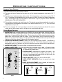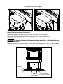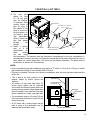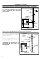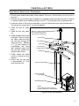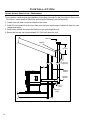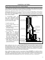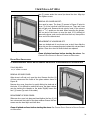
1
SHERWOOD INDUSTRIES IS AN ENVIRONMENTALLY RESPONSIBLE COMPANY. THIS MANUAL IS PRINTED ON RECYCLED PAPER. PLEASE KEEP THESE INSTRUCTIONS FOR FUTURE REFERENCE PELLET STOVE MERIDIAN Freestanding and Fireplace Insert OWNER’S MANUAL Contact your building or fire officials about restrictions and installation inspection requirements in your area. PLEASE READ THIS ENTIRE MANUAL BEFORE INSTALLATION AND USE OF THIS PELLET-BURNING ROOM HEATER. FAILURE TO FOLLOW THESE INSTRUCTIONS COULD RESULT IN PROPERTY DAMAGE, BODILY INJURY OR EVEN DEATH. 50-765 Table of Contents Introduction......................................................................................................................................3 Pellet Quality.........................................................................................................................3 Rating Label Location.............................................................................................................3 Important Safety Data............................................................................................................4 Safety Warnings And Recommendations..................................................................................4 Operating Instructions........................................................................................................................6 Automatic Safety Features......................................................................................................6 Control Board Functions.........................................................................................................6 Operating Your Pellet Stove....................................................................................................7 Turning Your Pellet Stove Off..................................................................................................7 Routine Cleaning and Maintenance......................................................................................................8 Installation......................................................................................................................................11 Deciding Where to Locate your Pellet Appliance......................................................................11 Removing Pellet Stove From Pallet.........................................................................................11 Dimensions - Freestanding....................................................................................................12 Dimensions - Fireplace Insert................................................................................................12 Clearances to Combustibles - Freestanding............................................................................13 Alcove Clearances - Freestanding..........................................................................................13 Clearances to Combustibles - Fireplace Insert.........................................................................14 Installation of Pedestal and Leveling Legs - Fireplace Insert....................................................14 Installing Hopper Cover and Adjusting Hopper Height - Fireplace Insert...................................14 Mobile Home Installation - Freestanding................................................................................15 Exhaust And Fresh Air Intake Locations.................................................................................16 Outside Fresh-Air Connection................................................................................................16 Vent Termination Requirements.............................................................................................17 Corner Through Wall Installation - Freestanding.....................................................................18 Horizontal Exhaust Through Wall Installation - Freestanding.....................................................18 Vertical Rise with Horizontal Termination Installation (Recommended) - Freestanding...............20 Through Concrete Wall With Vertical Rise Installations - Freestanding......................................20 Inside Vertical Installations - Freestanding.............................................................................21 Outside Vertical Installations - Freestanding...........................................................................22 Hearth Mount Installation - Freestanding...............................................................................23 Installation with Exterior Mounted Exhaust Blower - Freestanding............................................24 Through Wall Vertical Installation With Exhaust Blower - Freestanding......................................26 Masonry Fireplace Insert Installation - Fireplace Insert...........................................................27 Installation and Removal of Control Panel in The Surround Panel - Fireplace Insert...................28 Assembly and Installation of Insert Surround Panels - Fireplace Insert.....................................28 Plated Trim Installation.........................................................................................................30 Plated Door Installation........................................................................................................31 Thermostat Installed............................................................................................................32 Slider/Damper Setting..........................................................................................................32 Troubleshooting...............................................................................................................................34 Fuses..................................................................................................................................36 Wiring Diagram................................................................................................................................37 Parts List.........................................................................................................................................38 Parts Diagram - Freestanding Steel....................................................................................................40 Parts Diagram - Insert Steel..............................................................................................................41 Parts Diagram - Components............................................................................................................42 Warranty.........................................................................................................................................43 Installation Data Sheet.....................................................................................................................44 2 Introduction PELLET QUALITY: Pellet quality is important, please read the following: Your enviro pellet stove has been designed to burn wood pellets only. Do not use any other type of fuel, as this will void any warranties stated in this manual. The performance of your pellet stove is greatly affected by the type and quality of wood pellets being burned. As the heat output of various quality wood pellets differs, so will the performance and heat output of the pellet stove. CAUTION: It is important to select and use only pellets that are dry and free of dirt or any impurities such as high salt content. Dirty fuel will adversely affect the operation and performance of the unit and will void the warranty. The Pellet Fuel Industries (P.F.I.) has established standards for wood pellet manufacturers. We recommend the use of pellets that meet or exceed these standards. Ask your dealer for a recommended pellet type. P.F.I. PELLET STANDARDS: Fines (fine particles)......1% maximum through a 1/8” screen Bulk Density..................40 pound per cubic foot minimum Size..............................1⁄4” to 5/16” diameter 1⁄2 – 11⁄2” long maximum Ash Content..................1% maximum (Premium grade) ..................3% maximum (Standard grade) Moisture Content...........8% maximum Heat Content.................approximately 8200 Btu per pound minimum ASH: The ash content of the fuel and operation of your stove will directly determine the frequency of cleaning. The use of high ash fuels may result in the stove needing to be cleaned daily. A low ash fuel may allow longer intervals between cleaning. CLINKERING: [clinkers are silica (sand) or other impurities in the fuel that will form a hard mass during the burning process]. This hard mass will block the air flow through the Burn Pot Liner and affect the performance of the stove. Any fuel, even approved types, may tend to clinker. Check the Burn-Pot Liner daily to ensure that the holes are not blocked with clinkers. If they become blocked, remove the liner (when the unit is cold) and clean/scrape the clinkers out. Clean the holes with a small pointed object if required. Refer to the section Routine Cleaning and Maintenance. PELLET FEED RATES: Due to different fuel densities and sizes, pellet feed rates may vary. This may require an adjustment to the slider damper setting or to the auger feed trim setting on low. Since Sherwood Industries Ltd. has no control over the quality of pellets that you use, we assume no liability for your choice in wood pellets. Store pellets at least 36” (1 m) away from the pellet stove. RATING LABEL LOCATION: Freestanding: The rating label is located on the inside of the hopper lid. Insert: The rating label is located on the hopper cover. 3 Introduction IMPORTANT SAFETY DATA: Please read this entire Owner’s Manual before installing or operating your ENVIRO Pellet Stove. Failure to follow these instructions may result in property damage, bodily injury or even death. Contact your local building or fire official to obtain a permit and any information on installation restrictions and inspection requirements for your area. To prevent the possibility of a fire, ensure that the appliance is properly installed by adhering to the installation instructions. An ENVIRO dealer will be happy to assist you in obtaining information with regards to your local building codes and installation restrictions. Be sure to maintain the structural integrity of the home when passing a vent through walls, ceilings, or roofs. The stove’s exhaust system works with negative combustion chamber pressure and a slightly positive chimney pressure. It is very important to ensure that the exhaust system be sealed and airtight. The ash pan and viewing door must be locked securely for proper and safe operation of the pellet stove. Do not burn with insufficient combustion air. A periodic check is recommended to ensure proper combustion air is admitted to the combustion chamber. Setting the proper combustion air is achieved by adjusting the slider damper located on the left side of the stove. When installing the stove in a mobile home, it must be electrically grounded to the steel chassis of the home and bolted to the floor in accordance with applicable local, state or federal codes. Make sure that the structural integrity of the home is maintained and all construction meets local building codes. Minor soot or creosote may accumulate when the stove is operated under incorrect conditions such as an extremely rich burn (black tipped, lazy orange flames). If you have any questions with regard to your stove or the above-mentioned information, please feel free to contact your local dealer for further clarification and comments. SAFETY WARNINGS AND RECOMMENDATIONS: Caution: Do not connect to any air distribution duct or system. Do not burn garbage or flammable fluids such as gasoline, naptha or engine oil. Unit hot while in operation. Keep children, clothing and furniture away. Contact may cause skin burns. FUEL: This pellet stove is designed and approved to only burn wood pellet fuel with up to 3% ash content. Dirty fuel will adversely affect the operation and performance of the unit and may void the warranty. Check with your dealer for fuel recommendations. THE USE OF CORDWOOD IS PROHIBITED BY LAW. SOOT: Operation of the stove with insufficient combustion air will result in the formation of soot which will collect on the glass, the heat exchanger, the exhaust vent system, and may stain the outside of the house. This is a dangerous situation and is inefficient. Frequently check your stove and adjust the slider/ damper as needed to ensure proper combustion. See: INSTALLATION - SLIDER/DAMPER SETTING. CLEANING: There will be some build up of fly ash and small amounts of creosote in the exhaust. This will vary due to the ash content of the fuel used and the operation of the stove. It is advisable to inspect and clean the exhaust vent semi-annually or every two tons of pellets. 4 Introduction ASHES: Disposed ashes should be placed in a metal container with a tight fitting lid. The closed container of ashes should be on a non-combustible floor on the ground, well away from all combustible materials pending final disposal. If the ashes are disposed of by burial in soil or otherwise locally dispensed, they should be retained in the closed container until all cinders have been thoroughly cooled. ELECTRICAL: The use of a surge protected power bar is recommended. The unit must be grounded. The grounded electrical cord should be connected to a standard 115 volts (4.6 Amps), 60 hertz electrical outlet. Be careful that the electrical cord is not trapped under the appliance and that it is clear of any hot surfaces or sharp edges and also must be accessible. If this power cord should become damaged, a replacement power cord must be purchased from the manufacture or a qualified ENVIRO dealer. This unit’s maximum power requirement is 520 watts. GLASS: Do not abuse the glass by striking or slamming the door. Do not attempt to operate the stove with broken glass. The stove uses ceramic glass. Replacement glass must be purchased from an ENVIRO dealer. Do not attempt to open the door and clean the glass while the unit is in operation or if glass is hot. To clean the glass, use a soft cotton cloth and mild window cleaner, gas or wood stove glass cleaner, or take a damp paper towel and dip into the fly ash. This is a very mild abrasive and will not damage the glass. FLAMMABLE LIQUIDS: Never use gasoline, gasoline-type lantern fuel, kerosene, charcoal lighter fluid, or similar liquids to start or “freshen up” a fire in the heater. Keep all such liquids well away from the heater while it is in use. SMOKE DETECTOR: Smoke detectors should be installed and maintained in the structure when installing and operating a pellet burning appliance. OPERATION: The ash pan and door must be closed securely for proper and safe operation of the pellet stove. Also ensure all gaskets on the door are checked and replaced when necessary. KEEP ASH PAN FREE OF RAW FUEL. DO NOT PLACE UNBURNED OR NEW PELLET FUEL IN ASH PAN. A fire in the ash pan may occur. INSTALLATION: Be sure to maintain the structural integrity of your home when passing a vent through walls, ceilings, or roofs. It is recommended that the unit be secured into its position in order to avoid any displacement. DO NOT INSTALL A FLUE DAMPER IN THE EXHAUST VENTING SYSTEM OF THIS UNIT. DO NOT CONNECT THIS UNIT TO A CHIMNEY FLUE SERVING ANOTHER APPLIANCE. FRESH AIR: Outside Fresh Air connection is optional. Must be connected to all units installed in Mobile and “Air Tight Homes” (R2000) or where required by local codes. Consider all large air moving devices when installing your unit and provide room air accordingly. Limited air for combustion may result in poor performance, smoking and other side effects of poor combustion. If you have any questions with regards to your stove or the above-mentioned information, please feel free to contact your local dealer for further clarification and comments. SINCE SHERWOOD INDUSTRIES LTD. HAS NO CONTROL OVER THE INSTALLATION OF YOUR STOVE, SHERWOOD INDUSTRIES LTD. GRANTS NO WARRANTY IMPLIED OR STATED FOR THE INSTALLATION OR MAINTENANCE OF YOUR STOVE. THEREFORE, SHERWOOD INDUSTRIES LTD. ASSUMES NO RESPONSIBILITY FOR ANY CONSEQUENTIAL DAMAGE(S). SAVE THIS INSTRUCTION MANUAL FOR FUTURE REFERENCE 5 Operating Instructions AUTOMATIC SAFETY FEATURES: Your pellet Stove has the following safety features: A) The stove will shut off when the fire goes out and the exhaust temperature drops below 120 °F (49°C). B) The stove has a high temperature safety switch. If the temperature on the hopper reaches 200 °F (93 °C) the auger will automatically stop, and the stove will shut off when the exhaust temperature cools. If this happens call your local dealer to reset the 200 °F (93 °C) high limit switch. FIND THE REASONS WHY THE UNIT OVERHEATED. C) This unit has a convection fan control over-ride. This function causes the convection fan to reach its full speed when the temperature at the back of the firebox reaches 160 °F (71 °C). This is a normal safety feature of your unit. D) The unit is equipped with a vacuum switch to monitor the venting; if it becomes blocked the vacuum switch will turn off the auger and the #2 light on the control board will flash. CONTROL BOARD FUNCTIONS: 1. AUGER TRIM: Used to change feed rates on LOW ONLY for poorer quality fuels. Push the Auger Trim button until the number 1 and 5 lights appear on the Heat Level Indicator. This will increase the feed rate to four (4) seconds ON time Auger pulse. This is done only on LOW to allow the burning of poor quality fuels. Push the button until the number 1 and 4 lights appear, this will reduce the Auger On time to two (2) second. This setting is for high-grade fuel only. Push the button until just the number 1 light is on, this is for a three (3) second on time (standard setting). 2. CONVECTION BLOWER CONTROL: Used to turn the convection blower ON/OFF. If the Blower is left off, and the sensor located on the air jacket reaches 160 °F (71 °C), the Convection blower will automatically come on HI speed to cool the unit. Leave the convection blower ON for peak efficiency 3. AUGER PULSE LIGHT: This light will flash in conjunction with the auger. 4. MANUAL AUGER FEED: If the unit runs out of fuel, this button can be used to “prime the auger system”. This button will turn off after 60 seconds and then must be released and pressed again. 1 7 2 6. ON/OFF BUTTON: Used to turn the unit ON and OFF. 3 7. HEAT OUTPUT INDICATOR: Shows the present heat output setting. 4 5. SYSTEM LIGHT: Responsible for signaling the state of the control board. When the light is flashing during start-up, the stove is in an automatic start mode. When the light is solid, the Heat Level Setting can be altered. 5 8. HEAT LEVEL ADJUSTMENT: When pressed, will change the heat setting of the unit from low to high. 6 8 Auger Trim Auger Trim 5 4 Figure 1: Circuit Board Control Panel Decal. 6 Auger Trim 1 3 Seconds "ON" Factory Setting 2 Seconds "ON" 1 4 Seconds "ON" 1 Figure 2: Auger trim and heat level indicator. Operating Instructions OPERATING YOUR PELLET STOVE: PRE-BURN INSTRUCTIONS: The burn pot liner holes must be clear and the liner installed correctly against the ignitor tube for proper operation. Check the hopper for enough pellets to start the unit. DO NOT OPERATE THE UNIT WITH THE DOOR OR ASH PAN OPEN. MANUAL MODE: To START: Press the ON / OFF button. The stove will turn on. The system light will flash. The Auger Light will flash with each pulse of the auger (the Auger Feed Rate is pre-programmed during start-up). The Heat Level Indicator will show the Heat Level that the stove will run at after start-up. If this is the first time the unit has been started or the unit has run out of fuel, the auger will need to be primed. Press the Manual Auger Feed button until fuel starts to drop into the Burn Pot Liner (see “OPERATING INSTRUCTIONS - CONTROL BOARD FUNCTIONS”). To OPERATE: When a fire has been established, the System Light will turn solid (after approximately 10 - 15 minutes) and the Auger Light will continue to flash to the corresponding Heat Level setting. The Heat Level button can now be pressed at this time to change the desired Heat Level Output setting. The convection blower (room air blower) will turn on. The speed of this blower is controlled by the setting of the heat level output indicator. The convection blower can be turned OFF by depressing the convection blower control button. When the air jacket reaches 160 °F (71 °C) the convection blower will come ON High, cooling the unit. For the best efficiency and to prevent cycling, the convection blower should be left on at all times. When operating on LOW HEAT LEVEL, the feed rate can be adjusted, using the auger trim, for different quality fuels. These settings can be used if the fire keeps going out on low (for poor quality fuel) or if the low setting is too hot for the room (see “OPERATING INSTRUCTIONS - CONTROL BOARD FUNCTIONS”). THERMOSTAT / SWITCH MODE: INITIAL START-UP: See above OPERATION - HI / LOW mode: When the thermostat contacts are closed the stove settings are adjustable as per Manual Mode (see above). When the thermostat contacts open, the circuit board will take control of the settings. The stove will drop down to a low burn until the thermostat contacts close again. This low burn setting can be adjusted for different fuel qualities (see “OPERATING INSTRUCTIONS - CONTROL BOARD FUNCTIONS”). The stove will come back to the previous HEAT LEVEL setting when the thermostat contacts close again. OPERATION – ON / OFF mode: When the thermostat contacts close, the unit will light automatically. Once up to temperature, the stove operates the same as in manual mode (see above). When the thermostat contacts open, the unit automatically begins its shutdown routine. The stove will re-light when the thermostat contacts close again. TURNING YOUR PELLET STOVE OFF: • MANUAL and HI / LOW mode: To turn the unit OFF, simply press the ON / OFF button. This will stop the feed of pellets. The blowers will continue to operate and cool the stove down. When cool enough, the stove will turn off. • ON / OFF mode: To turn the unit OFF, turn the thermostat down or off. DO NOT unplug unit while Combustion fan is operating. This may lead to smoke escaping from the stove. 7 Routine Cleaning and Maintenance The following list of components should be inspected and maintained routinely to ensure that the appliance is operating at its optimum and giving you excellent heat value: 2-3 Days / Weekly Burn Pot and Liner Ash Pan Inside Firebox Door Glass Heat exchanger tubes Ash pan and Door gaskets Door Latch Semi-annually or 2 Tons of Fuel Exhaust Vent Fresh air Intake Tube Blower Mechanisms Heat exchanger tubes Behind firebox liners All Hinges Post Season Clean-up Burn Pot Liner Ignitor Air Intake Tube TOOLS REQUIRED TO CLEAN UNIT • Torx T-20 Screwdriver • 5/16” Wrench or Socket Burn Pot • Brush • Soft Cloth • Vacuum with fine filter bag BURN POT AND LINER (2-3 days) Figure 3: Burn pot assembly. Cleaning of the burn pot and liner must only be done when stove is cold. To remove the burn pot and burn pot liner, open the door using the door handle provided (located on the right-hand side of the stove). Swing the door open. Lift the liner from the burn pot. Lift the burn pot from the firebox by gently lifting up the front of the burn pot, then sliding the assembly from the air intake tube and the ignitor cartridge. This is the ‘pot’ where the pellets are burned. Every two to three days (when the unit is cold), remove the burn-pot liner from the stove and inspected it to ensure proper air flow through the liner. Failure to keep the liner clean may cause a build up of fuel past the burn pot liner and up the drop tube. This will cause the auger to jam and may result in pellets burning in the drop tube and hopper. Using a metal scrapper, remove material that has accumulated or is clogging the liner’s holes. Then dispose of the scrapped ashes from the liner and from inside the burn-pot. Place the burn-pot back into the stove, making sure that the pipes are properly inserted into the burn pot. Place the liner back into the burn-pot, making sure that the ignitor hole in the liner is aligned with the ignitor tube. Pushing the liner up against the ignitor tube. If, after long periods of burning, the fire continually builds up and overflows the burn pot or there is a build up of clinkers, this is an indication that the pellet fuel quality is poor or the stove may need cleaning. Check the stove for ash build up (clean if required) and adjust the slider / damper to produce the proper clean combustion. DOOR GLASS CLEANING (2-3 days) Cleaning of the glass must only be done when stove is cold. Open the door by lifting the handle. The glass can be cleaned by wiping down the outside and inside of the glass with a dry soft cloth. If the glass has build up that can not be removed with only the cloth, clean the glass using paper towel and a gas appliance glass cleaner, this may be purchased through most dealers. If a gas appliance glass cleaner is not available, use a damp paper towel dipped in fly ash to clean the glass. After the glass has been cleaned use the dry soft cloth to wiping down the outside and inside of the glass DOOR LATCH (2-3 days) Check the door latch every time the door is opened or closed to ensure proper movement. 8 Routine Cleaning and Maintenance ASH PAN AND DOOR GASKETS (weekly) After extended use the gasketing may come loose. To repair this, glue the gasketing on using hightemperature fiberglass gasket glue available from your local ENVIRO dealer. This is important to maintain an airtight assembly. ASH PAN (weekly) The ash pan is located under the burner. Dump the ashes into a metal container stored away from combustibles. Monitor the ash level every week. Remember that different pellet fuels will have different ash contents. Ash content is a good indication of fuel efficiency and quality. Refer to “INTRODUCTION SAFETY WARNINGS AND RECOMMENDATIONS” for disposal of ashes. Freestanding: To remove the ash pan, simply turn the knob and pull out towards the front. Insert: To remove the ash pan open the door, remove the burn pot liner and the burn pot, then pull the ash pan out. DO NOT PLACE UNBURNED OR RAW PELLET FUEL IN ASH PAN. HEAT EXCHANGER TUBES (weekly) Tube cleaner rod Open the door and the rod is located under the unit top, in the center of the stove just behind the door (see Figure 4). This handle is to be pushed in and out a few times (ONLY WHEN THE UNIT IS COLD) in order to clean away any fly ash that may have collected on the heat exchanger tubes. As different types of pellets produce different amounts of ash, cleaning of the tubes should be done on a regular basis to enable the unit to run efficiently. FRESH AIR INTAKE (season) Figure 4: Heat Exchanger Tube Cleaner. Inspect periodically to be sure that it is not clogged with any foreign materials. EXHAUST VENT (season) This vent should be cleaned every year or after two (2) tons of pellets. We recommend contacting your dealer for professional cleaning. To clean the vent pipe, tap lightly on the pipe to dislodge any loose ash. Open the bottom of the “T” to dump the ash, then vacuum as much of the ash out of the vent pipe as possible. BLOWER MECHANISMS (season) Unplug the stove then open the right and left side panels to access the two blowers. Vacuum all dust from motors. DO NOT lubricate the motors. Check gaskets and replace if needed. ALL HINGES (season) Check all the hinges on the unit to ensure proper movement. 9 Routine Cleaning and Maintenance EXHAUST PASSAGES (season) Removal of the firebox backing for biannual cleaning (refer to Figure 5): • Open the door by lifting the handle, remove the burn pot and burn pot liner. • Lubricate all screws with penetrating oil. • Remove the four (4) screws that hold the brick liner retainers in place. Remove side brick liners by sliding them forward then out. • Pull the center panel out. • Vacuum and clean thoroughly. Installation of firebox backing: • Insert center panel with backing. • Place the two (2) side panels back into the firebox and reinstall the two (2) retainers using two (2) screws on each side. • Replace the burn pot and burn pot liner • Close the glass door and secure. Figure 5: Firebox Components Removal. POST SEASON CLEAN-UP Once you are finished using the pellet appliance for the season, unplug the stove for added electrical protection. It is very important that the stove be cleaned and serviced as stated above. CLEANING PLATED SURFACES Painted surfaces should be wiped with a damp cloth periodically. It is important to note that fingerprints and other marks can leave a permanent stain on plated finishes. To avoid this, give the surface a quick wipe with denatured alcohol on a soft cloth BEFORE lighting the fireplace. Never clean surfaces when they are hot. Do not use other cleaners or abrasives as they may leave a residue or scratches, which can become permanently etched into the surface. FIREBOX PANEL The paint on the steel firebox panels may peel. This is due to extreme conditions applied to the paint and is in no way covered by warranty. REPLACING DOOR GLASS It is recommended that your ENVIRO dealer replace the glass if broken. The door glass is made of high temperature PYRO CERAMIC 5 mm thick. The center panel is 15.4” x 9.0” (39.0 cm x 22.9 cm) and side panels are 2.6 x 9.0 inches (6.7 cm x 22.9 cm). They must be replaced with (Part # EF-062). Substitute materials will not be permitted. 10 Installation DECIDING WHERE TO LOCATE YOUR PELLET APPLIANCE: 1. Check clearances to combustibles (see INSTALLATION - CLEARANCES TO COMBUSTIBLES - FREESTANDING, INSTALLATION - ALCOVE CLEARANCES - FREESTANDING, and INSTALLATION - CLEARANCES TO COMBUSTIBLES - FIREPLACE INSERT. 2. Do not obtain combustion air from an attic, garage or any unventilated space. Combustion air may be obtained from a ventilated crawlspace. 3. Do not install the stove in a bedroom. 4. You can vent the stove through an exterior wall behind the unit or connect it to an existing masonry or metal chimney (must be lined if the chimney is over 6” (15 cm) diameter, or over 28 inches² (180 cm²) cross sectional area). An interior vent can be used with approved pipe passing through the ceiling and roof. 5. Locate the stove in a large and open room that is centrally located in the house. This will optimize heat circulation. 6. The power cord is 8 feet (2.43 m) long and may require a grounded extension cord to reach the nearest electrical outlet. REMOVING PELLET STOVE FROM PALLET: To remove your new stove from its pallet, remove the two (2) screws securing the bottom to the pallet. Freestanding: One screw can be easily seen from behind but to access the second screw the ashpan must be removed. Fireplace Insert: There is one screw on either side of the bottom. Figure 6: Removing Freestanding Stove From the Pallet. Figure 7: Removing Insert Stove From the Pallet. 11 Installation DIMENSIONS - FREESTANDING: 32 1/2" (826mm) 24 7/8" (632mm) 24 3/4" (629mm) Figure 8: Meridian Freestanding Dimensions. DIMENSIONS - FIREPLACE INSERT: 23 7/8" (605mm) 12 7/8" (326mm) 23 3/4" (604mm) 22 7/8" (583mm) Figure 9: Meridian Fireplace Insert Dimensions. 12 Installation CLEARANCES TO COMBUSTIBLES - FREESTANDING: These dimensions are minimum clearances but it is recommended that you ensure sufficient room for serving, routine cleaning and maintenance. Back wall 3" (76mm) Adjacent wall Side wall 2" (51mm) 6" (152mm) Minimum 6" (150mm) Figure 10: Meridian on Floor Protection. Figure 11: Minimum Clearances to Combustibles for Freestanding Meridian. This pellet stove requires floor protection. The floor protection must be non-combustible, extending beneath the stove the full width and depth of the unit including 6“ (150 mm) in front for ember protection. ALCOVE CLEARANCES - FREESTANDING: Minimum Width 36" (914mm) Minimum Height 48" (1219mm) Maximum Depth 30" (762mm) Figure 12: Alcove Clearances Freestanding Meridian. 13 Installation CLEARANCES TO COMBUSTIBLES - FIREPLACE INSERT: The fireplace insert must be installed into a masonry fireplace. This model includes a surround faceplate and a pedestal. When installing this unit, ensure that the pedestal is removed from the inside of the hopper and installed on the bottom of the unit. Refer to INSTALLATION - INSTALLATION OF PEDESTAL AND LEVELING LEGS - FIREPLACE INSERT and INSTALLATION - INSTALLING HOPPER COVER AND ADJUSTING HOPPER HEIGHT - FIREPLACE INSERT before proceeding. From the body of the heater to the side wall: 8 inches (203 mm) minimum From the body of the heater to the Facing on masonry fireplace: 8 inches (203 mm) minimum From the body of the heater to the 8” (203 mm) mantle: 8 inches (203 mm) minimum INSTALLATION OF PEDESTAL AND LEVELING LEGS - FIREPLACE INSERT: There are two parts to the Meridian insert pedestal and they can be found inside the hopper. Place unit on its back. Two (2) hex head screws are used on each side of the pedestal (refer to Figure 13). Using a 5/16” wrench or socket attach the pedestal to the bottom of the unit. OPTIONAL: There are two (2) leveling legs and they can be found inside the manual bag. Each leveling leg consists of a long bolt, a hex nut, a washer, and a square bolt with clip (see Figure 14). For installation of the leveling legs the unit should be on its back and a 1⁄2” wrench is required for adjustments. Install the square bolts into the square holes in the back corners of the bottom. The square bolt should be inserted from inside the unit so that the clip will be facing up. Thread hex nut onto the bolt till it is approximately 1” (25 mm) from the bolt head, slide washer onto bolt. Thread the bolt into the square nut so length of the bolt shown is the approximately height needed for leveling. When the unit is up right and the bolts can be adjusted to the exact height required. To lock Figure 14: Square Bolt. the bolts at a height tighten the hex nut and washer against the square bolt Leveling Legs Figure 13: Installing Pedestal. INSTALLING HOPPER COVER AND ADJUSTING HOPPER HEIGHT - FIREPLACE INSERT: The hopper cover initially comes upside-down on top of the hopper. To install the hopper cover flip the cover over and fasten in place with four T-20 screws (see Figure 15). The back height of this unit can be set to one (1) of three (3) heights; 19” (483 mm), 211⁄8” (537 mm), 221⁄4” (565 mm). The hopper should be set to the maximum height that can be used in the installation. To change the height of the hopper back up or down, remove the seven (7) T-20 screws, three (3) on each side and one (1) on the back. The screw placement is shown Figure 16. Move the hopper assembly to the required setting and replace the screws. When the hopper back is in place it is recommended that silicone is used to seal the bottom lip of the hopper back and sides 14 Installation Figure 15: Hopper Cover Screw Placement. Figure 16: Hopper Extension Screw Placement. MOBILE HOME INSTALLATION - FREESTANDING: ● Secure the heater to the floor using the holes in the pedestal of the appliance. ● Ensure the unit is electrically grounded to the chassis of your home (permanently). WARNING: Do not install in a room people sleep in. CAUTION: The structural integrity of the manufactured home floor, wall and ceiling/roof must be maintained • Outside fresh air is mandatory. Secure outside air connections directly to fresh air intake pipe and secure with three (3) screws evenly spaced. Hearth Pad Flooring Steel Frame 1/4" Lag bolts securely fastened Ground wire directly connected to metal chassis. Figure 17: Mobile Home Install Mounting. 15 Installation EXHAUST AND FRESH AIR INTAKE LOCATIONS: 5 3/4" (146mm) 5 3/4" (146mm) 5/8" 18 (473mm) 1/16" 13 (332mm) 9 1/16" (229mm) 3 7/16" (87mm) 10 7/8" (277mm) 11 7/16" (291mm) 1" (25mm) 1" (25mm) 6 1/8" (156mm) Figure 19: Meridian Insert Inlet and Outlet Location. 6 11/16" (170mm) Figure 18: Meridian Freestanding Inlet and Outlet Location. EXHAUST Base of unit to center of flue Side of unit to center of flue Center of unit to center of flue Freestanding 18 5⁄8” (473 mm) 6 11/16” (170 mm) 5 3⁄4” (146 mm) Insert 9 1/16” 6 1⁄8” 5 3⁄4” (229 mm) (156 mm) (146 mm) FRESH AIR INTAKE. Base of unit to center of intake Side of unit to center of intake Center of unit to center of flue 13 1/16” 11 7/16” 1” 3 7/16” 10 7⁄8” 1” (87 mm) (277 mm) (25 mm) (332 mm) (291 mm) (25 mm) INSTALL VENT AT CLEARANCES SPECIFIED BY THE VENTING MANUFACTURER OUTSIDE FRESH-AIR CONNECTION: Outside fresh air is mandatory when installing this unit in airtight homes and mobile homes. A Fresh-air intake is strongly recommended for all installations. Failure to install intake air may result in improper combustion as well as the unit smoking during power failures. When connecting to an outside fresh air source, do not use plastic or combustible pipe. A 2” minimum (51 mm) ID (inside diameter) steel, aluminum or copper pipe should be used. It is recommended, when you are installing a fresh air system, to keep the number of bends in the pipe to a minimum. ������� ���� �� �� ��� ��� �������� ����� Figure 20: Outside Air Connection. 16 Installation VENT TERMINATION REQUIREMENTS: IT IS RECOMMENDED THAT YOUR PELLET STOVE BE INSTALLED BY AN AUTHORIZED DEALER/INSTALLER. Table 1: Use in conjunction with Figure 21 for allowable exterior vent termination locations. Letter Minimum Clearance A 24 in (61 cm) Description Above grass, top of plants, wood, or any other combustible materials. B 48 in (122 cm) C 24 in (61 cm) From beside/below any door or window that may be opened. From above any door or window that may be opened. D 24 in (61 cm) To any adjacent building, fences and protruding parts of the structure. E 24 in (61 cm) Below any eave or roof overhang F 12 in (30 cm) To outside corner. G 12 in (30 cm) To inside corner, combustible wall (vertical and horizontal terminations). H 3 ft (91 cm) within a height of 15 ft (4.5 m) above the meter/regulator assembly To each side of center line extended above natural gas or propane meter/regulator assembly or mechanical vent. I 3 ft (91 cm) J 12 in (30 cm) From any forced air intake of other appliance Clearance to non-mechanical air supply inlet to building, or the combustion air inlet to any appliance. K 24 in (61 cm) Clearance above roof line for vertical terminations. L 7 ft (2.13 m) Clearance above paved sidewalk or paved driveway located on public property. 1. Do not terminate the vent in any G K enclosed or semienclosed areas such as a carport, E garage, attic, G B C Opens D F crawlspace, narrow G Opens walkway, closely B Opens L I fenced area, under A a sundeck or porch, H Termination Cap Restriction Zone G Gas Meter Air Supply Inlet or any location that can build up Figure 21: Use in conjunction with Table 1 for allowable exterior vent termination locations. a concentration of fumes such as stairwells, covered breezeway, etc. (Termination not allowed) 2. Vent surfaces can become hot enough to cause burns if touched by children. Non-combustible shielding or guards may be required. 3. Termination must exhaust above the inlet elevation. It is recommended that at least five feet of vertical pipe be installed outside when the appliance is vented directly through a wall, to create some natural draft to prevent the possibility of smoke or odor during appliance shut down or power failure. This will keep exhaust from causing a nuisance or hazard from exposing people or shrubs to high temperatures. In any case, the safest and preferred venting method is to extend the vent through the roof vertically. 4. Distance from the bottom of the termination and grade is 12” (30 cm) minimum. This is conditional upon the plants and nature of grade surface. The exhaust gases are hot enough to ignite grass, plants and shrubs located in the vicinity of termination. The grade surface must not be lawn. 5. If the unit is incorrectly vented or the air to fuel mixture is out of balance, a slight discoloration of the exterior of the house might occur. Since these factors are beyond the control of Sherwood Industries Ltd, we grant no guarantee against such incidents. NOTE: Venting terminals shall not be recessed into walls or siding. 17 Installation CORNER THROUGH WALL INSTALLATION - FREESTANDING: Fresh Air Intake 3" (7.5 cm) Wall thimble manufactured by pellet vent manufacturer. 3" (7.5 cm) Figure 22: Corner Installation. HORIZONTAL EXHAUST THROUGH WALL INSTALLATION - FREESTANDING: Vent installation: install vent at clearances specified by the vent manufacturer. A chimney connector shall not pass through an attic or roof space, closet or similar concealed spaces, or a floor, or ceiling. Where passage through a wall or partition of combustible construction is desired, the installation shall conform to CAN/CSA-B365 Installation Code for Solid-Fuel-Burning Appliances and Equipment. Only use venting of L or PL type with an inside diameter of 3 or 4 inches (7.6 or 10.1 cm). 1. Choose a location for your stove that meets the requirements stated in this manual and allows installation with the least amount of interference to house framing, plumbing, wiring, etc. 2. Install a non-combustible hearth pad (where necessary). 3. Place the appliance 15” (37.5 cm) away from the wall. If the stove is to be set on a hearth pad, set the unit on it. 4. Locate the center of the exhaust pipe on the stove. Extend that line to the wall. Once you have located the center point on the wall, refer to pellet vent manufacturer installation instructions for correct hole size and clearance to combustibles. 5. Install the wall thimble as per the instructions written on the thimble. Maintain an effective vapour barrier in accordance with local building codes. 6. Install a length of 3” (76 mm) or 4” (101 mm) vent pipe into the wall thimble. The pipe should install easily into the thimble. 7. Install the fresh air intake (see INSTALLATION - OUTSIDE FRESH AIR CONNECTION). 8. Connect the exhaust vent pipe to the exhaust pipe on the stove. Seal the connection with high temperature silicone. 9. Push the stove straight back, leaving a minimum of 2” (5 cm) clearance from the back of the stove to the wall. Seal the vent pipe to the thimble with high temperature silicone. 18 Installation 10. The pipe must extend at least 12” (30 cm) away from the building. If necessary, bring another length of pipe (PL type) to the outside of the home to connect to the first section. Do not forget to place high temperature silicone around the pipe that passes through the thimble. Exhaust Tube 3" (75mm) or 4" (100mm) "PL" or "L" vent Wall Thimble 45° Elbow with screen or Termination Cap 11. Install a vertical Fresh Air Intake High Temperature RTV pipe, or if all Silicone Required requirements for direct venting Figure 23: Straight through wall Installation. are met, install vent termination. The stainless steel cap termination manufactured by the vent manufacturer is recommended. However, when the vent terminates several feet above ground level and there are no trees, plants, etc. within several feet, a 45° elbow can be used as termination. The elbow must be turned down to prevent rain from entering. NOTE: • Some horizontal through wall installations may require a “T” and 3 to 5 feet (91 to 152 cm) of vertical pipe outside the building to help naturally draft in the unit. • This may be required if a proper burn cannot be maintained, after the stove has been tested and the airflow set. • This is due to the back pressure in the exhaust caused by airflow around the structure. • All sections of pipe must have three (3) screws evenly spaced and all horizontal and vertical vent sections located within the house must have a bead of high temperature silicone installed on the male end of the pipe before installation to create a gas tight seal. Wall framing Horizontal frame for thimble Vent pipe Termination cap • The termination must be 12 inches (30 cm) from the outside wall and 12 inches (30 cm) above the ground. • A 45° elbow with a rodent screen may be used in place of the termination cap (or stainless steel termination hood). Wall thimble ENVIRO Meridian Figure 24: Straight through Wall Installation - Side View. 19 Installation VERTICAL RISE WITH HORIZONTAL TERMINATION INSTALLATION (RECOMMENDED) - FREESTANDING: A 45° elbow with a rodent screen may be used in place of the termination cap (or stainless steel termination hood). Termination cap 90°elbow Wall framing Vertical section of vent pipe Wall strap Horizontal frame for thimble Clean out tee Wall thimble ENVIRO Meridian Figure 25: Through Wall with Horizontal Termination. THROUGH CONCRETE WALL WITH VERTICAL RISE INSTALLATIONS - FREESTANDING: A 45° elbow with a rodent screen may be used in place of the termination cap (or stainless steel termination hood). This is the recommended installation to use if there is a concrete or retaining wall in line with exhaust vent on pellet stove. The termination must be 12 inches (30 cm) from the outside wall and 12 inches (30 cm) above the ground. Horizontal frame for thimble Termination cap Wall thimble 90°elbow Wall framing Vertical section of vent pipe Concrete Wall ������ �������� Clean out tee Figure 26: Vertical rise with Horizontal Termination. 20 Installation INSIDE VERTICAL INSTALLATIONS - FREESTANDING: 1. Choose a stove location that is ideal. See the section “INSTALLATION - DECIDING WHERE TO LOCATE YOUR PELLET APPLIANCE.” 2. Place the unit on the hearth pad (if installed on a carpeted surface) and space the unit in a manner so when the pellet vent is installed vertically, it will be 3” (76 mm) away from a combustible wall. 3. Locate the center of the fresh air intake pipe on the unit. Match that center with the same point on the wall and cut a hole about 2” (51 mm) in diameter. 4. Install the fresh air intake pipe. 5. Install the tee with clean out. 6. Install the pellet vent upward from there. When you reach the ceiling, make sure that the vent goes through the ceiling fire stop. Maintain a 3” (76 mm) distance to combustibles and keep attic insulation away from the vent pipe. Maintain an effective vapor barrier. Rain cap - ensure cap is at least 2 feet (610mm) above the roof at the lowest point Storm collar Roof flashing Roof rafter Fire stop with Support Collar Ceiling joist 7. Finally, extend the pellet vent to go through the roof flashing. 8. Ensure that the rain cap is approximately 24” (610 mm) above the roof. Vertical vent pipe Clean out tee with Pipe adapter ENVIRO Meridian NOTE: All vent sections must maintian 3" (76 mm) clearances to combustibles. Figure 27: Inside Vertical Installation. 21 Installation OUTSIDE VERTICAL INSTALLATIONS - FREESTANDING: To accomplish a outside vertical pipe installation, follow steps 1 through 5 in the “INSIDE VERTICAL INSTALLATIONS - FREESTANDING” section and then finish it by performing the following (refer to Figure 28). 1. Install a tee with clean out on the outside of the house. 2. Install PL vent upward from the tee. Make sure that you install support brackets to keep the vent straight and secure. 3. Install ceiling thimble and secure the flashing as you go through the roof. 4. Ensure that the rain cap is approximately 24” (610 mm) above the roof. Rain cap Flashing 24" (61 cm) 3" (7.5 cm) Clearance 3" (7.5cm) Support bracket Tee with cleanout Type "L" vent Fresh air intake Figure 28: Outside Vertical Installation. 22 Installation HEARTH MOUNT INSTALLATION - FREESTANDING: Damper Removed or Fastened Open Mantel Minimum 8" (20 cm) from top of stove Clean-out Fresh-air intake should com from chimney. If holes already exist fresh-air intake can be taken through back of the fireplace or through the ash dump. Min 6" (150 mm) Rain cap Floor Protection Masonry Fireplace Combustible Floor Storm collar Figure 29: Hearth Mount - Side View. Seal plate (cover plate) 1. Lock fireplace damper in the open position. 2. Install a positive flue connector at the fireplace dampers. 3. Connect a clean-out tee or a 90° elbow to the exhaust pipe. 4. Install flexible stainless steel liner or listed pellet vent to the top of the chimney. Existing masonry flue Vent pipe (single wall stainless flex pipe or solid PL vent) Flexible vent connector (use this 5' [1520 mm] section of pipe to vent past fireplace damper or small shelf) Fireplace damper location Clean out tee Existing fireplace Figure 30: Hearth Mount - Over View. 23 Installation INSTALLATION WITH EXTERIOR MOUNTED EXHAUST BLOWER - FREESTANDING: The MERIDIAN can be equipped with an externally mounted exhaust blower (PART #20-070). This optional kit will include all components necessary to install the exhaust blower on any external vertical wall surface. Choose a location for your stove that meets the requirements stated in this manual and allows installation with the least amount of interference to house framing, plumbing, wiring, etc. Included in the exterior mounted exhaust blower kit are: 1 - Exhaust blower housing box. 1 - Blower cover plate. 1 - Hardware bag Left side with cab side removed 1. Open the left side of the unit and the back grill and disconnect the Exhaust Blower wires from the harness. Remove the exhaust blower by undoing the six (6) 1⁄4 hex head sheet metal screws that fasten the blower to the housing. 2. Remove the back grill from the exterior exhaust vent housing and remove the round cover plate installed on the blower housing. 3. Install the round cover plate over the gasketed opening in the stove where the exhaust motor was removed from. Exhaust motor must be replaced with cover 4. Install the exhaust blower motor in the Exterior Vent Housing Box onto the exhaust blower housing. 5. Follow the procedures for INSTALLATION - HORIZONTAL EXHAUST THROUGH WALL INSTALLATION - FREESTANDING. Place the unit in the desired location. Cut the hole in the wall at the desired location. Install a wall thimble. 6. Drill holes in the wall thimble in the corresponding locations for wire and fresh air if needed. Install wire clamps and feed wire through the hole in the thimble into the house. Tighten clamp on wire and attach green ground wire (at the symbol) with the screw and star washer provided. Exhaust motor 7. Attach a short or an adjustable section of 3” of double wall pellet vent through the wall thimble to the stove. Seal all joints with silicone. Maintain clearances to combustibles. 8. Apply silicone to the pipe in the Exhaust Box, slide the pipe into the exhaust vent. Mount the Exhaust Box to the house. Reinstall the back grill on the Exterior Vent Housing Box. Apply normal venting practices when installing the vertical vent pipe. 9. Connect the wires in the stove. Re-install the Left side and Back Grill on the stove. 10. Set the Slider Damper as described in the INSTALLATION SLIDER/DAMPER SETTING“ section. 24 Complete assembly - Exterior blower & housing Figure 31: Exterior Exhaust Blower. Installation NOTE: Ensure that all vent connections are installed by placing three (3) screws evenly spaced and a small bead of high temperature silicone at each chimney connection. Also ensure that all vertical vent sections are properly supported and that all clearances to combustibles are maintained in accordance with the vent manufacturer’s specifications. Vent termination cap (stainless steel termination hood) or 45° elbow with rodent screen Siding 90° elbow Wall framing Wall strap (recommended with use of vent pipe) Vent pipe or 2 foot (610 mm) riser Wall thimble Pipe adapter (if using 2 foot riser) Exterior blower and housing Horizontal frame for thimble Armour cable supplying power to exterior blower ENVIRO Meridian Figure 32: Exhaust Blower Installation; Horizontal Termination. TO SUPPLY POWER TO THE EXHAUST BLOWER: Install an amour coated electrical cable from the exhaust blower housing, through the wall thimble, and attach to the pre-drilled hole in the left hand rear hopper pillar. Hook up to wires from the wiring harness for the exhaust blower. All electrical connections must be in accordance with local code requirements (see WIRING DIAGRAM). 25 Installation THROUGH WALL VERTICAL INSTALLATION WITH EXHAUST BLOWER - FREESTANDING: Refer to INSTALLATION - INSTALLATION WITH EXTERIOR MOUNTED EXHAUST BLOWER - FREESTANDING and INSTALLATION OUTSIDE VERTICAL INSTALLATIONS - FREESTANDING. Ensure that vent pipe is properly secured to wall using wall straps. Maintain clearances to combustibles on vent pipe as well as unit. Rain Cap Roof sheathing Storm collar Roof flashing Roof rafters Ceiling joists Vent Pipe Exterior wall sheathing Outside vent termination Figure 33: Exhaust Blower Installation; Vertical Termination. 26 Installation MASONRY FIREPLACE INSERT INSTALLATION - FIREPLACE INSERT: The Fireplace insert model requires a surround faceplate and a pedestal. When installing this unit, ensure that the pedestal is removed from the inside of the hopper and installed on the bottom of the unit (Refer to INSTALLATION - INSTALLATION OF PEDESTAL AND LEVELING LEGS - FIREPLACE INSERT). Adjust hopper height (see INSTALLATION - INSTALLING HOPPER COVER AND ADJUSTING HOPPER HEIGHT - FIREPLACE INSERT) and assemble surround panel (see Installation - INSTALLATION AND REMOVAL OF CONTROL PANEL IN THE SURROUND PANEL - FIREPLACE INSERT and Installation - ASSEMBLY AND INSTALLATION OF INSERT SURROUND PANELS - FIREPLACE INSERT) before starting installation. A noncombustible hearth pad must cover combustible flooring underneath, as well as 6” (150 mm) in front of the heater and 6” (150 mm) to the side of the heater Rain Cap Fresh-air intake Steel Plate or Flashing Flexible or Rigid 6" Stainless Steel Liner 1. Install the hearth pad. 2. Lock the fireplace damper in the open position. 3. Install a positive flue connector at the fireplace damper. 4. Connect a tee or 90° degree elbow to the exhaust pipe. 5. This fireplace insert must be installed with a continuous chimney liner of 3 or 4” diameter extending from the fireplace insert to the top of the chimney. The liner must conform to type 3 requirements of CAN/ULC S635. 6. (Recommended) Install fresh air intake either through the back of the fireplace or through the positive flue connector. Damper Removed or Fastened Open Flexible stainless steel pipe connection Mantel Minimum 8" (20 cm) from top of stove Surround Panel Clean-out tee If holes already exist fresh-air intake can be taken through the back of the fireplace or through the ash dump. Min 6" (150 mm) Floor Protection Masonry Fireplace Combustible Floor Figure 34: Installation of Fireplace Insert. When installing the insert into a masonry fireplace DO NOT remove any bricks or masonry, with the following exception; masonry or steel, including the damper plate, may be removed from the smoke shelf and adjacent damper frame if necessary to accommodate a chimney liner. Provided that their removal will not weaken the structure of the fireplace and chimney, and will not reduce protection for combustible materials to less than that required by the national building code. When installing the fireplace insert into a zero clearance fireplace, DO NOT cut or modify any factory firebox parts. If the fireplace insert does not fit into a zero clearance fireplace we recommend you use an ENVIRO freestanding model and install as a hearth mounted unit. Install a 3” (76 mm) flex pipe from the stove to the top of the chimney (see “INSTALLATION - HEARTH MOUNT INSTALLATION - FREESTANDING”). 27 Installation INSTALLATION AND REMOVAL OF CONTROL PANEL IN THE SURROUND PANEL - FIREPLACE INSERT: When installing the circuit board control panel into the surround panel, the surround does not need to be assembled. The circuit board will be found in the firebox. Place the circuit board control panel on the backside of the right surround panel so the hinge is on the outside and the top and bottom holes on the control panel line up with those on the surround. Attach using two (2) T-20 screws through the front of the surround into the circuit board control panel. ���� After the surround has been assembled and is ready to be installed on the unit plug the wiring harness into the control panel (see Figure 35). REMOVAL: When maintenance is required on the unit the surround must be removed. Pull the surround straight up till it stops then pull it out about 4” (10 cm) and rest the surround on top of the unit while the control panel is removed or disconnected. If electrical connection is required for the maintenance remove the circuit board control panel from the surround. Figure 35: Right Panel - Back. If electrical connection is not required for the maintenance remove the wiring harness from the bottom of the circuit board control. Figure 36: Right Panel - Front. ASSEMBLY AND INSTALLATION OF INSERT SURROUND PANELS - FIREPLACE INSERT: The trim set for your surround panel must be installed before installing the surround panel onto the unit, if not already done. 1. To assemble the surround panels, lay the panels face down on a soft flat surface and align the outer edges of the sides with the top panel. Using four (4) T-20 screws up through the side panels into the top (see Figure 37). 2. Remove the backing off the magnets and stick them inside the trim pieces as shown in Figure 38. 3. Attach one side trim to the top trim, using a corner bracket (see Figure 39) to secure pieces together. There are two (2) main pieces to each corner bracket (see Figure 40). When installing the corner pieces into the trim, the “B FACE” sides must face each other and the screw heads are to face out. With the bracket in place and the top and a side trim snug together, use a flat head screwdriver to turn the two (2) screws in the bracket to tighten it into the trim. 4. Slide the two (2) attached trim pieces onto the surround panel. 5. Attach the other side trim piece to the top trim, using the same method used in Step 3. 28 Figure 37: Assembled Surround Panel. Installation 6. Place the second side of the trim on the surround panel in the same manner used on the first side and secure in the same manner. 7. On the side trims, there are holes 2” (50 mm) from either end. Use a Phillips screwdriver to place a #8 screw 11⁄4” long in each hole and tighten (refer to Figure 41). This will keep the trim tight against the surround. Magnetic Strips Figure 38: Magnet placement on trim. 8. Place the assembled surround panel around the stove; align the slots with the screw heads. Push surround in then down to engage the surround slots on the mounting screws (see Figure 42). Make sure the top surround panel sits flat behind the stove top. Surround Panel Figure 39: Corner brackets for trim. Figure 40: Two pieces of corner bracket. #8 screw Side Trim Surround Panel Figure 41: Screw to hold the trim against the surround. Figure 42: Installed Surround Panel. 29 Installation PLATED TRIM INSTALLATION: TO AVOID PERSONAL INJURY DO NOT REMOVE OR REPLACE TRIMS WHEN PELLET STOVE IS HOT! KIT COMPONENTS: Quantity Upper Cabinet Trim Description 2 Upper Cabinet Trim 2 Lower Cabinet Trim 1 Top Trim 3 Louver 4 #8 nut plated (spares) Lower Cabinet Trim TOOLS REQUIRED: ● T-20 screwdriver Left Cabinet Side #8 Hex Nut (x8) #8 Stud (x8) ●11/32” socket Figure 43: Right cab side with upper and lower cabinet trims. REMOVAL OF SIDE TRIMS: When stove is off and cool, open the door. Remove the two (2) screws on the right cab side (at top and bottom of front flange) and the two (2) screws on the left cab side (one above and one below hinge). The cab sides have hinges at the back so they can swing open when the screws have been removed. Remove the trims that will be replaced by unfastening the #8 hex nuts (four (4) for each piece of trim) by hand. Carefully remove the trim from the studs. REPLACEMENT OF SIDE TRIMS: Top Front Place the new trim pieces on their corresponding studs and finger tighten the #8 hex nuts (four (4) for each piece of trim). Refer to Figure 43. Close both cab sides and replace the two (2) screws on each side. #8 Stud (x6) Top Trim REMOVAL OF TOP TRIM: With door open, undo the two (2) screws on the #8 Hex Nut (x6) underside of the top there are visible under the angled Hand Tighten Only corners. Open the hopper lid, remove the two (2) screws Figure 44: Top front with top trim that are found attached to the top under the hopper lid. Pull top forward, lift the top front piece off the stove and turn it over. Remove the six (6) #8 hex nuts and pull the trim off the studs. REPLACEMENT OF THE TOP TRIM: Place the new trim on its corresponding studs (see Figure 44) and finger tighten the six (6) #8 hex nuts. Replace top front on top of the stove, remembering to hook the two (2) front tabs under the corresponding tabs on the stove. Replace the two (2) screws on the top under the hopper lid then close lid. Replace the 30 Installation two (2) screws under the corner lips above the door. Align top then tighten screws. REMOVAL OF LOUVER BAR SET: Door must be open. The three (3) arrows in Figure 45 point to three (3) of the nuts that hold the louvers on. There are three nuts on each end. Remove the six nuts by hand; if the nuts are tight, a 11/32” socket can be used. When removing the louvers, pull one end of the louver up over the stud. If it is difficult to remove the louver, push on one side from the front, then pull the other end off the second stud. REPLACEMENT OF LOUVER BAR SET: Place one slotted end of new louver over a stud, then slide the other slot over the corresponding stud; replace the nuts and hand tighten. Close door when all three louvers are replaced. Figure 45: Door with louvers. Clean all plated surfaces before starting the stove. See CLEANING PLATED SURFACES in ROUTINE CLEANING AND MAINTENANCE. PLATED DOOR INSTALLATION: TO AVOID PERSONAL INJURY DO NOT REMOVE OR REPLACE COVER WHEN PELLET STOVE IS HOT! TOOLS REQUIRED: ●11/32” socket or wrench REMOVAL OF DOOR COVER: When stove is off and cool, open the door. Remove the four (4) #8 hex nuts around the inside of the glass retainer shown in Figure 46. Remove door cover from door by gently sliding the studs out of the holes. If it is difficult to remove the cover, the glass retainer may be pinching the threads on the studs. Slightly loosen the four (4) screws (by each of the studs). REPLACEMENT OF DOOR COVER: Slide new door cover into place and hand tighten the four (4) #8 hex nuts around the inside of the glass retainer. Ensure the four screws are also hand tight and close door. Figure 46: Inner side of Meridian door. Clean all plated surfaces before starting the stove. See CLEANING PLATED SURFACES in ROUTINE CLEANING AND MAINTENANCE. 31 Installation THERMOSTAT INSTALLED: This control board can be placed into two (2) different modes: HI / LOW OPERATION: When the jumper J9 is not jumped then the control board is in a HI / LOW mode operation. If the unit has been placed in the HI / LOW mode, the unit will be taken to a low or idle setting when the thermostat is not calling for heat. When the thermostat calls for heat, the unit will go to the setting that is displayed on the control board Heat Indicator. If the heating load is not great enough when the stove is on low, the high limit switch will turn the stove off and the switch will have to be manually reset. To reset the high limit switch, remove the right cabinet side. The switch is found behind the control panel. Avoid setting off the high limit switch. A) HI / LOW: When the jumper is placed on only one of the J9 pins, then the control board is in a HI / LOW mode of thermostat operation (factory setting). B) ON / OFF: If both pins of J9 are jumped (covered), the control board is in an ON / OFF mode of thermostat operation. Remove jumper wire and install thermostat wires here Figure 47: Pin Placement on Circuit Board. ON / OFF OPERATION: If the control board is placed with J9 jumped then the control board is in a ON / OFF mode of operation. In the ON /OFF thermostat mode, when the thermostat calls for heat, the unit will go through an ignition sequence and light the stove. Once lit the unit will operate at the selected setting displayed on the control board Heat Output Indicator. Once the thermostat stops calling for heat, the unit will stop feeding pellets and begin its shut down sequence until cold then turn off. 1. Install the Low Voltage Thermostat (maximum 24V) in a location that is not to close too the unit but will effectively monitor the desired area to be heated. 2. Open the right cab side to expose thermostat wires and disconnect. Install 18 gauge (see WIRING DIAGRAM) or heavier wire through the grommet in the back, from the stove to the thermostat. Connect thermostat wires to red wires provided. 3. To set the thermostat jumper to the desired mode, remove the two (2) screws holding the circuit board control panel in place. Lower the board and pull out to change jumper. SLIDER/DAMPER SETTING: THE SLIDER / DAMPER MUST BE SET AT TIME OF INSTALLATION, IT IS USED TO REGULATE THE AIRFLOW THROUGH THE PELLET STOVE. A Qualified Service Technician or Installer must set the Slider Damper. The slider damper should be set only on a hot stove (operating for thirty (30) minutes or more) by placing a Magnahelic Pressure Gauge in the firebox (test port is located in the center of the stove just below the door opening). Set the slider damper so that the pressure reads 0.11” w.c. (.028 KPa) on HIGH 32 Installation HEAT LEVEL and when turned down to LOW HEAT LEVEL, a 0.07” to 0.11” w.c. (0.018 to 0.028 KPa). Some fuels may require higher or lower settings. The pressure readings are taken through a hole in the front of the firebox under the door, using a Magnehelic Gauge. Exhaust Blower Exhaust Channel Slider Damper Figure 48: Hole for Pressure test with Magnehelic Gauge. Note: Some parts have been removed in order to see components more clearly. Figure 49: Slider / Damper The slider damper is located behind the left cab side. The door must be open for the cab side to be removed on all models. On freestanding model loosen the two T-20 torx screws, one above and one below hinge, swing open left panel to access. On insert model remove the two (2) T-20 torx screws on the front, one above and one below hinge, and the one T-20 at the top of the cab side under the top front. The combustion exhaust blower is a variable speed blower controlled by the heat output button. This blower will decrease the vacuum pressure inside the stove and as the heat output button is turned down. The vacuum pressure inside the firebox will increase as the combustion exhaust blower increases in speed (higher heat output setting). • If the fire should happen to go out and the heat output indicator has been set on the lowest setting, the Slider Damper should be pushed in slightly, decreasing the air in the firebox. • If, after long periods of burning, the fire builds up and overflows the burn pot or there is a build up of clinkers, this would be a sign that the pellet quality is poor, this requires more primary air, the slider damper must be pulled out to compensate. Pulling the slider damper out gives the fire more air. The easiest way to make sure that an efficient flame is achieved is to understand the characteristics of the fire. • A tall, lazy flame with dark orange tips requires more air – Open slider (pull out) slightly. • A short, brisk flame, like a blowtorch, has too much air – Close slider (push in) slightly. • If the flame is in the middle of these two characteristics with a bright yellow/orange, active flame with no black tips then the air is set for proper operation. SPECIAL NOTES: Pellet quality is a major factor in how the pellet stove will operate. If the pellets have a high moisture content or ash content the fire will be less efficient and has a higher possibility of the fire building up and creating clinkers (hard ash build-up). If this happens, pull the Slider Damper out slightly to increase the air flow to the fire. 33 Troubleshooting DO NOT: ● Service the stove with wet hands. The stove is an electrical appliance, which may pose a shock hazard if handled improperly. Only qualified technicians should deal with possible internal electrical failures. ● Do not remove from the firebox any screws without penetrating oil lubrication. ● Hold the ON / OFF BUTTON down. This is a momentary contact switch and can be damaged if held down too long. WHAT TO DO IF: 1. The stove will not start. 2. The stove will not operate when hot. 3. The exhaust blower will not function normally. 4. Light # 2 on Heat output bar flashing. 5. The auger motor will not function normally. 6. The 200 °F (93 °C) high limit temperature sensor has tripped. 7. The convection blower will not function normally. 8. Ignitor- the pellets will not light. 9. Control settings (Heat Level) has no effect on the fire. 10. The stove keeps going out. *NOTE: All troubleshooting procedures should be carried out by qualified technicians or installers. 1. The stove will not start. üMake sure the stove is plugged in and the wall outlet is supplying power. üPush the ON /OFF button. You may need to wait approximately 30 seconds for circuit board to initiate the stove is on. üIf the control board has been placed in the on/off thermostat mode, then turn the thermostat up to call for heat. üCheck the heat level indicator. - If the # 2 light is flashing refer to “4. Light # 2 on Heat output bar flashing.”) üCheck the fuses on the circuit board (see “TROUBLESHOOTING - FUSES”). üIf the unit still does not start, contact your local service dealer for service. 2. The stove will not operate when hot. üCheck the heat level indicator if a fire is not detected, or if the fire has gone out the #3 light will flash because the exhaust temperature sensor’s contacts have opened. üCheck the hopper for fuel. üIncorrect air damper setting. - Excessive air may consume the fire too quickly before the next drop of fuel, leaving completely unburned fuel in the burn pot liner. - Insufficient air will cause build up, further restricting the air flow through the burn pot liner. This in turn will cause the fuel to burn cold and very slowly. Fuel may build up and smother the fire. In this case clean the burn pot. (Note: the unit may require a change to the vent system or installation of fresh air to correct air to fuel ratio problems). üCombustion blower failure. - The combustion blower is not turning fast enough to generate the proper vacuum in the fire box. Visual check – is the blower motor turning. üCheck the exhaust blower voltage across the blower wires (>=114V on #5 setting and >= 82V on #1 setting). – Replace the Circuit Board if the Voltage reading is less than 82V. with a line voltage >115V AC. üCheck vacuum levels in the exhaust channel by bypassing the vacuum switch, then remove the vacuum 34 Troubleshooting hose from vacuum switch. Check exhaust vacuum readings by placing the open end of the vacuum hose on a Magnahelic Gauge (readings must be above 0.18” to 0.20” W.C. (44.8 to 49.8 Pa) on low fire). If the motor fails to reach a 0.10” W.C. readings, then replace the combustion blower. üPoor quality fuel – insufficient energy in the fuel to produce enough heat to keep the stove burning or operational. üExhaust temperature sensor failure. – Bypass sensor located on exhaust blower if stove now operates properly, the unit may require cleaning or a new sensor. Contact your local dealer for service. üThe burn pot liner may require cleaning. Build up in the burn pot will cause the unit to shut off. üCheck the fuses on the circuit board (see “TROUBLESHOOTING - FUSES”). üContact your local dealer for service. 3. The exhaust motor will not function normally. üOpen the left side access panel; check all connections against the wiring diagram. üSee “2. The stove will not operate when hot.” Section. 4. Light # 2 on Heat output bar flashing (The Vacuum Switch contacts have opened for more than 15 sec.) üPinch, break or blockage in vacuum hose - check hose for pinch points or damage, replace or re-route as required. Blow out vacuum hose üBlocked hose barb on exhaust channel - use a paper clip to clean out hose barb or remove the vacuum hose from the vacuum switch and blow into the hose to remove blockage. üBlocked exhaust / venting system - have stove and venting cleaned and inspected. üSevere negative pressure in area where unit is installed - check the operation by opening a window, does this solve the problem? If it does, install fresh air intake to unit or room. Venting system may require vertical section to move termination into a low pressure zone. üVacuum switch failure - bypass the vacuum switch, if this corrects the problem check for above problems before replacing the vacuum switch. üDamage to gray wires between circuit board and vacuum switch - inspect wires and connectors üCombustion blower failure - the combustion blower is not turning fast enough to generate the proper vacuum in the exhaust channel. Visual check; is the blower motor turning? Check the exhaust blower voltage across the blower wires (>=114V on #5 setting and >= 82V on #1 setting). – Replace the circuit board if the Voltage reading is less than 82V. with a line voltage >114V AC. üCheck vacuum levels in the exhaust channel by bypassing the vacuum switch, then remove the Vacuum hose from Vacuum Switch. Check exhaust vacuum readings by placing the open end of the Vacuum Hose on a Magnahelic Gauge. (readings must be above .10” W.C. on low fire). If the motor fails to reach a 0.10” W.C. readings, then replace the combustion blower To reset Circuit Board after a trouble code - push the ON/OFF button 5. The auger motor will not function normally. üThe burn pot liner may require cleaning. Build up in the burn pot will cause the unit to shut off. üCheck for obstructions in the hopper system. üEnsure door is closed and ash pan is closed. The auger motor will stop if there is not enough vacuum in the stove. üCall your local dealer for service. Auger light flashes but auger motor does not turn at all. üIf the auger gear box does not turn but the motor’s armature does try to spin then the auger is jammed. – Try to break apart jam by poking at the jam through the drop tube. If this fails then empty the hopper and remove the auger cover **remember to re-seal the cover after installation** üCheck the fuses on the circuit board (see “TROUBLESHOOTING - FUSES”). 35 Troubleshooting 6. The 200 °F ( 93 °C) high limit temperature sensor has tripped. üReset sensor and determine cause – was it convection blower failure or 160 °F ( 71 °C) temperature sensor failure? Bypass the 160 °F ( 71 °C) sensor, does the convection blower come on high? If no, replace the blower. If yes, replace sensor (located on the left side of the firewall). üCheck the fuses on the circuit board (see “TROUBLESHOOTING - FUSES”). 7. The convection blower will not function normally. üClean all grill openings at the back and below unit . üPress the fan button; does the fan come on? Press again to verify that the blower turns on; if, not contact your local dealer for service. 8. Ignitor- the pellets will not light. (Everything else in the stove operates but the ignitor will not light the pellets.) üMake sure the burn pot liner is up tight and square to the ignitor tube by pushing the burn pot back against the ignitor tube. üCheck to see if the exhaust blower is operating. If not, contact your local dealer for service. üCheck the fuses on the circuit board (see “TROUBLESHOOTING - FUSES”). NOTE: The ignitor should be bright orange in color. If not replace the ignitor. 9. Control settings (Heat Level) has no effect on the fire. üNote: If the system light is flashing the control board has complete control of the unit. When the units system light becomes solid then control of the unit is given back to the operator. üIf there is no control of the heat level button make sure the thermostat is calling for heat. üCall your local dealer for service. 10. The stove keeps going out. a) If the stove goes out and leaves fresh unburned pellets or cigarette-like ashes in the burn pot liner, the fire is going out before the stove shuts off. üCheck to see that the slider / damper is in the correct position. üTurn the heat level up slightly (poor quality pellets will require slightly higher settings). üSet the auger trim till the #1 and #5 lights are illuminated. b) If the stove goes out and there are partially burned pellets left in the burn pot liner, the stove has shut down due to a lack of air, exhaust temperature, or power failure. üAdjust the slider / damper. üCheck to see if the stove needs a more complete cleaning. üTurn the heat level up slightly (poor quality pellets will require slightly higher settings). üDid the power go out? üContact your local dealer for service. FUSES: F1 is the fuse to the inside of the circuit board controls. If F1 has blown there may have been an input power overload or a short in the convection fan. F2 fuse closest fuse to the outside edge of the circuit board controls. If fuse F2 has blown then there was a electrical overload problem with one of the following parts: ignitor, auger motor, high limit switch, or exhaust blower. 36 Wiring Diagram White Black Armor Cable Supplied Grey Vacuum Switch Grey Black White Blue White Combustion Blower Optional Exterior Exhaust Blower Brown o Power Cord o 120 F (49 C) Exhaust Temperature Sensor Ground Brown Black Red Black White 115V White 220V Blue Common Ignitor J2 115V Black 220V Brown Hot 5 Amp Fueses 5V DC Brown 160oF (49oC) Convection Temperature Sensor Convection Blower Black White Orange Orange Purple Blue Yellow Purple White Auger Motor 200oF (93oC) High Limit Temperature Sensor Thermostat Yellow White Orange Orange Red Grey Grey Brown Brown Connect Thermostat Here Red Red 37 Parts List Reference Number 1 Part Number 120 °F (49 °C) Ceramic Fan Temperature Sensor EC-001 Domestic Power Cord - 115V EC-042 2 Auger Motor - 115V EF-001 3 Convection Blower 115V EF-002 4 Fan Temp Sensor 160 °F (71 °C) EF-013 5 High Limit Temp Sensor 200 °F (93 °C) Manual Reset EF-016 6 Vacuum Switch - 115V EF-017 Silicone Hose EF-018 Aluminum Hose Barb EF-019 7 Auger EF-025 8 Door Handle Complete EF-028 9 Slider Damper Rod with Knob EF-050 10 Glass Set with Tape EF-062 11 Slider Damper Plate EF-064 12 Brass Auger Bushing EF-065 13 Ash Pan Latch (Freestanding) EF-178 Pedestal & Ash Pan Gasket - 10’ (305 cm) EF-208 External Exhaust Back EF5-143 External Exhaust Box EF5-144 External Exhaust Bottom EF5-145 45° Exhaust Adaptor EF5-146 Exhaust Starter Tube 3” x 21⁄2” Long EF5-147 Log Set 20-036 Control Panel Door 20-040 External Exhaust Kit (3” pipe) 20-070 14 38 Description 60° Exterior Exhaust Adaptor 50-096 15 Circuit Board 5 Amp Fuses - 115V (Pair) 50-833 15 Circuit Board - 115V 50-178 Circuit Board Decal 50-179 16 Control Panel Touch Latch 50-323 17 Circuit Board Control Panel 50-330 Circuit Board Stand Offs 50-331 18 Combustion/ Exhaust Blower - 115V 50-473 19 Stainless Steel Burn Pot Liner - Standard 50-474 19 Stainless Steel Burn Pot Liner - High Ash 50-587 20 Flush Handle for Hopper Lid (Freestanding) 50-523 Body Trim Kit - Pewter (Freestanding) 50-620 Body Trim Kit - Gold (Freestanding) 50-621 Body Trim Kit - Antique Copper (Freestanding) 50-622 21 Door Cover - Painted 50-683 21 Door Cover - Pewter 50-623 21 Door Cover - Gold 50-624 21 Door Cover - Antique Copper 50-625 22 Door 50-653 23 Louver Bar Set - Painted 50-654 Parts List Reference Number Description Part Number 23 Louver Bar Set - Gold 50-655 23 Louver Bar Set - Pewter 50-656 23 Louver Bar Set - Antique Copper 50-657 24 Burn Pot 50-658 25 Ash Pan (Freestanding) 50-659 26 Pedestal (Freestanding) 50-660 27 Cabinet Side Left (Freestanding) 50-661 28 Lower Cabinet Trim (1 piece) - Painted (Freestanding) 50-662 28 Lower Cabinet Trim (1 piece) - Gold (Freestanding) 50-663 28 Lower Cabinet Trim (1 piece) - Pewter (Freestanding) 50-664 28 Lower Cabinet Trim (1 piece) - Antique Copper (Freestanding) 50-665 29 Upper Cabinet Trim (1 piece) - Painted (Freestanding) 50-666 29 Upper Cabinet Trim (1 piece) - Gold (Freestanding) 50-667 29 Upper Cabinet Trim (1 piece) - Pewter (Freestanding) 50-668 29 Upper Cabinet Trim (1 piece) - Antique Copper (Freestanding) 50-669 30 Cabinet Side Right (Freestanding) 50-670 31 Top Trim - Painted 50-671 31 Top Trim - Gold 50-672 31 Top Trim - Pewter 50-673 31 Top Trim - Antique Copper 50-674 32 Back Grill (Freestanding) 50-675 33 Hopper Lid (Freestanding) 50-676 34 Top Front (Freestanding) 50-677 35 Tube Cleaner Rod 50-680 36 Brick Panel Set 50-681 37 Brick Retainer Set 50-682 Owner’s Manual - 115V 50-765 38 Regular Panel Set (Insert) 50-769 39 Oversized Panel Set (Insert) 50-770 Trim Kit - Pewter (Insert) 50-771 Trim Kit - Antique Copper (Insert) 50-772 Trim Kit - Gold (Insert) 50-773 40 Regular Panel - Left (Insert) 50-817 41 Regular Panel - Right (Insert) 50-818 42 Regular Panel - Top (Insert) 50-819 43 Oversized Panel - Left (Insert) 50-820 44 Oversized Panel - Right (Insert) 50-821 45 Oversized Panel - Top (Insert) 50-822 46 Cabinet Side - Left (Insert) 50-823 47 Cabinet Side - Right (Insert) 50-824 48 Top Front (Insert) 50-825 49 Ash Pan (Insert) 50-826 50 Hopper Lid (Insert) 50-827 51 Hopper Cover (Insert) 50-828 52 300 Watt Ignitor 115V 50-1067 39 Parts Diagram - Freestanding Steel �� �� �� �� �� �� �� �� �� �� �� �� �� �� �� �� �� �� �� �� �� �� � MERIDIAN - Freestanding Steel Parts �� December 2004 �� �� 40 �� �� �� �� �� �� �� �� �� �� December 2004 �� �� �� MERIDIAN - Insert Steel Parts �� �� Parts Diagram - Insert Steel 41 Parts Diagram - Components MERIDIAN - Components December 2004 � � �� � �� � � � �� �� � 42 � Warranty Sherwood Industries Ltd. gives a five year limited warranty on all steel manufactured parts. A one-year warranty is provided on all electrical components. The above limited warranties are extended only to the original purchaser. There is no warranty on the following parts: ● Glass window ● Fiberglass rope gaskets ● refractory material ● burn pot liner ● paint ● enamel finish or gold plating where it applies **NOTE: The paint on the brick firebox lining may peel. This is due to the extreme conditions applied to the paint and is in no way covered under warranty. WHEN FILING A WARRANTY CLAIM PLEASE COMPLETE THE FOLLOWING INFORMATION ON AN OFFICIAL WARRANTY CLAIM FORM: TO THE DEALER: - Name and address of dealer, - Date of purchase - Name, address and telephone number of purchaser - Name, address and telephone number of installer - Date of installation, and - Serial number of the appliance Ensure that you specify the nature of the complaint, defect, periodical malfunction, etc. TO THE DISTRIBUTOR: - Sign and verify that work and information are correct. - Description and part # of any parts replaced. The limited warranty covers defects in materials and workmanship as long as the products has been installed according to the manual’s instruction. If the product is damaged or broken as a result of mishandling or misuse, the warranty does not apply. Removal and re-installation costs are not covered under this warranty. It is the manufacturer’s option whether to repair or replace the appliance. The shipping cost to and from the factory is to be paid by the consumer. All warranties by the manufacturer are set forth herein and no claim shall be made against the manufacturer on any oral warranty or representation. The manufacturer assumes no responsibility for damage caused by household power fluctuations or power surges. Under Warranty For the do-it-yourself Individual The consumer should be aware that the pellet appliance needs setting using tools that he/she might not have. It is recommended that you have a qualified installer install your pellet appliance Sherwood Industries Ltd. reserves the right to make changes without any notice. 43 Installation Data Sheet The following information must be recorded by the installer for warranty purposes and future reference. NAME OF OWNER: NAME OF DEALER: _________________________________________ _________________________________________ ADDRESS: ADDRESS: _________________________________________ _________________________________________ _________________________________________ _________________________________________ _________________________________________ _________________________________________ PHONE:___________________________________ PHONE:___________________________________ MODEL:___________________________________ NAME OF INSTALLER: SERIAL NUMBER:___________________________ DATE OF PURCHASE: _____________ _________________________________________ (dd/mm/yyyy) DATE OF INSTALLATION:___________(dd/mm/yyyy) ADDRESS: MAGNEHELIC AT INSTALL:___________________ _________________________________________ INSTALLER’S SIGNATURE: _________________________________________ _________________________________________ _________________________________________ PHONE:___________________________________ MANUFACTURED BY: SHERWOOD INDUSTRIES LTD. 6782 OLDFIELD RD. SAANICHTON, BC, CANADA V8M 2A3 www.envirofire.biz December 6, 2004 C-10768 44