1
.....................................
HAWK 2XL Family:
.....................................
ST32151N/W/WC
.....................................
ST31051N/W/WC
.....................................
ST32155N/W/WC
.....................................
ST31055N/W/WC
.....................................
Installation Guide
.....................................
Contents
Preface ........................................................................... 1
Electromagnetic interference ..................................... 1
Things you may need to install the drive ................... 3
Before you begin ............................................................ 6
Drive configuration ......................................................... 10
Set drive ID ................................................................ 11
Select operating features ........................................... 14
I/O line terminators ..................................................... 15
Mounting the drive .......................................................... 22
Configuring the computer for your drive ........................ 32
DOS Installation ......................................................... 32
Formatting .................................................................. 35
Macintosh installation ................................................ 37
Unix installation .......................................................... 37
Troubleshooting .............................................................. 38
Product Repair ................................................................ 40
Technical support services ............................................ 42
Hawk 2XL family product information ............................ 45
© 1996 Seagate Technology, Inc. All rights reserved
Publication Number: 77767490, Revision C
February 1996
Seagate®, Seagate Technology® and the Seagate logo are
registered trademarks of Seagate Technology, Inc. HawkTM,
SeaFAXTM, SeaFONETM, SeaTDDTM, and SeaBOARDTM, are
trademarks of Seagate Technology, Inc. Other product names
are registered trademarks or trademarks of their own.
Seagate reserves the right to change, without notice, product
offerings or specifications. No part of this publication may be
reproduced in any form without written permission of Seagate
Technology, Inc.
Hawk 2XL Family Installation Guide, Rev. C
1
___________________________________________________________________________________________________________________
Preface
This manual is organized to assist you in the installation and
operation of your Seagate Hawk 2XL Family disc drive. Family
models are listed in Hawk 2XL Family Product Information
section. It also provides information to aid in obtaining service
for the drive.
Before attempting any installation, please read through all
applicable sections of this document, including all warnings and
cautions.
Caution.
This equipment generates, uses, and can radiate
radio frequency energy and if not installed and used
in accordance with these instructions, may cause
interference to radio communications.
"HDA" means head-disc assembly. "PCB" means printed circuit
board.
Electromagnetic interference (EMI) considerations
The drive models described herein, as delivered, are designed
for system integration and installation into a suitable enclosure
prior to use. As such, the drive models described herein are
supplied as subassemblies and are not subject to Subpart J of
Part 15 of the FCC Rules and Regulations nor the Radio
Interference Regulations of the Canadian Department of Communications. However, the units have been tested using proper
shielding and grounding and found to be compliant with the
Class A limits of the FCC Rules and the Regulations of the
Canadian Department of Communications.
2
Hawk 2XL Family Installation Guide, Rev. C
_______________________________________________________________________________________________________________________
The physical design characteristics of the drive models described herein, serve to minimize EMI radiation when installed
in an enclosure that provides reasonable shielding. As such, the
drive(s) are capable of meeting the Class B limits of the FCC
Rules and the Regulations of the Canadian Department of
Communications.
Note. It is the end users' responsibility to assure that the drive
models described herein meet the appropriate EMI requirements of their system. Shielded I/O cables may be
required if the enclosure does not provide adequate
shielding. If I/O cables are external to the enclosure,
shielded cables should be used, with the shields grounded
to the enclosure or to the host controller, but not both.
The equipment is designed to provide reasonable protection
against such interference in a residential installation. However,
there is no guarantee that interference will not occur in a
particular installation. If this equipment does cause interference
to radio or television, which can be determined by turning the
equipment on and off, you are encouraged to try one or more of
the following corrective measures:
• Reorient the receiving antenna.
• Move the device to one side or the other of the radio or TV.
• Plug the computer into a different AC power outlet so that the
receiver and computer are on different branch outlets. That is,
circuits controlled by different circuit breakers.
If necessary you should consult your dealer or an experienced
radio/television technician for additional suggestions.
Hawk 2XL Family Installation Guide, Rev. C
3
_______________________________________________________________________________________________________________________
You may find helpful the following booklet prepared by the FCC:
How to Identify and Resolve Radio-Television Interference
Problems. This booklet is available from the Superintendent of
Documents, US Government Printing Office, Washington, DC
20402. Refer to publication number 004-000-00345-4.
Things you may need to install the drive
• Adequate power from your computer power supply
This drive requires 7.5 watts during typical operation, and 6.0
watts when at idle (not reading, writing or seeking). If this drive
is an "add-on" make sure the computer power supply can
supply enough extra power for this drive's needs.
• An antistatic wrist strap
You will need this to reduce the possibility of damaging your
drive by static discharge.
• A #2 Phillips screwdriver
You will need this screwdriver to open your computer and to
insert the drive mounting screws.
• A Torx Size TX-08 driver tool
If your drive has a front panel and you need to install the drive
in a conversion frame kit, this tool will be needed.
• A bootable DOS system diskette for the PC
You will need this diskette, which should contain the DOS
system files and the programs FDISK.EXE and FORMAT.EXE
to partition and format your new hard drive.
4
Hawk 2XL Family Installation Guide, Rev. C
_______________________________________________________________________________________________________________________
• A SCSI* host adapter card for the PC
You may need this if your computer does not already have a
hard drive, if your present drive does not connect to a SCSI
host adapter, or if your present SCSI adapter card cannot
address a drive having the capacity the Hawk 2XL has.
The host adapter card should have instructions with it for
installing the card and assist in the installation of hard disc
drives that it supports.
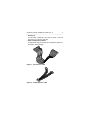
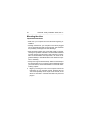
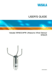
• A 50-pin SCSI interface cable
You will need an interface cable if your computer does not
presently contain a SCSI hard drive. If you are adding a second hard drive you must use an interface cable that has two
drive connectors, one on the end and one in the middle. See
Figure 1.
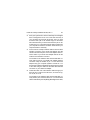
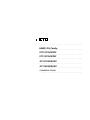
• A Y-shaped drive power cable
You may need this if your computer does not have enough
power cables to supply power to your new hard drive. See
Figure 2.
• Mounting screws
You will need four 6-32 x 1/4 inch (6.4 mm) nonmetric screws
if you mount your drive directly into the drive bay. See Safety
Instructions for maximum screw length (see Figure 6).
• Drive mounting rails
You may need drive rails if your computer's drive bay is not
designed for direct mounting.
* These drive models use the industry standard SCSI interface.
Hawk 2XL Family Installation Guide, Rev. C
5
___________________________________________________________________________________________________________________
• A frame kit
You will need a frame kit if you wish to mount a 3.5-inch
disc drive in a 5.25-inch drive bay.
• Extra configuration jumpers
A small plastic bag of two types of configuration jumpers is
included in drive package.
Figure 1. Two drive I/O cable
Figure 2. Y-shaped power cable
6
Hawk 2XL Family Installation Guide, Rev. C
__________________________________________________
Before you begin
Verify that the system is switched off but remains connected to
the main power before any installation is attempted.
Protect yourself, the drive, and your valuable programs and
data by reading the following cautions and warnings.
• Do not tamper with sealed top cover. Doing so voids your
warranty. The drive contains no user serviceable components. See Product Repair section for more information.
• Visually inspect the shipping container for any obvious damage.
• Verify all parts listed on shipping bill are received with the
equipment. Discrepancies or damage should be reported to
the shipping company.
• Inspect drive for possible shipping damage. All claims of this
type should be filed promptly with the transporter involved.
Save original packing materials to be used when reshipping.
Hawk 2XL Family Installation Guide, Rev. C
7
_______________________________________________________________________________________________________________________
• When transporting or shipping a drive or system, please
ensure that they are correctly packed in original Seagate
approved (or equivalent) container and shipped via an airride carrier experienced in handling computer equipment.
• Do not unpack drive from its static shielded bag until you are
ready to install it in the system.
• Always handle the drive by the frame or casting.
• Do not touch Printed Circuit Board (PCB) or the I/O connector
pins.
• Never apply pressure to the PCB or to the drive top cover.
8
Hawk 2XL Family Installation Guide, Rev. C
_______________________________________________________________________________________________________________________
Safety instructions
1.
The disc drive is to be installed in a customer supplied
enclosure where the surrounding air does not exceed
50oC.
2.
Four (4) 6-32 UNC-2A screws are required for installation.
Maximum screw length into side of drive is 0.15 inches (9/
64 inch) (3.81 mm). Maximum screw length into bottom is
0.20 in. (3/16 inch) (5.08 mm). Screw tightening torque is
6.0 lb-in (.675 NM) max with minimum thread engagement
of 0.12 in (1/8 inch) (3.00 mm).
3.
The power requirements are shown in the Product Information section.
4.
The power supply must satisfy the safety requirements for
SELV (Safety Extra Low Voltage) circuits.
5.
Service is to be provided by trained Seagate service
personnel.
6.
The incorporation of the disc drives listed in this guide into
a customer enclosure must meet the appropriate safety
requirements of the country in which it is used (e.g. UL
1950, CAN/CSA-C22.2 No. 950-M89, DIN VDE 0805:1993
and EN60950: 1992 (IEC 950).
Note
Power must be off when connecting or disconnecting.
Hawk 2XL Family Installation Guide, Rev. C
9
_______________________________________________________________________________________________________________________
Sicherheitsanleitung
1.
Däs Gerät ist ein Einbaugerät, vorgesehen für eine maximale
Umgebungstemperatur von 50oC.
2.
Zur Befestigung der Drive werden 4 Schrauben benötigt (632 UNC-2A). Die maximale Länge der Schrauben in der
unteren Seite des Chassis darf nicht mehr als 0.20 in (5.08
mm) betragen, die in der Seiten 0.15 in (3.81 mm). Maximalle
Schraubenanziehung von 6.0 in-lb (.675 NM) mit minimalem
Gewindeansperuch .12 in (3.00 mm).
3.
Die Versorgungsspannungen werden in der Sektion Produkt
Information gezeigt.
4.
Die Versorgungsspannung muss SELV entsprechen.
5.
Alle Arbeiten dürfen nur von ausgebildetem Seagate Service-Personal durchgefürhrt werden.
6.
Der Einbau des Drives muss den Anforderungen gemäss
DIN VDE 0805:1993 oder EN60950:1992 (IEC 950).
Vorsicht
Ánsehluss oder Entfernung oler Geräteverbindung nur bei
abgeschalteter Versorgungsspannung vornehmen.
10
Hawk 2XL Family Installation Guide, Rev. C
_______________________________________________________________________________________________________________________
Drive configuration
You can easily install your new Seagate disc drive as your first
ever hard drive, a replacement or as a second drive in a computer system with an existing hard disc drive.
Installation involves the following steps:
• Drive configuration
• Mounting
• Informing the computer about your drive and how you want it
divided into partitions.
Before you physically mount your new disc drive in your computer, you need to check the jumper plug settings that determine how the drive operates. Refer to Table 1 to find the Figure
specified applicable to your model drive for the particular configuration functions of interest. Note that there are some connector pins sticking out from the drive's printed circuit board
(PCB) that are labeled J2 and J6 (called "jumper plug headers").
Model "W" additionally has J1-Auxiliary. Some systems may
have a cable connected to J1-Auxiliary that allows remote setting of drive ID by switches or within the computer logic. It also
provides a connection to a remote drive activity LED. Jumpers
may be used on J1-Auxiliary.
Note the small jumper plugs connected across pairs of pins in
some places on these connectors (Figures 3a through 3e show
these jumper plugs enlarged).
Hawk 2XL Family Installation Guide, Rev. C
11
_______________________________________________________________________________________________________________________
Caution. Note that the jumper plugs used on J2 are shaped
differently and are smaller than those used on J6 or
J1-Auxiliary. Do not use J2 plugs on J6 or J1-Auxiliary as this will damage the internal contacts so they
will not subsequently stay on J2.
The presence or absence of these jumper plugs in various
places gives your drive information about how it is to operate in
your system specifically. Each figure shows a diagram of one
of these jumper headers, together with a brief description of
the operational feature each jumper position controls.
If this is your first hard drive, or if it replaces your existing hard
drive, you may not need to reposition any jumpers. However,
check the figures against your drive to see if it is configured as
it should be for your system. Consult your computer documentation for information on configuring your drive. Your dealer is
the best source for help on this. Seagate also provides support
service for customers if your dealer can't help.
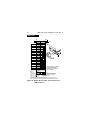
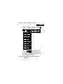
Set Drive ID
Look at Figures 3a, 3b or 3c. If your new drive will be the only
hard drive, assign it as "Drive ID 0," which requires no drive ID
jumpers installed. If your new drive is to be a second hard drive,
assign it as "Drive ID 1" by placing one of the extra jumper
plugs supplied in the enclosed plastic bag (one of the larger
plugs) on the "Drive ID 1" position, as shown in the figure. Do
not remove cover from area shown shaded in the figure.
Double check drive ID settings for your drive or drives.
12
Hawk 2XL Family Installation Guide, Rev. C
_______________________________________________________________________________________________________________________
Table 1. Drive configuration selections summary
Model
Type
N
N
N
W
W
W
WC
WC
WC
--Function
J1
Drive ID
Drive Activity LED
Option select
Drive ID
Drive Activity LED
Option select
Drive ID
Y[6]
Drive Activity LED Y[3]
Option select:
Delayed Mtr Start Y[2]
Enable Mtr Start Y[2]
Write Protect
Parity Disable
Connector --J6 J1-Aux J2
X,Y none
X,[3] none
none X
X,Y X,Y[5]
Y[3]
X
X,Y none
Y[3] none
none
none
none
none
X
X
X
X
Appl.
Figure
3a
3a
3d
3b,3c[1]
3b
3d
3b[4]
3b[4]
3e
3e
3e
3e
Hawk 2XL Family Installation Guide, Rev. C
13
_______________________________________________________________________________________________________________________
("X" means the function selection can be made with jumpers on
that connector;
"Y" means the signal is available to host through that connector).
Notes[ ] for Table 1:
[1] Use either J6 or J1-Aux, but not both.
[2] I/O connector J1 plugs directly into host. No jumper can be
installed on J1. The host supplies the logic state of these
function signals; causing the selection of these functions.
[3] The host can drive a remotely located Drive Activity LED
using this signal.
[4] Use either J1 or J6, but not both.
[5] Jumper plugs can be used on J1-Auxiliary pins 1-2, 3-4, 56 and 7-8 to set drive ID if desired, but usually a connector/
cable is plugged to J1-Auxiliary to run these signals to the
host for remote ID selection.
[6] The host selects drive ID through J1.
14
Hawk 2XL Family Installation Guide, Rev. C
_______________________________________________________________________________________________________________________
Select Operating Features
If your new drive replaces an existing drive, you must set up
the new drive to operate as the old drive did. Check the documentation for your old drive to see how the drive was set to
operate. Look at Figure 3d or 3e. Normally, you should leave
off the "Delay Motor Start", "Enable Motor Start," "Write Protect", "Parity Disable" and "Term power to SCSI Bus" jumpers.
A jumper on means the feature is enabled, except for "Parity
Disable," where a jumper on means that parity checking is disabled. Only "Terminator Enable" and "Term Power from drive"
jumper positions should have a jumper on ("N" and "W" models only). Do not remove these two default jumpers or add jumpers to any of the other jumper positions mentioned above unless your computer system documentation indicates otherwise.
The factory installed default settings are generally always correct.
Hawk 2XL Family Installation Guide, Rev. C
15
_______________________________________________________________________________________________________________________
Drive model "WC" plugs directly into a bulkhead or PCB
mounted connector. Systems using these drives have made
provisions for terminators and selecting most options, so only
"Write Protect" and "Parity Disable" options (on J2) must be
considered for possible setting by a person installing a replacement drive (usually no change is needed). Most systems using
"WC" model drives use drives that have unique drive internal
control firmware, so "off the distributor shelf" drives probably
will not work in these installations. Firmware cannot be changed
on these drives. If you are upgrading by installing an additional
drive, consult the system documentation or system purchase
source for help in setting up drive ID, options and getting termination correct.
I/O line terminators
The SCSI I/O lines must be "terminated" at the drive connected
to the end of the cable. If your new drive is a model "N" or "W"
and is to be connected at the end of the cable, a jumper plug
should be installed on J2 (one of the smaller plugs) at the location shown in Figure 3d where it says "Terminator Enable."
On J2, the "Terminator Power" (TP) jumper should be left in the
"Term. Power From Drive" position, unless otherwise directed
by your computer documentation.
16
Hawk 2XL Family Installation Guide, Rev. C
_______________________________________________________________________________________________________________________
If your drive is to be connected at the cable connector that is
not at the end of the cable (it is a second hard drive for your
system), the "Terminator Enable" jumper should not be installed.
Remove and store the jumper if there is one on the "Terminator
Enable" position.
If installing a "WC" model drive see system documentation.
"WC" drives have no terminators, nor do they furnish terminator power to the I/O bus. Terminators are in the Host system.
Hawk 2XL Family Installation Guide, Rev. C
17
_______________________________________________________________________________________________________________________
N drives
Drive
Front
Jumper Plug
(enlarged to
show detail)
J6
Pin 1
PCB
LRR
Reserved E E E
D S S A2A1A 0
SCSI ID = 0
(default)
SCSI ID = 1
SCSI ID = 2
SCSI ID = 3
SCSI ID = 4
SCSI ID = 5
SCSI ID = 6
SCSI ID = 7
Remote LED
11
Do not remove 12
cover or install
any jumpers
Drive Activity
LED
CATH
Figure 3a. Model "N" drive ID Select and LED
connection
18
Hawk 2XL Family Installation Guide, Rev. C
_______________________________________________________________________________________________________________________
W/WC drive
Pin 1
J6
PCB
Reserved
A3 A2 A1A0
SCSI ID = 0
(default)
SCSI ID = 1
SCSI ID = 2
Drive
Front
SCSI ID = 3
SCSI ID = 4
SCSI ID = 5
SCSI ID = 6
SCSI ID = 7
SCSI ID = 8
Jumper Plug
(enlarged to
show detail)
SCSI ID = 9
PCB
SCSI ID = 10
SCSI ID = 11
SCSI ID = 12
SCSI ID = 13
SCSI ID = 14
Shipped with cover installed.
Do not install jumpers;
retain cover unless 20 pin
plug is installed.
SCSI ID = 15
Host
Alternate
Usage Plug:
Reserved Pins
+5V
Drive Activity LED
11 9 7 5 3 1
8 6 4 2
Ground
Optional connections to
switching circuits in host
equipment to establish
drive ID.
Dashed area is optional host circuitry (external to the drive) connected to
host supplied optional usage plug. Do not connect anything to pins 13-20.
Figure 3b. Model "W" and "WC" drive ID select and
LED connection
Hawk 2XL Family Installation Guide, Rev. C
19
_______________________________________________________________________________________________________________________
W drives
68 Pin SCSI I/O
+5V
Connector
Ground
Pin 1
J1-Auxiliary
Pin 1A
4P
J1-DC Power
3P2P
Drive
HDA
Rear
1P
J1
SCSI ID = 0
PCB
SCSI ID = 1
SCSI ID = 2
SCSI ID = 3
SCSI ID = 4
SCSI ID = 5
SCSI ID = 6
SCSI ID = 7
SCSI ID = 8
SCSI ID = 9
SCSI ID = 10
SCSI ID = 11
SCSI ID = 12
SCSI ID = 13
SCSI ID = 14
SCSI ID = 15
A 3 A 2 A 1A 0
11 9 7 5 3 1
Host Alternate
Usage Plug:
+5V
N.C.
8
Ground
6
4
2
Optional connections to switching
circuits in host equipment to
establish drive ID. Pins 2, 4, 6,
and 8 are driven low for 250 ms
after PWR ON and reset to
allow jumper selectable SCSI ID.
Dashed area is optional host circuitry (external to the drive)
connected to host supplied optional usage plug.
Figure 3c. Model "W" drive ID select and LED
connection
20
Hawk 2XL Family Installation Guide, Rev. C
_____________________________________________________________________________________________________________
N/W drives
Drive Front
Drive PCB
Jumper Plug
(enlarged to
show detail)
J2
Jumper
Positions
Terminator Enable
R
T D MW P E T T
E S E P D S P P
(default)
Delay Motor Start
Enable Motor Start
Write Protect
Parity Disable
Term. Power from Drive
(default)
Term. Power to SCSI Bus
Term. Power from SCSI Bus
Figure 3d. Models "N" and "W" drive configurator,
option select
Hawk 2XL Family Installation Guide, Rev. C
21
___________________________________________________________________________________________________________________
WC drives
Drive Front
Drive
PCB
Jumper Plug
(enlarged to
show detail)
J2
Jumper
Positions
R
T D MW P E T T
E S E P D S P P
Delay Motor Start
Enable Motor Start
Write Protect
Parity Disable
* Not used.
Figure 3e. Model "WC" drive configurator,
option select
22
Hawk 2XL Family Installation Guide, Rev. C
_______________________________________________________________________________________________________________________
Mounting the drive
Important Precautions:
• Make sure your computer is turned off before beginning installation.
• Although switched off, your computer must remain plugged
into an electrical outlet with an earth ground. This minimizes
the possibility of damage from static discharge.
• Static electrical charges can accumulate quickly on people,
clothing and synthetic materials. The electrostatic fields due
to these charges when brought in close proximity to susceptible circuit assemblies and components, can result in degraded reliability or immediate failure of the affected component or assembly.
• Always wear a grounded wrist strap. Attach the wrist strap to
the metal chassis of your computer. Use the antistatic pad as
your work surface, and avoid installation in areas with staticinducing carpets.
1.
Begin by removing the cover of the computer. Follow the
instructions in your computer manual. Systems that use
"WC" drives probably do not require cover removal, as the
drives are mounted in a module that slides into place and
plugs in.
Hawk 2XL Family Installation Guide, Rev. C
23
_______________________________________________________________________________________________________________________
2.
Does your system have 5.25-inch drive bays?Your Seagate
drive is designed to fit into a 3.5-inch wide drive bay. If
your computer has 5.25-inch drive bays, then you must
mount the drive ("N" or "W" models only) in a conversion
frame kit before then you must mount the drive ("N" or "W"
models only) in a conversion frame kit before it will fit into
your computer. Purchase a conversion frame kit from your
computer dealer if necessary.
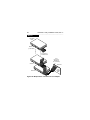
3.
Connect the 50 or 68 pin interface cable to the hard drive
interface connector on the SCSI host adapter card. Be
careful not to bend the pins on the host adapter card connector. Refer to your SCSI host adapter manual for the
location of the interface connector.
The sockets on the interface cable must be matched correctly with the pins on your SCSI host adapter interface
connector. Verify the location of pin 1 on the SCSI host
adapter using your computer system's manual. Pin 1 on
the interface cable is indicated by the stripe along the edge
of the cable. Plug the cable into the hard drive interface
connector on your SCSI host adapter.
4.
Thread the other end of the interface cable through your
drive bay and connect to the disc drive, as shown in Figure 4a, 4b, 4c or 4d.
The sockets on the interface cable must be matched correctly with the pins on the disc drive. Pin 1 on the interface
cable is indicated by the strip along the edge of the cable;
24
Hawk 2XL Family Installation Guide, Rev. C
_______________________________________________________________________________________________________________________
pin 1 on the Seagate disc drive is the pin closest to the
HDA, on the side closest to the four-pin powersupply connector as shown in Figure 4a or 4b. Plug the interface cable
into the drive connector firmly but carefully. The connector
should cover both rows of pins.
If you are installing a second or multiple disc drives, repeat this procedure using the additional drive connectors
on the interface cable, as shown in Figures 4c or 4d.
5.
Mount the drive in a drive bay.
• Direct mounting:
The disc drive can be mounted in the drive bay in any
orientation permitted by the drive bay mechanical configuration. Be careful not to over tighten the mounting
screws. Screws must not extend into the side drive
mounting holes more than 0.015 inches, (9/64 inches)
or into the bottom mounting holes 0.20 inches (3/16
inches). Purchase the four required 6-32 x 1/4 inch
screws at a hardware or drive supplier store. If needed,
Figure 6 shows the drive mounting dimensions.
• Using drive rails:
In some computers, you must attach drive rails to either
side of the drive, then slide the drive into the drive bay
on its drive rails. Be sure that the drive is securely
mounted within the bay. In computers that do not use
drive rails, screw the drive or the frame kit holding the
drive directly to the drive bay.
Hawk 2XL Family Installation Guide, Rev. C
25
_______________________________________________________________________________________________________________________
• Using a conversion frame kit:
To mount a 3.5" drive in a 5.25" drive bay, install the
drive in the frame kit (installation instructions and required hardware are included with a frame kit). Then
mount the frame kit in the drive bay.
If you are installing two disc drives, repeat the appropriate procedure above for the second drive.
• Using a special module:
"WC" drives should be fitted with slides or most likely,
mounted in a special module that slides into the host
equipment.
• Drive activity LED:
If the drive mounts such that the drive activity LED does
not show when the computer cover is on, the computer
may provide for a remote LED two conductor cable to
be used on all models. This cable plugs into J6 on the
front of the drive as shown in Figure 3a.
"WC" model drives have a line available in the J1-80 pin
interface. Check system documentation to see if J1 signal is used or if a cable should be attached to J6.
26
Hawk 2XL Family Installation Guide, Rev. C
___________________________________________________________________________________________________________________
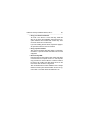
50-pin drive
HDA
Pin 1
*
* Illustrates "N" model I/O
Figure 4a. Fifty-pin I/O connection to drive
68-pin drive
HDA
Pin 1
Figure 4b. Sixty-eight pin connection to drive
Hawk 2XL Family Installation Guide, Rev. C
27
_______________________________________________________________________________________________________________________
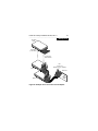
Multiple drive
“N” Model
Drive
SCSI ID 6
(or last drive)
2 through 6
SCSI devices
Pin 1
(check your
adapter for Pin 1 location)
SCSI ID 1
SCSI ID 7
SCSI ID 0
Host
Adapter
PCB
Figure 4c. Multiple drive connection to host adapter
28
Hawk 2XL Family Installation Guide, Rev. C
_______________________________________________________________________________________________________________________
W drive
“W” Model
Drive
SCSI ID 15
(or last drive)
2 through 15
SCSI devices
Pin 1
(check your
adapter for
Pin 1 location)
SCSI ID 1
SCSI ID 7
SCSI ID 0
Host
Adapter
PCB
Figure 4d. Multiple-drive connection to host adapter
Hawk 2XL Family Installation Guide, Rev. C
29
_______________________________________________________________________________________________________________________
WC drive
Note: This drive model plugs directly into a backplane
connector and therefore uses no cables.
Figure 4e. Drive model "WC" with single 80 pin
connector
30
Hawk 2XL Family Installation Guide, Rev. C
_______________________________________________________________________________________________________________________
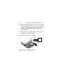
6.
Attach a system power cable to the power connector on
each drive as shown in Figure 5. If your system does not
have an extra power cable for the hard drive, you can
purchase a Y-shaped power cable, such as the one
shown in Figure 2.
7.
Review each of the previous steps to verify that you have
completed the installation correctly.
8.
Replace the cover on your computer.
DC Power
Connector
4 3 2 1
Pin
1
2
3
4
Power
Cable
Figure 5. Power connection to drive
Power
+12V
+12V ret
+ 5V ret
+ 5V
Hawk 2XL Family Installation Guide, Rev. C
31
_______________________________________________________________________________________________________________________
[4]
C
[3]
G
L
D
[1]
F
E
A
Notes:
[1] Mounting holes three on each side,
6-32 UNC. Max screw length into side
of drive 0.15 in. (3.81 mm). Screw
tightening torque 6.0 in-lb (.675 NM)
max with minimum thread engagement
of 0.12 in. (3.05 mm).
[2] Mounting holes four on bottom, 6-32
UNC. Max screw length into bottom of
drive 0.20 in. (5.08 mm). Screw
tightening torque 6.0 in-lb (.675 NM)
max with minimum thread engagement
of 0.12 in. (3.05 mm).
[3] Power and interface connectors can
extend past the "A" dimension by
0.040 in. (1.02 mm).
[4] Decorative front panel (optional).
[5] Mounting hole locations same for all
Hawk 2XL models.
B
J
[2]
H
A
B
C
D
E
F
G
K
P
N
[4]
M
H
J
K
L
M
N
P
Inches
5.74 ± .010
4.00 ± .010
1.00 + .021
– .009
2.362 ± .010
.620 ± .020
4.000 ± .010
.250 + .010
– .005
1.750 ± .010
3.750 ± .010
2.370 ± .020
1.00 ± .010
4.000 ± .010
0.19 ± .010
0.015 max
Millimeters
145.80 ± .25
101.60 ± .25
25.40 + .53
– .22
60.00 ± .25
15.75 ± .50
101.60 ± .25
6.35 + .25
– .12
44.45 ± .25
95.25 ± .25
60.20 ± .50
25.4 ± .25
101.6 ± .25
4.83 ± .25
0.381 max
Figure 6. Mounting configuration dimensions
32
Hawk 2XL Family Installation Guide, Rev. C
_______________________________________________________________________________________________________________________
Configuring the computer for your drive
The hardware part of your installation should now be complete.
Software installation informs your computer operating software
about your Seagate disc drive characteristics. You can then
divide your drive into partitions called "logical drives."
DOS Installation
To install your Seagate disc drive in your computer software,
your computer operating system should be Microsoft DOS version 4.0 or higher. Your SCSI adapter card must be able to
address greater than two gigabytes.
If you already have a hard disc drive on your computer and you
are installing a second drive, now is a good time to evaluate
the status and quality of your backups. Once you are satisfied
with the status of your backups, then proceed.
Caution.
Determine which drive is to be partitioned in a two
drive system.
• Turn your computer on and boot-up from your existing hard
drive or from a diskette in drive A, whichever is applicable.
Watch the screen for text that tells which key(s) to press to
branch into the system setup program. Hit CTL-ALT-DEL to
boot-up again if you missed it. Choose to go into setup.
Hawk 2XL Family Installation Guide, Rev. C
33
_______________________________________________
• Setup presents a menu. Choose the menu item that asks
you to declare the drive type. If the screen says the drive
type is "not installed" or something similar, save that and leave
setup. If it asks you to enter a drive type, enter "none," "drive
not installed," "type 0" or whatever similar response is given
as a choice on the menu.
• Save and leave this screen. The computer will probably boot
up again. If not, hit CTL-ALT-DEL.
• At the C> prompt or A> prompt, run the FDISK utility program either from your existing hard drive or from a diskette in
drive A. (refer to your DOS user's Reference Manual for more
detailed instructions on FDISK procedures).
• A menu comes up that gives choices pertaining to installing
your new drive and dividing it into partitions. If the drive you
set the jumpers for is Drive ID 0 (no ID jumpers on), the menu
will stay at the top, "Current fixed disk drive: 1"
• From the menu choose "Create a DOS partition..."
• Proceed to set up desired partitions.
• If your new drive is jumpered as Drive ID 1, choose "Select
next fixed disk drive" on the menu. FDISK displays the main
menu again, but at the top it says "Current fixed disk drive:
2".
• The menu displayed gives you the same opportunity as mentioned above to partition your second drive as several logical
(simulated) drive volumes.
34
Hawk 2XL Family Installation Guide, Rev. C
_______________________________________________________________________________________________________________________
Caution. Do not try to change the partitions set up for an existing in-use drive. If you change any partitions or
logical (simulated) drive assignments on your existing drive, you will lose all data stored. Always backup
the existing drive's data on diskettes, tape, or other
media before changing the drive's configuration.
The first hard drive (drive jumpered as ID 0) is always called
drive C. If you already have a hard drive, FDISK shows it as
drive C and shows if it has been divided into a primary DOS
partition and an extended partition. The extended partition can
be divided into several logical drives. FDISK lists these logical
drives as D, E, F, etc. The primary DOS partition has the operating system on it (this is the start up or "Boot-up" partition).
From the main menu, choose to set "Active" the DOS partition
you want to boot from, which is the primary DOS partition.
Many people like to make drive C a few megabytes, devoted
almost entirely to the operating system (DOS or other) and little
else.
They put other programs on other logical drives, grouped in
categories that provide a distribution of data and programs
across all logical drives that suits their applications. When satisfied with the set up as instructed in the menus presented,
reboot the drive.
Hawk 2XL Family Installation Guide, Rev. C
35
_______________________________________________________________________________________________________________________
Formatting
Caution.
Do not format the existing drive that contains user data that
you don't want to lose, as all user data will be lost when a drive
is formatted.
When a second drive is installed, the drive letters assigned by
DOS to the first drive may change. Be careful not to accidently
format a logical drive with existing data.
When you complete drive partitioning, you need to high-level
format every new logical drive you have set up. If your new
drive is to be the boot-up drive, insert the DOS system diskette
in drive A and type at the A/> prompt FORMAT C: /s/v. This
formats drive C and puts the programs on that are necessary
to boot the computer from the C drive, and verifies that the
format was performed correctly. For each additional logical drive
you have changed or newly set up, type in FORMAT X: /v (where
"X" is the proper drive letter for the drive to be formatted).
36
Hawk 2XL Family Installation Guide, Rev. C
_______________________________________________________________________________________________________________________
Note:
Seagate Technology assumes no liability for lost user data.
From the C/> prompt, try to switch to each logical drive (C:, D:,
E:, etc.) to see if you can get a prompt for each logical drive
(C\>, D\>, E\>, etc.). With each prompt that you select, type
CHKDSK. This shows if the logical drives are usable for storing
data and programs. If the logical drives you set up are not recognized, try the FDISK set up routine and FORMAT again. You
may have made a small mistake at some point in the installation procedure.
Make sure that the total capacity shown for your new drive is
equal (or close to) the formatted capacity given in the Product
Information table, column B at the end of this guide. If not, you
may need to get a newer SCSI adapter card that allows you to
access the complete drive.
If the complete DOS operating system software is not on your
primary DOS drive (usually C), read it in from diskettes on drive
A.
Hawk 2XL Family Installation Guide, Rev. C
37
_______________________________________________________________________________________________________________________
Macintosh installation
To configure this drive in a Macintosh system, you must use a
third-party hard disc initialization application. Most software vendors and computer stores that carry Macintosh software will
have hard disc drivers available for purchase.
Follow the instructions provided with the disc initialization application to complete the installation of your Seagate drive.
Note.
The Apple HD SC Setup utility included with your Macintosh
system software only works on drives ordered directly
through Apple.
Unix installation
There are several versions of the Unix operating system. Each
of these handle hard disc installation in a different manner. For
this for reason, refer to your system's operation manual for information about how to complete the installation of this disc
drive. Contact Seagate Technical support services for any additional information needed to install the drive in a Unix system.
38
Hawk 2XL Family Installation Guide, Rev. C
__________________________________________________________________________________________________________________
Troubleshooting
Before calling Seagate Technical Support, please read and
consider the possibilities discussed below. The suggestions
presented here will resolve the majority of installation problems.
General installation troubleshooting
• Check system compatibility. This is a SCSI interface device. Check your system documentation to ensure that is
supports SCSI interface devices.
• Check the drive ID assigned. Model "N" has three drive ID
jumper positions on the drive. See Figure 3a. Models "W" and
"WC" have four drive ID jumper positions. See Figures 3b and
3c.
• Check the drive operating feature jumpers. See Figure 3b
and associated explanations.
Hawk 2XL Family Installation Guide, Rev. C
39
_______________________________________________________________________________________________________________________
• Check to ensure that drive is receiving power. Insert the
drive into your system. Listen carefully for the sound of the
drive motor spinning up. There should be the rotational spin
up noise, with no interruption, followed by seeking noises and
clicks. If the drive motor does not spin up, check the power
supply. If your power supply is functioning properly, but the
drive does not spin up, contact the company from which you
purchased the drive. If you have added one or more drives to
your existing system the power supply may not be able to
furnish enough power. Check with your drive purchase source
about this.
Inadequate power supplies may work for a short period of
time under great stress, and then either fail or operate in a
severely degraded mode. It may supply enough +5 V for the
logic to respond, but not enough current on the +12 V for a
spinup.
40
Hawk 2XL Family Installation Guide, Rev. C
_______________________________________________________________________________________________________________________
Product repair information
Service requirements
The special facilities required for the manufacture of these
drives generally prohibit repair in the field. If problems occur
during installation, please contact your supplier for assistance.
Do not attempt to disassemble or repair. Drives should be sent
to the repair depot through the purchase source, if possible.
Please observe the following cautions.
Caution.
• Handle drive with care. Do not drop, or bump hard.
• Never remove the cover of these disc drives. Servicing items
in the sealed HDA (heads, media, actuator, etc.) require
special facilities. The drive contains no user purchasable
parts or PCBs.
• Opening the sealed HDA voids the drive warranty.
• Applying a soldering device to the components on the PCB
voids the drive warranty.
• Do not connect or disconnect cables without first removing
power from the drive.
• Place drive on a flat, static dissipative surface and handle with
extreme care. Always follow all EOS/ESD precautions to
avoid damage to the electrical assemblies.
Hawk 2XL Family Installation Guide, Rev. C
41
_______________________________________________________________________________________________________________________
Product repair and return information
Seagate customer service centers are the only facilities authorized to service Seagate drives. Seagate does not sanction any
third-party repair facilities. Any unauthorized repair or tampering with the factory-seal voids the warranty.
Shipping: When transporting or shipping a drive, a Seagate
approved container must be used. Keep your original box. They
are easily identified by the Seagate Approved Package label.
Shipping a drive in a non-approved container voids the drive
warranty.
Seagate repair centers may refuse receipt of components
improperly packaged or obviously damaged in transit. Contact
your Authorized Seagate Distributor to purchase additional
boxes. Seagate recommends shipping by an air-ride carrier
experienced in handling computer equipment.
Warranty: Contact your Seagate Authorized Distributor, Dealer
or other purchase source for warranty information.
If the drive is no longer under warranty contact purchase source
for repair information or refer to numbers listed in section
Technical Support Services.
42
Hawk 2XL Family Installation Guide, Rev. C
________________________________________________________________________________________________________________________
Technical support services
Seagate Technology provides technical support literature and
diagnostic utilities to Authorized Distributors. Please contact
your dealer for technical support and installation troubleshooting. Product Technical Support is available for all Seagate
products by calling the SeaFAX, SeaFONE, SeaTDD or
SeaBOARD services. These are toll calls.
1.
SeaBOARD™: the Seagate Technical Support Bulletin
Board System (BBS) is available by modem 24 hours a
day, 7 days a week. SeaBOARD provides access to:
• Specifications and configurations for all Seagate products
• Reprints of Seagate documentation
• A directory of information and useful utilities that can be
downloaded to your computer
To access SeaBoard:
• Set your communications software to eight data bits, no parity,
and one stop bit (8-N-1).
• Dial the nearest SeaBOARD number from the following list:
Hawk 2XL Family Installation Guide, Rev. C
43
_______________________________________________________________________________________________________________________
BBS
location
Modem
number
Maximum
baud rate
Australia
England
France
Germany
Korea
Singapore
USA
Thailand
61-2-756-2359
44-62-847-8011
33-1-40-67-1034
49-89-140-9331
82-2-556-7294
65-292-6973
408-438-8771
662-531-8111
9600
9600
9600
9600
9600
9600
9600
9600
2.
CompuServe: Online technical support for Seagate Products is available on CompuServe. Type "Go Seagate" to
access our technical support forum.
3.
SeaFAX™: You can use a touch-tone telephone to access
Seagate's automated FAX system and receive technical
support information by return FAX. This service is available
24 hours daily. To reach SeaFAX dial:
PHONE 408/438-2620 (USA)
PHONE 44-62-847-7080 (England)
4.
Seagate Technical Support FAX:
You can FAX specific questions or comments to Seagate
technical support specialists 24 hours daily. Responses
are FAXed between 8:00 a.m. and 5:00 p.m. (Pacific time),
Monday through Friday. To reach Seagate Technical Support Fax dial:
FAX 408/438-8137
44
Hawk 2XL Family Installation Guide, Rev. C
5.
SeaFONE™: Technical support specialists are available
to answer questions by telephone from 8:00 a.m. to 5:00
p.m. (Pacific time), Monday through Friday. The SeaFONE
enhanced phone system also provides recorded technical
information on selected Seagate products whenever callers are placed on hold. This recorded information is accessible 24 hours daily. To reach SeaFONE dial:
_______________________________________________
PHONE 408/438-8222
6.
SeaTDD™: Using a Telecommunications Device for the
Deaf (TDD), you can send questions or comments 24 hours
a day, and communicate with a Seagate technical support
specialist between 8:00 a.m. and 5:00 p.m. (Pacific time),
Monday through Friday. To reach SeaTDD dial:
TDD 408/438-5382
Hawk 2XL Family Installation Guide, Rev. C
45
_______________________________________________________________________________________________________________________
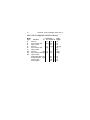
Hawk 2XL Family product information
Characteristics of the various drives covered by this manual are
listed in the following table.
Legend for table column meanings:
A = capacity, unformatted Gigabytes
B = capacity, formatted Gigabytes [1]
C = number of cylinders, user accessible
D = number of heads
E = + 5 V typical current [2], Amps
F = +12 V typical current [2], Amps
G = spindle speed r/min +0.5% tolerence
Model
A[3]
B
C[3] D
E
F
ST32151N
2.54 2.148 4176 8 0.65 0.40
ST32151W 2.54 2.148 4176 8 0.65 0.40
ST32151WC 2.54 2.148 4176 8 0.65 0.40
ST31051N
1.26 1.060 4176 4 0.65 0.40
ST31051W 1.26 1.060 4176 4 0.65 0.40
ST31051WC 1.26 1.060 4176 4 0.65 0.40
ST32155N
2.54 2.148 4176 8 0.65 0.40
ST32155W 2.54 2.148 4176 8 0.65 0.40
ST32155WC 2.54 2.148 4176 8 0.65 0.40
ST31055N
1.26 1.060 4176 4 0.65 0.40
ST31055W 1.26 1.060 4176 4 0.65 0.40
ST31055WC 1.26 1.060 4176 4 0.65 0.40
G
5411
5411
5411
5411
5411
5411
5411
5411
5411
5411
5411
5411
46
Hawk 2XL Family Installation Guide, Rev. C
_______________________________________________________________________________________________________________________
Notes.
[1] Standard units are factory formatted with 512 data bytes
per sector with 10 spare sectors per cylinder for ST32151/
ST32155, 5 spare sectors per cylinder for ST31051/
ST31055 and 2 cylinders at inner tracks reserved for
spares in addition to capacity listed. All spare sectors are
on one track.
[2] Measured with an average reading DC ammeter. Instantaneous +12 V current peaks will exceed these values.
[3] Preliminary values.
Seagate Technology, Inc.
920 Disc Drive, Scotts Valley, CA. 95066-4544, USA
Publication Number: 77767490, Rev. C
Printed in USA