1
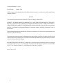
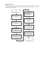
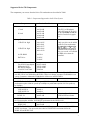
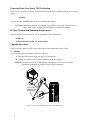
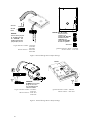
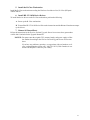
Series 700 Workstation to B–Class Workstation Upgrade Procedures Part No. A4190–90013 Edition E1096 Hewlett–Packard Company 3404 East Harmony Rd., Fort Collins CO 80525 1 Hewlett-Packard Co. 1996 First Printing: October 1996 UNIX is a registered trademark in the United States and other countries, licensed exclusively through X/Open Company Limited NOTICE The information contained in this document is subject to change without notice. HEWLETT–PACKARD MAKES NO WARRANTY OF ANY KIND WITH REGARD TO THIS MATERIAL INCLUDING BUT NOT LIMITED TO THE IMPLIED WARRANTIES OF MERCHANTABILITY AND FITNESS FOR A PARTICULAR PURPOSE. Hewlett-Packard shall not be liable for errors contained herein or for incidental or consequential damages in connection with the furnishing, performance or use of this material. Hewlett-Packard assumes no responsibility for the use or reliability of its software on equipment that is not furnished by Hewlett-Packard. This document contains proprietary information which is protected by copyright. All rights reserved. No part of this document may be photocopied, reproduced or translated to another language without the prior written consent of Hewlett-Packard Company. RESTRICTED RIGHTS LEGEND. Use, duplication, or disclosure by government is subject to restrictions as set forth in subdivision (c) (1) (ii) of the Rights in Technical Data and Computer Software Clause at DFARS 252.227.7013. Hewlett-Packard Co., 3000 Hanover St., Palo Alto, CA 94304. 10 9 8 7 6 5 4 3 2 1 2 Emissions Regulations Federal Communications Commission (FCC) The Federal Communications Commission of the U.S. government regulates the radio frequency energy emanated by computing devices through published regulations. These regulations specify the limits of radio frequency emission to protect radio and television reception. All HP nodes and peripherals have been tested and comply with these limits. The FCC regulations also require that computing devices used in the U.S. display the agency’s label and that the related documentation include the following statement: NOTICE: This equipment has been tested and found to comply with the limits for a Class A digital device, pursuant to part 15 of the FCC rules. These limits are designed to provide reasonable protection against harmful interference when the equipment is operated in a commercial environment. This equipment generates, uses, and can radiate radio frequency energy and, if not installed and used in accordance with the instruction manual, may cause harmful interference to radio communications. Operation of this equipment in a residential area is likely to cause harmful interference in which case the user will be required to correct the interference at his own expense. Compliance to these regulations requires the use of shielded cables. Canadian Department of Communications (DOC) This digital apparatus does not exceed the Class A limits for radio noise emissions from digital apparatus as set out in the Radio Interference Requirements of the Canadian Department of Communications. Compliance to these regulations requires the use of shielded cables.VCCI Class 1 ITE Emissions Regulations Compliance Any third–party I/O device installed in HP system(s) must be in accordance with the requirements set forth in the preceding Emissions Regulations statements. In the event that a third–party noncompliant I/O device is installed, the customer assumes all responsibility and liability arising therefrom. Compliance to these regulations requires the use of shielded cables. Electrostatic Discharge (ESD) Precautions Electrostatic charges can damage the integrated circuits on printed circuit boards. To prevent such damage from occurring, observe the following precautions when unpacking and installing the board. D D D D D Stand on a static–free mat. Wear a static strap to ensure that any accumulated electrostatic charge discharges from your body to ground. Connect all equipment together, including the static–free mat, static straps, routing nodes, and peripheral units. Keep uninstalled printed circuit boards in their protective antistatic bags. Once you have removed the printed circuit boards from their protective antistatic bags, handle them by their edges. 3 Warnings and Cautions WARNING: Removing device cover may expose sharp edges in equipment chassis. To avoid injury, use care when installing customer add– on devices WARNUNG: Das Entfernen der Geräteabdeckung legt die scharfen Kanten im Inneren des Gerätes frei. Um Verietzungen zu vermeiden, seien Sie vorsichtig beim Einbau von zusätzlichen Bauteilen, die vom Kunden selber eingebaut werden können AVERTISSEMENT: Des bords tranchants du châssis de l’équipement peuvent être exposés quand le cache de l’unité n’est pas en place. Pour éviter des blessures, faire très attention lors de l’installation de modules supplémentaires par le client. WARNING: Disconnect power plug from wall outlet or source power before moving or removing the device, or installing add–on components. WARNUNG: Entfernen Sie die Stromzuführung von der Steckdose oder der Stromquelle bevor Sie das Gerät bewegen, abbauen, oder zusätzliche Bauteile installieren. AVERTISSEMENT: Débrancher la fiche de la prise de courant ou de la source d’alimentation électrique avant de déplacer ou de retirer l’unité, ou avant d’installer des modules supplémentaires. CAUTION: System power cord must be plugged into an accessible dedicated ac mains receptacle. VORSICHT: Das System–Netzanschlußkabel muß an eine zugängliche spezielle Wechselstrom–Hauptzuführungssteckdose angeschlossen werden. ATTENTION: Le fil d’alimentation électrique du système doit être branché dans une prise de courant c.a. spécialisée accessible. 4 700 Series Workstation to B–Class Workstation Trade–Up Installation Instructions. These instructions document the installation of a B–Class workstation when trading up from your 700 Series workstation. The procedures you perform may vary depending on the configuration of your Series 700 workstation. The installation procedures are divided into the following areas: D Removing components from your Series 700 workstation that can be used in the B–Class workstation. D Installing components from your Series 700 workstation into the B–Class workstation. D Power up the B–Class workstation CAUTION: Although the chances of corrupting your system are very small, you must back up your system, before you shut down your system to perform this upgrade, . NOTICE:The B–Class workstation is shipped with an adapter cable (HP Part Number 8120–6861). This cable is used to adapt a DB–15 type video cable to the built– in graphics EVC connector. Customers upgrading a Series 700 with an RGB to RGB video cable will need to order a RGB to DB–15 video cable (HP Part Number C2300–60005). 5 Upgrade Overview An overview of the 700 Series to B–Class Workstation Trade–up Installation procedures are shown in the following flowchart. Depending on your upgrade hardware and software configuration you may not have to complete all of these procedures. Start Follow the installation procedures in the B–Class Owners Guide (A4190–90014) Shutdown your Series 700 workstation Power up your B–Class workstation Power down your Series 700 workstation Install HP–UX 10.20 drivers (if applicable) Remove the components from the Series 700 workstation to be used in the B–Class workstation Install compnents from the Series 700 workstation into the B–Class workstation (See Table 1) Return the Series 700 workstation to HP per the return instructions at the end of this procedure End 6 Supported Series 700 Components The components you can use from the Series 700 workstation are described in Table 1 Table 1 Components Supported in the B–Class System Component Product/Part Number Comments Monitors 17 inch A4330A/B A4032A/B 20 inch A4331A/B A2094A/B A4033A/B The EVC to DB adapter cable ((HP ppart# 8120–6861)) i to t connectt the th monitor it to t is the B–Class built–in graphics. Storage Devices 1 GB SE 1in. high 9164–0395 0950–2601 0950–3037 2 GB SE 1in. high 0950–2606 0950–3039 4x CD–ROM A4326A DAT Drive C1503C C1504C EISA Cards Fast SCSI–2 host adapter Differential SCSI HP–IB host adapter 10/100VG LAN Link Only one drive can be added to the B–Class workstation. It cannot be configured as g th boot b t drive d i and d mustt bbe the installed in the second disk bay. As a result, a CD–ROM or DDS drive cannot be installed. A2679–66001 25525–60002 25560–60001 J2645AA NOTICE: For the 10/100 LAN Link J2655AA you must order options AAU and APZ to unlock HP–UX 10.20 CD Media kit B3782EA. There is no charge. Assumes CD–ROM drive on system. Customers without the CD Media kit will have to order B3782EA. X.25 link J2159A NOTICE: For the X.25 interface to support HP–UX 10.20 you must order J2793A with performance option #100 for speeds up to 64Kbps or performance option #101 for speeds up to 256Kbps. Graphics Cards VISUALIZE–8 VISUALIZE–24 HCRX–8 HCRX–24 A4441A A4442A A4070A/B A4071A/B Must install a A4242A VISUALIZE accelerator. NOTICE: The HCRX–8/24 are NOT supported without the A4242A VISUALIZE Accelerator. You must order A4242A VISUALIZE Accelerator for the HCRX–8/24 HCRX–8Z HCRX–24Z A4079A/B A4179A/B Must exchange accelerator NOTICE: The HCRX–8Z and HCRX–24Z are NOT supported without the A4242A VISUALIZE Accelerator. You must order the A4443A VISUALIZE Accelerator kit for the HCRX–8Z and HCRX–24Z 7 Powering Down Your Series 700 Workstation Before you power down your Series 700 workstation, check the type of graphics cards in your system by typing: graphinfo You will need this information when you are performing this upgrade. CAUTION: Although the chances of corrupting your system are very small, you must back up your system, before you shut your system down, to perform this upgrade. B–Class Workstation Minimum Requirements Ensure that the B–Class workstation, you are upgrading to, has a minimum of: 64MB ram 2GB internal disk with HP–UX 10.20 installed Upgrade Procedures These are the procedures for removal and replacement of the components listed in Table 1 1. Monitor To remove and replace the monitor perform the following: A. Disconnect the monitor from your Series 700 workstation. B. Connect the monitor to the B–Class workstation as shown in Figure 1. NOTICE: You must use the EVC to DB Adapter Cable (HP part# 8120–6861) to connect the monitor to the built–in graphics in the B–Class workstation. EVC to DB Adapter Cable 8120–6861 Figure 1. Connecting the Monitor on the B–Class Workstation 8 2. Internal Storage Devices To remove and replace the internal storage devices perform the following: A. To remove an internal storage devices from your Series 700 system refer to your Series 700 Owners Guide. B. The hard disk jumper settings are shown in Figure 2, Figure 3, and Figure 4. Ensure the jumpers on your disk drive are set to the appropriate configuration. LED Front View J3 SCSI ID 1 2 3 4 5 6 7 8 9 10 Second 5 Drive NOTICE: If applicable change the SCSI ID to 5 as shown Do not change any other jumpers Quantum Disk Drive Models – VP32210 VP31110 DEC Disk Drive Model – DSP3107LS HP Part Number – 9164–0395 SCSI ID Second 5 Drive Hewlett-Packard Disk Drive Models – C3324A C3325A HP Part Numbers – 0950–2601 0950–2606 Figure 2. Internal Storage Device Jumper Settings C. The CD ROM drive jumper settings are shown in Figure 5. Ensure the jumpers on your CD ROM drive are set to the appropriate configuration. D. To install the internal storage device(s) in your B–Class workstation, refer to Figure 6 and the Model B132L/B160L Owner’s Guide (A4190–90014). NOTICE:When using a hard disk from your Series 700 workstation, it cannot be configured as the boot drive and must be installed in position 2 (front position). 9 LED SCSI ID Second Drive 1 2 34 56 5 NOTICE: A0, A1 and A3 are the SCSI ID jumpers. The jumpers TE, SS, WS and I/O should be removed. The jumper EP and INT should be in place NOTICE: The first three jumpers (1, 2, and 3) should be removed. The SCSI ID jumpers are jumpers 4, 5, and 6. SCSI ID 5 Seagate Disk Drive Models – ST32430N ST31230N ST31200N HP Part Numbers – 0950–2601 0950–2606 Quantum Disk Drive Model – LPS1080S HP Part Number – 9164–0395 Figure 3. Internal Storage Device Jumper Settings FRONT J6 J2 Term Power from Drive SCSI ID 5 CAUTION Do NOT use the jumper plugs for J2 on J6. You will damage the internal contacts Seagate Disk Drive Models – ST31051N ST32151N HP Part Numbers – 0950–3037 0950–3039 Quantum Disk Drive Model – FB1050S HP Part Number – 0950–3037 Figure 4. Internal Storage Device Jumper Settings 10 M S B L S B A2 A1 A0 M S B A0 A1 A2 SCSI ID 5 L S B SCSI-2 Terminators (must be removed) Jumpers Target ID Default Jumpers NOTICE: SCSI ID 6 is the default for root and is NOT recommended for CD-ROM drive 2 CD ROM Drive HP Part Number A4325–60001 or A3416–60001 Figure 5. CD–ROM Jumper Settings Figure 6. Installing a Hard Disk Drive in Postion 2 (Front Position) in your B–Class Workstation 11 3. EISA Cards To remove and replace any of EISA cards, perform the following: A. To remove an EISA card from your Series 700 system refer to your Series 700 Owners Guide. B. To install an EISA card in your B–Class workstation see Figure 7, and refer to the Model B132L/B160L Owner’s Guide (A4190–90014). NOTICE:The X.25 link and the 10/100VG LAN Link require HP–UX 10.20 drivers to be installed. 4. Graphics Cards To remove and replace any of the graphic cards, perform the following: A. To remove a graphic card from your Series 700 system refer to your Series 700 Owners Guide. B. To install a graphic card in your B–Class workstation see Figure 7, and refer to the Model B132L/B160L Owner’s Guide (A4190–90014). NOTICE: The HCRX–8Z and HCRX–24Z are NOT supported without the A4242A Accelerator. You must order the A4443A Accelerator kit, remove and send back the A4072A accelerator card. Install the new A4242A accelerator card you received in the A4443A accelerator kit. Figure 7. Installing Option Cards in Your B–Class Workstation 12 5. Install the B–Class Workstation Install the B–Class workstation according the Hardware Installation Card, B–Class (HP part# A4190–90010) 6. Install HP–UX 10.20 Device Drivers To install the device drivers on the B–Class workstation, perform the following: A. Power up the B–Class workstation B. To install the HP–UX 10.20 Device Drivers the instructions and the Release Notes that accompany the drivers. 7. Return All Unused Parts Follow the instructions in the Hewlett–Packard Upgrade Return Instructions sheet (part number A1658–90611) included in the Upgrade Return Kit. NOTICE: You must return the original CPU, memory boards, and power supply to Hewlett–Packard according to the Hewlett–Packard Upgrade Return Instructions sheet. If you have any problems, questions , or suggestions with our hardware, software, or documentation, please call 1–888–301–5932 (US & Canada) or contact the HP Response Center for your country. 13 Part Number: A4190–90013 Printed in U.S.A. Edition E1096 14