1
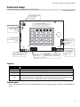
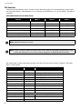
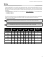
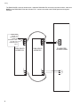
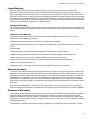
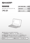
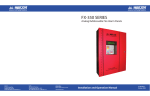
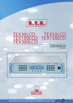
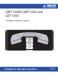
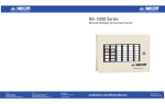
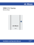
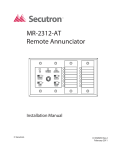
Advanced Life Safety Solutions
Advanced Life Safety Solutions
RAM-300LCD Series
Remote Annunciator
System Normal
18:01 MON 2007-04-05
SYSTEM
RESET
SIG N AL
SIL EN CE
A.C. O N
1
ALARM
S UPV
2
TRBL
3
EN TER
ABC
FIRE
D RIL L
4
BUZZER
SIL EN CE
7
L AMP
TEST
*
G HI
PRS
5
J KL
8
0
TUV
QZ
CPU FAIL
DEF
6
MEN U
MNO
9
CAN CEL
W XY
#
IN FO
FA-300 SERIES
Remote Annunciator
......
. . ... . . . . . . . . . .. . .
. . . . . . . ... . .. . . .. . .
. . .... . . . . .. . . .! . " ... . . .
. .. ##.
U.S.A.
60 Industrial Parkway
Cheektowaga, NY 14227
Tel: 1-888-660-4655 Fax: 1-888-660-4113
© Mircom 2005
Printed in Canada
Subject to change without prior notice
. . . .. .. . . . .. . .
Installation and Operation Manual
LT-1002 Rev. 4 082207
August 2007
RAM-300LCD Installation and Operation Manual
Contents
Introduction .............................................................................................................................. 1
Mechanical Installation............................................................................................................ 2
Functional Setup ...................................................................................................................... 3
Jumpers ................................................................................................................................ 3
Potentiometer........................................................................................................................ 3
DIP Switches......................................................................................................................... 4
Wiring ........................................................................................................................................ 5
Specifications & Features ....................................................................................................... 7
Enclosure .............................................................................................................................. 7
Electrical Specifications ........................................................................................................ 7
Current Drain for Battery Calculations .................................................................................. 7
Operating Instructions............................................................................................................. 8
Warranty.................................................................................................................................... 9
i
RAM-300LCD Installation and Operation Manual
Introduction
The RAM-300LCD is a remote annunciator used for the FA-300 Series and FX-350/351 Series Fire Alarm Panels. It
provides remote access to the fire alarm panel.
Note: Configuration of the FA-300 Series and FX-350/351 Series fire alarm panels from this remote
annunciator is not allowed.
The RAM-300LCD has an LCD display, common feature LEDs and pushbuttons, as well as an alpha numeric
keypad for the LCD.
The RAM-300LCD comes complete with an enclosure and can be surface mounted.
7.7"
SYSTEM NORMAL
18:01 MON 2003-04-05
SYSTEM
RESET
A.C. ON
SIGNAL
SILENCE
1
FIRE
DRILL
4
BUZZER
SILENCE
7
LAMP
TEST
*
ALARM
SUPV
2
GHI
PRS
5
8
0
ABC
JKL
TUV
QZ
TRBL
3
6
9
DEF
MNO
WXY
#
FA-300 SERIES
Remote Annunciator
CPU FAIL
ENTER
7.2"
MENU
CANCEL
INFO
1.25"
Each RAM-300LCD has its own address. Addresses available are 1 to and including 7. The buttons on the left side
may be individually disabled if required, by setting DIP Switch SW31, see Functional Setup section following.
This annunciator may be selected to operate as an ancillary device using DIP Switch SW31-6 to disable all buttons
except, Lamp Test, Buzzer Silence, Info and Arrow Buttons.
Note: This ancillary device option, if selected takes priority over any other selections made on DIP Switch
SW31.
1
Mechanical Installation
Mechanical Installation
To mount the RAM-300LCD open the front door, remove the dead front plate and mount the backbox to the wall
using the four screws provided. This enclosure may also be mounted to a 4” square electrical box. There are two
conduit areas provided at the bottom center of the enclosure. With the dead front plate removed, you may do the
functional setup and wiring before replacing the dead front, see following sections.
7.5"
6.0"
7.0
FOUR
MOUNTING
HOLES
5.9"
1.22"
2
RAM-300LCD Installation and Operation Manual
Functional Setup
POTENTIOMETER FOR
LCD CONTRAST
ADJUSTMENT
VR1
SYSTEM NORMAL
JW1, JW2, JW3 ARE
FOR FACTORY USE
LEAVE JUMPERS
JW2 AND JW3 IN
PLACE.
18:01 MON 2007-04-05
JW1
JW2
A.C. ON
JW3
SYSTEM
RESET
P2
SIGNAL
SILENCE
1
FIRE
DRILL
4
BUZZER
SILENCE
7
LAMP
TEST
*
THESE PINS ARE
FOR FACTORY USE
ONLY
ALARM
SUPV
2
GHI
PRS
5
8
0
ABC
JKL
TUV
QZ
TRBL
3
6
DEF
MNO
CPU FAIL
ENTER
MENU
9
CANCEL
#
INFO
WXY
P1
24V IN/OUT
- +
JW8
SW30
ON
ON
1 2 3 4 5 6 7 8
RS-485 IN/OUT
+
S
1 2 3 4
SW31
CUT JUMPER JW8 TO
MAKE RAM-300LCD AN
ANCILLARY DEVICE.
SW31 DIP Switch
for various
system functions
THIS
CONNECTOR IS
FOR FACTORY
USE ONLY
SW30 DIP Switch for annunciator
address setting. Valid addresses
1 to 7.
Place the 120 ohm
EOL resistor between
+ and - terminals of
the RS-485 on the
last annunciator
only.
Jumpers
Jumper
Jumper Function
JW1
FACTORY USE ONLY (JUMPER OFF)
JW2
FACTORY USE ONLY (JUMPER INSTALLED)
JW3
FACTORY USE ONLY (JUMPER INSTALLED)
JW8
CUT jumper to set the RAM-300LCD as an ancillary device. Use NP-2051 blank labels to
cover the System Reset, Signal Silence, Fire Drill, Enter, Menu and Cancel buttons for the
Ancillary Device Feature. Only Buzzer Silence, Lamp Test and Info are used.
Potentiometer
VR1 is a potentiometer used for LCD contrast adjustment and is located in the top left corner of the RAM-300LCD
board.
3
Functional Setup
DIP Switches
There are two DIP switches to be set. SW30 is found at the bottom right corner of the board and is used to select
the annunciator address. Valid addresses are 1 to 6 inclusive for FA-300 Series, 1 to 7 for FX-350/351. Set address
as follows:
RAM-300LCD Address DIP Switch Setup
Address
SW30-1
SW30-2
SW30-3
1
ON
OFF
OFF
2
OFF
ON
OFF
3
ON
ON
OFF
4
OFF
OFF
ON
5
ON
OFF
ON
6
OFF
ON
ON
7 (FX-350/351)
ON
ON
ON
Note: SW30-4 DIP switch is not used.
Note: For the FX-350/351 Series Fire Alarm Panels, if the number of annunciators programmed is 5, then
the first five addresses (1 to 5 inclusive) must be assigned to the RAM-300LCD annunciators.
DIP switch SW31 is found at the bottom left hand corner and is used to select a number of features. DIP switch
SW31 is set as follows:
DIP Switch SW31
Position
1
ON
Disable System Reset Button
1
OFF
Enable System Reset Button
2
ON
Disable Signal Silence Button
2
OFF
Enable Signal Silence Button
3
ON
Disable Fire Drill Button
3
OFF
Enable Fire Drill Button
4
ON
Disable Lamp Test Button
4
OFF
Enable Lamp Test Button
5
ON
Disable Buzzer Silence Button
5
OFF
Enable Buzzer Silence Button
6
NOT USED
7
ON
16 bit checksum (for FX-350/351 panels)
7
OFF
8 bit checksum (for FA-300 Series panels)
8
4
Function
NOT USED
RAM-300LCD Installation and Operation Manual
Wiring
To wire the RAM-300LCD, you must first remove the dead front plate. Wire from the last RAM-300LCD to the next
RAM-300LCD and so on; then from the first RAM-300LCD to the Fire Alarm Panel. There are only two connections
to be made, one for power and the RS-485 loop. Replace the dead front plate once all functional setup and wiring
is complete.
The RS-485 Wiring to the RAM-300LCD is recommended to be Twisted Shielded Pair. The wire gauge may be
• 22 AWG up to 2000 ft.
• 20 AWG up to 4000 ft.
The 24V DC field wiring needs to be of an appropriate gauge for the number of annunciators and the total wiring run
length. See Current Drain for Battery Calculations on page 7 and calculate the Maximum current for all
annunciators summed together.
Note: All circuits are power limited and must use type FPL, FPLR or FPLP Power Limited Cable.
CAUTION: Accidentally connecting any of the 24V DC wires to the RS-485 wiring will result in damage to
the Annunciator and/or to the Fire Alarm Control Panel to which it is connected.
Total Maximum
Current for all
Annunciators
Maximum Wiring Run to Last Annunciator
18AWG
16AWG
14AWG
12AWG
Max. Loop
Resistance
Amperes
ft
m
ft
m
ft
m
ft
m
Ohms
0.12
1180
360
1850
567
3000
915
4250
1296
15
0.30
470
143
750
229
1200
366
1900
579
6
0.60
235
71
375
114
600
183
850
259
3
0.90
156
47
250
76
400
122
570
174
2
1.20
118
36
185
56
300
91
425
129
1.5
1.50
94
29
150
46
240
73
343
105
1.2
1.70
78
24
125
38
200
61
285
87
1.0
5
Wiring
FA-300 FIRE
ALARM PANEL
+
AUX
SUPPLY
-
-
RS-485 IN/OUT
S
+
- 24V IN/OUT +
S
- 24V IN/OUT +
-
RAM-300LCD
ADDRESS 1
+
6
RAM-300LCD
ADDRESS 2
R S -4 8 5
MAKE SURE
THERE IS A
120 OHM E.O.L.
RESISTOR
BETWEEN + AND ON THE LAST
ANNUNCIATOR
ONLY
RS-485 IN/OUT
- +
S
The RAM-300LCD is wired as shown below. Additional RAM-300LCDs are wired in the same manner, make sure
ONLY the last RAM-300LCD has the 120 ohm E.O.L. resistor connected to the RS-485 positive and negative
terminals.
RAM-300LCD Installation and Operation Manual
Specifications & Features
Enclosure
Enclosure may be mounted on a 4” square electrical box or on a wall.
Electrical Specifications
• 24 VDC nominal voltage
• LCD Display, Pushbutton Controls and LED indicators.
• Local Buzzer, Indicators (AC-On, Alarm, Supervisory, Trouble and CPU Fail), and Controls (System Reset,
Signal Silence, Fire Drill, Buzzer Silence and Lamp Test,).
• Annunciation of up to 16 Points.
• Not Expandable.
• Standby 16 mA Max., Alarm 40mA Max. All LEDs illuminated 40 mA Max.
Current Drain for Battery Calculations
The maximum normal current drain will be during Lamp Test when all lamps are illuminated on one chassis at a
time. Thus the currents are:
• Normal Standby
=
16 mA
• Maximum
=
40 mA
The Normal Standby Current is used for battery size calculations (see the FA-300 Series or FX-350/351 Series
Fire Alarm Control Panel manual for battery calculations) and includes the current drain for the Trouble Buzzer,
Trouble LED, and one Alarm LED. The Maximum Current is used to calculate the wire size (see Wiring section
above).
7
Operating Instructions
Operating Instructions
Normal: All indicators are normally OFF except for the green A.C. ON light which illuminates steadily.
Alarm: Operate Alarm Initiating Devices to activate Indicating Appliances. Signals will sound, common alarm will
illuminate red.
Silencing of Alarm: Press Signal Silence button momentarily to silence all audible signals.
Note: The signal silencing function may be inhibited for up to one minute. The Signal silence button will not
operate until the inhibit period has expired.
Waterflow: Indicating appliances and other output circuits that are activated in response to an alarm initiated by a
designated Waterflow Zone cannot be silenced (manual or automatic).
Supervisory: Activation of any initiating devices for supervisory will sound the buzzer continuously. The Common
supervisory indicator will illuminate amber (steady). The Common Supervisory indicator remains "ON" when the
buzzer is silenced.
System Reset: Press the Reset button momentarily to restore normal operation. All alarm indicators will extinguish
& all latched functions are restored.
Trouble: Any system trouble will sound the buzzer intermittently and common Trouble indicator will flash amber
until the fault is corrected. Specific types of trouble will be indicated by the LCD display by pressing the INFO button.
Call for service.
Fire Drill: Press the Fire Drill button momentarily to sound all audible signals without initiating an alarm. Press the
button again for normal system operation. Note: Auxiliary relays will not operate when Fire Drill is operated.
Lamp Test: Press the Lamp Test button momentarily to test all indicators. All indicators should be lit and buzzer will
sound. Holding down this button will display the firmware version.
CPU Fail LED: Will illuminate amber for an onboard CPU error.
Menu Button: Press the Menu button to access the associated FA-300 Series Fire Alarm Panel. The Menu button
operates as it does on the main FA-300 Series Fire Alarm Panel, refer to the fire alarm manual for further
explanation. Use the keypad arrow keys (2, 4, 6 and 8) to scroll through the menu. Configuration of the fire alarm
panel cannot be accessed from the RAM-300LCD. The Menu button does not operate for the FX-350/351 Series
Fire Alarm Panels.
Enter, Cancel and Info Buttons: The Enter and Cancel buttons are used to input and erase some data for the fire
alarm panel and the Info button is used to view the fire alarm panel logs. The Enter and Cancel buttons do not
operate for the FX-350/351 Series Fire Alarm Panels.
Keypad: The numbered keys and/or letter keys function as they do at the FA-300 Series Fire Alarm Panel, refer to
the fire alarm manual for further explanation. The keypad does not operate for the FX-350/351 Series Fire Alarm
Panels.
8
RAM-300LCD Installation and Operation Manual
Warranty & Warning Information
Warning Please Read Carefully
Note to End Users: This equipment is subject to terms and conditions of sale as follows:
Note to Installers
This warning contains vital information. As the only individual in contact with system users, it is your responsibility to
bring each item in this warning to the attention of the users of this system. Failure to properly inform system endusers of the circumstances in which the system might fail may result in over-reliance upon the system. As a result,
it is imperative that you properly inform each customer for whom you install the system of the possible forms of
failure.
System Failures
This system has been carefully designed to be as effective as possible. There are circumstances, such as fire or
other types of emergencies where it may not provide protection. Alarm systems of any type may be compromised
deliberately or may fail to operate as expected for a variety of reasons. Some reasons for system failure include:
•Inadequate Installation
A Fire Alarm system must be installed in accordance with all the applicable codes and standards in order to provide
adequate protection. An inspection and approval of the initial installation, or, after any changes to the system, must
be conducted by the Local Authority Having Jurisdiction. Such inspections ensure installation has been carried out
properly.
•Power Failure
Control units, smoke detectors and many other connected devices require an adequate power supply for proper
operation. If the system or any device connected to the system operates from batteries, it is possible for the
batteries to fail. Even if the batteries have not failed, they must be fully charged, in good condition and installed
correctly. If a device operates only by AC power, any interruption, however brief, will render that device inoperative
while it does not have power. Power interruptions of any length are often accompanied by voltage fluctuations which
may damage electronic equipment such as a fire alarm system. After a power interruption has occurred,
immediately conduct a complete system test to ensure that the system operates as intended.
•Failure of Replaceable Batteries
Systems with wireless transmitters have been designed to provide several years of battery life under normal
conditions. The expected battery life is a function of the device environment, usage and type. Ambient conditions
such as high humidity, high or low temperatures, or large temperature fluctuations may reduce the expected battery
life. While each transmitting device has a low battery monitor which identifies when the batteries need to be
replaced, this monitor may fail to operate as expected. Regular testing and maintenance will keep the system in
good operating condition.
•Compromise of Radio Frequency (Wireless) Devices
Signals may not reach the receiver under all circumstances which could include metal objects placed on or near the
radio path or deliberate jamming or other inadvertent radio signal interference.
•System Users
A user may not be able to operate a panic or emergency switch possibly due to permanent or temporary physical
disability, inability to reach the device in time, or unfamiliarity with the correct operation. It is important that all
system users be trained in the correct operation of the alarm system and that they know how to respond when the
system indicates an alarm.
•Automatic Alarm Initiating Devices
Smoke detectors, heat detectors and other alarm initiating devices that are a part of this system may not properly
detect a fire condition or signal the control panel to alert occupants of a fire condition for a number of reasons, such
as: the smoke detectors or heat detector may have been improperly installed or positioned; smoke or heat may not
be able to reach the alarm initiating device, such as when the fire is in a chimney, walls or roofs, or on the other side
9
Warranty & Warning Information
of closed doors; and, smoke and heat detectors may not detect smoke or heat from fires on another level of the
residence or building.
•Software
Most Mircom products contain software. With respect to those products, Mircom does not warranty that the
operation of the software will be uninterrupted or error-free or that the software will meet any other standard of
performance, or that the functions or performance of the software will meet the user’s requirements. Mircom shall
not be liable for any delays, breakdowns, interruptions, loss, destruction, alteration or other problems in the use of a
product arising our of, or caused by, the software.
Every fire is different in the amount and rate at which smoke and heat are generated. Smoke detectors cannot
sense all types of fires equally well. Smoke detectors may not provide timely warning of fires caused by
carelessness or safety hazards such as smoking in bed, violent explosions, escaping gas, improper storage of
flammable materials, overloaded electrical circuits, children playing with matches or arson.
Even if the smoke detector or heat detector operates as intended, there may be circumstances when there is
insufficient warning to allow all occupants to escape in time to avoid injury or death.
•Alarm Notification Appliances
Alarm Notification Appliances such as sirens, bells, horns, or strobes may not warn people or waken someone
sleeping if there is an intervening wall or door. If notification appliances are located on a different level of the
residence or premise, then it is less likely that the occupants will be alerted or awakened. Audible notification
appliances may be interfered with by other noise sources such as stereos, radios, televisions, air conditioners or
other appliances, or passing traffic. Audible notification appliances, however loud, may not be heard by a hearingimpaired person.
•Telephone Lines
If telephone lines are used to transmit alarms, they may be out of service or busy for certain periods of time. Also the
telephone lines may be compromised by such things as criminal tampering, local construction, storms or
earthquakes.
•Insufficient Time
There may be circumstances when the system will operate as intended, yet the occupants will not be protected from
the emergency due to their inability to respond to the warnings in a timely manner. If the system is monitored, the
response may not occur in time enough to protect the occupants or their belongings.
•Component Failure
Although every effort has been made to make this system as reliable as possible, the system may fail to function as
intended due to the failure of a component.
•Inadequate Testing
Most problems that would prevent an alarm system from operating as intended can be discovered by regular testing
and maintenance. The complete system should be tested as required by national standards and the Local Authority
Having Jurisdiction and immediately after a fire, storm, earthquake, accident, or any kind of construction activity
inside or outside the premises. The testing should include all sensing devices, keypads, consoles, alarm indicating
devices and any other operational devices that are part of the system.
•Security and Insurance
Regardless of its capabilities, an alarm system is not a substitute for property or life insurance. An alarm system also
is not a substitute for property owners, renters, or other occupants to act prudently to prevent or minimize the
harmful effects of an emergency situation.
IMPORTANT NOTE: End-users of the system must take care to ensure that the system, batteries, telephone lines,
etc. are tested and examined on a regular basis to ensure the minimization of system failure.
10
RAM-300LCD Installation and Operation Manual
Limited Warranty
Mircom Technologies Ltd. warrants the original purchaser that for a period of two years from the date of
manufacture, the product shall be free of defects in materials and workmanship under normal use. During the
warranty period, Mircom Technologies Ltd. shall, at its option, repair or replace any defective product upon return of
the product to its factory, at no charge for labor and materials. Any replacement and/or repaired parts are warranted
for the remainder of the original warranty or ninety (90) days, whichever is longer. The original owner must promptly
notify Mircom Technologies Ltd. in writing that there is defect in material or workmanship, such written notice to be
received in all events prior to expiration of the warranty period.
International Warranty
The warranty for international customers is the same as for any customer within Canada and the United States, with
the exception that Mircom Technologies Ltd. shall not be responsible for any customs fees, taxes, or VAT that may
be due.
Conditions to Void Warranty
This warranty applies only to defects in parts and workmanship relating to normal use. It does not cover:
•damage incurred in shipping or handling;
•damage caused by disaster such as fire, flood, wind, earthquake or lightning;
•damage due to causes beyond the control of Mircom Technologies Ltd. such as excessive voltage, mechanical
shock or
•water damage;
•damage caused by unauthorized attachment, alterations, modifications or foreign objects;
•damage caused by peripherals (unless such peripherals were supplied by Mircom Technologies Ltd.);
•defects caused by failure to provide a suitable installation environment for the products;
•damage caused by use of the products for purposes other than those for which it was designed;
•damage from improper maintenance;
•damage arising out of any other abuse, mishandling or improper application of the products.
Warranty Procedure
To obtain service under this warranty, please return the item(s) in question to the point of purchase. All authorized
distributors and dealers have a warranty program. Anyone returning goods to Mircom Technologies Ltd. must first
obtain an authorization number. Mircom Technologies Ltd. will not accept any shipment whatsoever for which prior
authorization has not been obtained. NOTE: Unless specific pre-authorization in writing is obtained from Mircom
management, no credits will be issued for custom fabricated products or parts or for complete fire alarm system.
Mircom will at its sole option, repair or replace parts under warranty. Advance replacements for such items must be
purchased.
Note: Mircom Technologies Ltd.’s liability for failure to repair the product under this warranty after a reasonable
number of attempts will be limited to a replacement of the product, as the exclusive remedy for breach of warranty.
Disclaimer of Warranties
This warranty contains the entire warranty and shall be in lieu of any and all other warranties, whether expressed or
implied (including all implied warranties of merchantability or fitness for a particular purpose) And of all other
obligations or liabilities on the part of Mircom Technologies Ltd. neither assumes nor authorizes any other person
purporting to act on its behalf to modify or to change this warranty, nor to assume for it any other warranty or liability
concerning this product.
This disclaimer of warranties and limited warranty are governed by the laws of the province of Ontario, Canada.
11
Warranty & Warning Information
Out of Warranty Repairs
Mircom Technologies Ltd. will at its option repair or replace out-of-warranty products which are returned to its factory
according to the following conditions. Anyone returning goods to Mircom Technologies Ltd. must first obtain an
authorization number. Mircom Technologies Ltd. will not accept any shipment whatsoever for which prior
authorization has not been obtained.
Products which Mircom Technologies Ltd. determines to be repairable will be repaired and returned. A set fee which
Mircom Technologies Ltd. has predetermined and which may be revised from time to time, will be charged for each
unit repaired.
Products which Mircom Technologies Ltd. determines not to be repairable will be replaced by the nearest equivalent
product available at that time. The current market price of the replacement product will be charged for each
replacement unit.
WARNING: Mircom Technologies Ltd. recommends that the entire system be completely tested on a regular
basis. However, despite frequent testing, and due to, but not limited to, criminal tampering or electrical
disruption, it is possible for this product to fail to perform as expected.
NOTE: Under no circumstances shall Mircom Technologies Ltd. be liable for any special, incidental, or
consequential damages based upon breach of warranty, breach of contract, negligence, strict liability, or
any other legal theory. Such damages include, but are not limited to, loss of profits, loss of the product or
any associated equipment, cost of capital, cost of substitute or replacement equipment, facilities or
services, down time, purchaser’s time, the claims of third parties, including customers, and injury to
property.
MIRCOM MAKES NO WARRANTY OF MERCHANTABILITY OR FITNESS FOR A PARTICULAR PURPOSE
WITH RESPECT TO ITS GOODS DELIVERED, NOR IS THERE ANY OTHER WARRANTY, EXPRESSED OR
IMPLIED, EXCEPT FOR THE WARRANTY CONTAINED HEREIN.
12
Notes
Advanced Life Safety Solutions
Canada
25 Interchange Way
Vaughan, ON L4K 5W3
Tel: 905-660-4655 Fax: 905-660-4113
U.S.A.
60 Industrial Parkway PMB 278
Cheektowaga, NY 14227
Tel: 1-888-660-4655 Fax: 1-888-660-4113
© Mircom 2007
Printed in Canada
Subject to change without prior notice
www.mircom.com