1
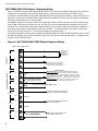
Advanced Life Safety Solutions
QMT-5300A, QMT-5302 and
QZT-5302
Firefighters’ Telephone System
COMMON TEL.
TROUBLE
MASTER TEL.
TROUBLE
INCOMING
CALL
CONNECT/
CLEAR ALL
LAMP
TEST
Installation & Operation Instructions
LT-674 Rev. 2
Dec 2007
QMT-5300A, QMT-5302 and QZT-5302 Installation and Operation Instructions
QMT-5300A, QMT-5302 and QZT-5302 Instructions
Introduction
MIRCOM’s Fire Fighters’ Telephone may be used either alone as a Single Zone System (using the QMT-5300A or
QMT-5302 Master Telephone by itself), or as a Multi-Zoned System (with the QZT-5302 Zone Adders).
Mounting
The modules mount in any of the BB-1000 Series Remote Annunciator enclosures except for the QMT-5302 Master
Telephone which mounts into a BB-5008 or BB-5014 backbox. For the QMT-5300A Master Telephone, the included
extended window module must be installed in place of the existing window. In any BB-1000 enclosure, the QMT5300A is mounted bottom-most, and one to five QZT-5302s above, for a total of 60 Telephone Zones. In any BB5008 enclosure, the QMT-5302 should be mounted below the QZT-5302s and beside the master telephone for ease
of ribbon cable installation.
Labels
Two slide-in labels are supplied with the QMT-5300A ; the NP-735 is used for Single Zone and the NP-736 for MultiZone. Slide-in label NP-896 is provided with the QMT-5302, use the Connect for Single Zone or Clear All label for
Multi-Zone. The QZT-5302 includes blank labels for Telephone Zone information.
Chassis Ground
Connect one of the BB-1000 Series Backbox, BB-5008 or BB-5014 Earth-Ground points (Chassis Ground) to Earth
Ground (cold water pipe).
Power Supply
Only the telephone master QMT-5300A or QMT-5302 module requires power. It can be powered with a 24 VDC,
200 mA external DC power source (filtered or un-filtered, such as 4-wire smoke or auxiliary power from a Fire Alarm
Control Panel), see Fig.1
Jumpers
There are three jumpers on the QMT-5300A and QMT-5302 PCB showing at the top of the black chassis. For a
Single-Zoned System JW1 and JW2 have jumpers installed, JW3 does not. For a Multi-Zoned system with QZT5302s, JW1 & JW2 jumpers are removed, and JW3 is installed. There is one jumper, JW1, on each QZT-5302 Zone
Adder, and a jumper is installed only on the last QZT-5302.
Connectors
On the QMT-5300A and QMT-5302, P1 is used only for Multi-Zoned Systems. P2 is the connection for the Master
Telephone Handset. On the QZT-5302, P1 connects to the QMT-5300A, QMT-5302 or previous QZT-5302, and P2
connects to the next QZT-5302.
1
QMT-5300A, QMT-5302 and QZT-5302 Instructions
QMT-5300A/QMT-5302 Master Telephone Wiring
Figure 1 shows the wiring for QMT-5300A and QMT-5302. A Fire Alarm Control Panel’s Detection Zone (should be
configured as Trouble-Only or Non-Latching Supervisory) is used to annunciate Telephone Trouble. This is
connected to the QMT-5300A or QMT-5302 TROUBLE terminals (polarity does not matter), and the ELR device for
that zone is connected to the QMT-5300A or QMT-5302 ELR terminals. DC Power (24 V DC, filtered or unfiltered at
200 mA) is connected to the 24 V DC terminals.
If the Master Telephone is being used alone as a Single-Zone System, the NP-735 Label is used or Connect label
from NP-896, and Jumpers are placed on JW1 and JW2 only. The one Telephone Zone connects to the TEL-CKT
terminals. The 10 Kohm ELR resistor that is shipped with this unit is connected after the last Remote Telephone on
the Zone and the negative black jumper is removed for Class B. For Class A wiring, remove both red and black
jumper wires and wire from OUT + - to the remote telephones and back to RET + -.
If the Master Telephone is being used as a Multi-Zoned System with QZT-5302s, the NP-736 Label is used or Clear
All label from NP-896, and a Jumper is placed on JW3 only. The TEL-CKT terminals are left as is. Telephone Zone
wiring is done via the QZT-5302s.
Figure 1: QMT-5300A/QMT-5302 Master Telephone Wiring
QMT-5300A or QMT-5302
APPROVED ELR
END- OF-LINE
DEVICE FOR
CONNECTED FIRE
ALARM PANEL
TELEPHONE CIRCUIT
TROUBLE
ELR
TO DETECTION ZONE OF CONNECTED
FIRE ALARM PANEL, TO BE USED TO
ANNUNCIATE TELEPHONE TROUBLE
TRANSMIT
OUT
+
RED
REMOVE BOTH JUMPERS
WHEN WIRING AS CLASS A
RET
+
-
BLK
TELEPHONE CIRCUIT
SINGLE ZONE SYSTEM: CLASS B TELEPHONE ZONE FOR FT-300 OR
OTHER COMPATIBLE REMOTE TELEPHONES. REMOVE THE NEGATIVE
BLACK JUMPER FROM OUT - and RET -TERMINALS. CONNECT A 10K ELR
RESISTOR AFTER THE LAST REMOTE TELEPHONE. FOR CLASS A WIRING
OF TELEPHONE ZONE, WIRE OUT + - AND BACK FROM LAST TELEPHONE
TO RET + -.
MULTI-ZONE SYSTEM: DO NOT CONNECT ANY REMOTE TELEPHONES
AND LEAVE RED AND BLACK WIRES CONNECTED AS SHOWN.
CLASS A RETURN FOR SINGLE ZONE SYSTEM
TO LAMP TEST TERMINAL ON QMP-5100A
OR QMP-5101 AUDIO CONTROL MODULE
LT
LAMP TEST
COM
NOT USED
+
EXT AUDIO
-
TO EXT AUDIO TERMINAL ON QMP-5100A
AUDIO CONTROL MODULE
NOT USED
+
24 VDC
2
-
16 or 18 AWG ONLY
FROM 20.4V DC LOW BATTERY TO 29V
DC UNFILTERED HIGH AC LINE
QMT-5300A, QMT-5302 and QZT-5302 Installation and Operation Instructions
QZT-5302 Zone Adder Wiring
Figure 2 shows the wiring for QZT-5302. The P1 Cable plugs into P1 on the QMT-5300A or QMT-5302 Master
Telephone for the first Zone Adder, or into P2 of the previous Zone Adder for additional Zone Adders. The Jumper
plug is removed from JW1 on each QZT-5302 and placed on the last QZT-5302.
The Telephone Zones connect to telephone circuits marked Out and Ret (return) terminals, numbered from 1 to 12.
The 10 K ohm ELR resistors that are shipped with the panel are moved to the last Remote Telephone on each Zone
(for Class B) and the negative to negative black wire jumper is removed when using class B wiring.
For Class A, each telephone zone is wired out from the OUT + - terminals to the remote telephones and back to
terminals RET + and -. Also for Class A wiring both the red and black wire jumpers found on the positive and
negative terminals of the QZT-5302 are removed.
Note that on each QZT-5302, the associated buttons for Telephone Zones 1 to 12 are numbered left to right, where
Zones 1 to 6 are the top row, and 7 to 12 are the bottom row.
Figure 2: QZT-5302 Zone Adder Wiring
QZT-5302
OUT 1
+
RET 1
TELEPHONE ZONE, WIRE TO FT-300 OR OTHER COMPATIBLE
REMOTE TELEPHONES. CONNECT 10K ELR RESISTOR AFTER
THE LAST REMOTE TELEPHONE FOR CLASS B AND REMOVE
THE BLACK JUMPER FROM OUT - and RET - TERMINALS . FOR
CLASS A WIRING OF TELEPHONE ZONE, WIRE OUT + - AND BACK
FROM LAST TELEPHONE TO RET + -.
+
-
RETURN FOR CLASS A WIRING
NOTE: REMOVE WIRE JUMPERS BETWEEN POSTIVES
AND NEGATIVES WHEN WIRING ZONES AS CLASS A.
FOR CLASS B ONLY THE WIRE JUMPER BETWEEN
NEGATIVES IS REMOVED.
+
OUT 12
RET 12
-
TELEPHONE ZONE, WIRE TO FT-300 OR OTHER COMPATIBLE
REMOTE TELEPHONES. CONNECT 10K ELR RESISTOR AFTER
THE LAST REMOTE TELEPHONE FOR CLASS B AND REMOVE
THE BLACK JUMPER FROM OUT - and RET - TERMINALS . FOR
CLASS A WIRING OF TELEPHONE ZONE, WIRE OUT + - AND BACK
FROM LAST TELEPHONE TO RET + -.
+
-
RETURN FOR CLASS A WIRING
3
QMT-5300A, QMT-5302 and QZT-5302 Instructions
Operation
Single-Zone System
1. When Telephone “Rings” (the local buzzer sounds intermittently, and the Green Incoming Call LED flashes)
press CONNECT to answer.
2. Press CONNECT again to Hang-Up. (Note that the Telephone Zone will Hang-Up automatically if all handsets
on the Zone are placed back On-Hook.)
3. Press LAMP TEST to test all indicators.
Multi-Zone System
1. When any Telephone Zone “Rings” (the local buzzer sounds intermittently, and the Green Zone LED and
Incoming Call LED flash) press that Zone’s Button once to answer. Once any one Zone has been answered,
calls from other Zone will cause that Zone’s Green LED and Incoming Call LED to flash, but the buzzer will not
sound.
2. Press the answered Zone’s button once again to Hang-Up. (Note that the Telephone Zone will Hang-Up
automatically if all handsets on the Zone are placed back On-Hook.)
3. Press the CLEAR ALL button to disconnect all Zones.
4. Press LAMP TEST to test all indicators.
Indicators on QMT-5300A or QMT-5302
• Common Tel. Trouble: This LED will flash amber if there is any Zone or other trouble in the Fire Fighters’
Telephone System.
• Master Tel. Trouble: This LED will flash amber if the Master Telephone handset is disconnected.
• Incoming Call: This LED will flash green if any Telephone Zone has a handset off-hook and unanswered. It will
be steady green if all Telephone Zones with off-hook handsets have been answered.
• Buzzer: The Buzzer will sound intermittently if one, and only one, Telephone Zone has a handset off-hook and
unanswered.
Indicators on QZT-5302
• Telephone Zone Green LED: This LED will flash green if there is any handset off-hook on that Zone, and the
Zone has not been answered by pressing the Zone’s button. Once answered, the LED will be steady green.
• Telephone Zone Amber LED: This LED will flash amber for Trouble if there is an open-circuit fault on that
Zone, such as the End-of-Line Resistor (ELR) being missing, or a wire break.
4
QMT-5300A, QMT-5302 and QZT-5302 Installation and Operation Instructions
Warranty & Warning Information
Warning Please Read Carefully
Note to End Users: This equipment is subject to terms and conditions of sale as follows:
Note to Installers
This warning contains vital information. As the only individual in contact with system users, it is your responsibility to
bring each item in this warning to the attention of the users of this system. Failure to properly inform system endusers of the circumstances in which the system might fail may result in over-reliance upon the system. As a result,
it is imperative that you properly inform each customer for whom you install the system of the possible forms of
failure.
System Failures
This system has been carefully designed to be as effective as possible. There are circumstances, such as fire or
other types of emergencies where it may not provide protection. Alarm systems of any type may be compromised
deliberately or may fail to operate as expected for a variety of reasons. Some reasons for system failure include:
•Inadequate Installation
A Fire Alarm system must be installed in accordance with all the applicable codes and standards in order to provide
adequate protection. An inspection and approval of the initial installation, or, after any changes to the system, must
be conducted by the Local Authority Having Jurisdiction. Such inspections ensure installation has been carried out
properly.
•Power Failure
Control units, smoke detectors and many other connected devices require an adequate power supply for proper
operation. If the system or any device connected to the system operates from batteries, it is possible for the
batteries to fail. Even if the batteries have not failed, they must be fully charged, in good condition and installed
correctly. If a device operates only by AC power, any interruption, however brief, will render that device inoperative
while it does not have power. Power interruptions of any length are often accompanied by voltage fluctuations which
may damage electronic equipment such as a fire alarm system. After a power interruption has occurred,
immediately conduct a complete system test to ensure that the system operates as intended.
•Failure of Replaceable Batteries
Systems with wireless transmitters have been designed to provide several years of battery life under normal
conditions. The expected battery life is a function of the device environment, usage and type. Ambient conditions
such as high humidity, high or low temperatures, or large temperature fluctuations may reduce the expected battery
life. While each transmitting device has a low battery monitor which identifies when the batteries need to be
replaced, this monitor may fail to operate as expected. Regular testing and maintenance will keep the system in
good operating condition.
•Compromise of Radio Frequency (Wireless) Devices
Signals may not reach the receiver under all circumstances which could include metal objects placed on or near the
radio path or deliberate jamming or other inadvertent radio signal interference.
•System Users
A user may not be able to operate a panic or emergency switch possibly due to permanent or temporary physical
disability, inability to reach the device in time, or unfamiliarity with the correct operation. It is important that all
system users be trained in the correct operation of the alarm system and that they know how to respond when the
system indicates an alarm.
•Automatic Alarm Initiating Devices
Smoke detectors, heat detectors and other alarm initiating devices that are a part of this system may not properly
detect a fire condition or signal the control panel to alert occupants of a fire condition for a number of reasons, such
as: the smoke detectors or heat detector may have been improperly installed or positioned; smoke or heat may not
5
Warranty & Warning Information
be able to reach the alarm initiating device, such as when the fire is in a chimney, walls or roofs, or on the other side
of closed doors; and, smoke and heat detectors may not detect smoke or heat from fires on another level of the
residence or building.
•Software
Most Mircom products contain software. With respect to those products, Mircom does not warranty that the
operation of the software will be uninterrupted or error-free or that the software will meet any other standard of
performance, or that the functions or performance of the software will meet the user’s requirements. Mircom shall
not be liable for any delays, breakdowns, interruptions, loss, destruction, alteration or other problems in the use of a
product arising our of, or caused by, the software.
Every fire is different in the amount and rate at which smoke and heat are generated. Smoke detectors cannot
sense all types of fires equally well. Smoke detectors may not provide timely warning of fires caused by
carelessness or safety hazards such as smoking in bed, violent explosions, escaping gas, improper storage of
flammable materials, overloaded electrical circuits, children playing with matches or arson.
Even if the smoke detector or heat detector operates as intended, there may be circumstances when there is
insufficient warning to allow all occupants to escape in time to avoid injury or death.
•Alarm Notification Appliances
Alarm Notification Appliances such as sirens, bells, horns, or strobes may not warn people or waken someone
sleeping if there is an intervening wall or door. If notification appliances are located on a different level of the
residence or premise, then it is less likely that the occupants will be alerted or awakened. Audible notification
appliances may be interfered with by other noise sources such as stereos, radios, televisions, air conditioners or
other appliances, or passing traffic. Audible notification appliances, however loud, may not be heard by a hearingimpaired person.
•Telephone Lines
If telephone lines are used to transmit alarms, they may be out of service or busy for certain periods of time. Also the
telephone lines may be compromised by such things as criminal tampering, local construction, storms or
earthquakes.
•Insufficient Time
There may be circumstances when the system will operate as intended, yet the occupants will not be protected from
the emergency due to their inability to respond to the warnings in a timely manner. If the system is monitored, the
response may not occur in time enough to protect the occupants or their belongings.
•Component Failure
Although every effort has been made to make this system as reliable as possible, the system may fail to function as
intended due to the failure of a component.
•Inadequate Testing
Most problems that would prevent an alarm system from operating as intended can be discovered by regular testing
and maintenance. The complete system should be tested as required by national standards and the Local Authority
Having Jurisdiction and immediately after a fire, storm, earthquake, accident, or any kind of construction activity
inside or outside the premises. The testing should include all sensing devices, keypads, consoles, alarm indicating
devices and any other operational devices that are part of the system.
•Security and Insurance
Regardless of its capabilities, an alarm system is not a substitute for property or life insurance. An alarm system also
is not a substitute for property owners, renters, or other occupants to act prudently to prevent or minimize the
harmful effects of an emergency situation.
IMPORTANT NOTE: End-users of the system must take care to ensure that the system, batteries, telephone lines,
etc. are tested and examined on a regular basis to ensure the minimization of system failure.
6
QMT-5300A, QMT-5302 and QZT-5302 Installation and Operation Instructions
Limited Warranty
Mircom Technologies Ltd. warrants the original purchaser that for a period of two years from the date of
manufacture, the product shall be free of defects in materials and workmanship under normal use. During the
warranty period, Mircom Technologies Ltd. shall, at its option, repair or replace any defective product upon return of
the product to its factory, at no charge for labor and materials. Any replacement and/or repaired parts are warranted
for the remainder of the original warranty or ninety (90) days, whichever is longer. The original owner must promptly
notify Mircom Technologies Ltd. in writing that there is defect in material or workmanship, such written notice to be
received in all events prior to expiration of the warranty period.
International Warranty
The warranty for international customers is the same as for any customer within Canada and the United States, with
the exception that Mircom Technologies Ltd. shall not be responsible for any customs fees, taxes, or VAT that may
be due.
Conditions to Void Warranty
This warranty applies only to defects in parts and workmanship relating to normal use. It does not cover:
•damage incurred in shipping or handling;
•damage caused by disaster such as fire, flood, wind, earthquake or lightning;
•damage due to causes beyond the control of Mircom Technologies Ltd. such as excessive voltage, mechanical
shock or
•water damage;
•damage caused by unauthorized attachment, alterations, modifications or foreign objects;
•damage caused by peripherals (unless such peripherals were supplied by Mircom Technologies Ltd.);
•defects caused by failure to provide a suitable installation environment for the products;
•damage caused by use of the products for purposes other than those for which it was designed;
•damage from improper maintenance;
•damage arising out of any other abuse, mishandling or improper application of the products.
Warranty Procedure
To obtain service under this warranty, please return the item(s) in question to the point of purchase. All authorized
distributors and dealers have a warranty program. Anyone returning goods to Mircom Technologies Ltd. must first
obtain an authorization number. Mircom Technologies Ltd. will not accept any shipment whatsoever for which prior
authorization has not been obtained. NOTE: Unless specific pre-authorization in writing is obtained from Mircom
management, no credits will be issued for custom fabricated products or parts or for complete fire alarm system.
Mircom will at its sole option, repair or replace parts under warranty. Advance replacements for such items must be
purchased.
Note: Mircom Technologies Ltd.’s liability for failure to repair the product under this warranty after a reasonable
number of attempts will be limited to a replacement of the product, as the exclusive remedy for breach of warranty.
Disclaimer of Warranties
This warranty contains the entire warranty and shall be in lieu of any and all other warranties, whether expressed or
implied (including all implied warranties of merchantability or fitness for a particular purpose) And of all other
obligations or liabilities on the part of Mircom Technologies Ltd. neither assumes nor authorizes any other person
purporting to act on its behalf to modify or to change this warranty, nor to assume for it any other warranty or liability
concerning this product.
This disclaimer of warranties and limited warranty are governed by the laws of the province of Ontario, Canada.
7
Warranty & Warning Information
Out of Warranty Repairs
Mircom Technologies Ltd. will at its option repair or replace out-of-warranty products which are returned to its factory
according to the following conditions. Anyone returning goods to Mircom Technologies Ltd. must first obtain an
authorization number. Mircom Technologies Ltd. will not accept any shipment whatsoever for which prior
authorization has not been obtained.
Products which Mircom Technologies Ltd. determines to be repairable will be repaired and returned. A set fee which
Mircom Technologies Ltd. has predetermined and which may be revised from time to time, will be charged for each
unit repaired.
Products which Mircom Technologies Ltd. determines not to be repairable will be replaced by the nearest equivalent
product available at that time. The current market price of the replacement product will be charged for each
replacement unit.
WARNING: Mircom Technologies Ltd. recommends that the entire system be completely tested on a regular
basis. However, despite frequent testing, and due to, but not limited to, criminal tampering or electrical
disruption, it is possible for this product to fail to perform as expected.
NOTE: Under no circumstances shall Mircom Technologies Ltd. be liable for any special, incidental, or
consequential damages based upon breach of warranty, breach of contract, negligence, strict liability, or
any other legal theory. Such damages include, but are not limited to, loss of profits, loss of the product or
any associated equipment, cost of capital, cost of substitute or replacement equipment, facilities or
services, down time, purchaser’s time, the claims of third parties, including customers, and injury to
property.
MIRCOM MAKES NO WARRANTY OF MERCHANTABILITY OR FITNESS FOR A PARTICULAR PURPOSE
WITH RESPECT TO ITS GOODS DELIVERED, NOR IS THERE ANY OTHER WARRANTY, EXPRESSED OR
IMPLIED, EXCEPT FOR THE WARRANTY CONTAINED HEREIN.
8
Advanced Life Safety Solutions
Canada
25 Interchange Way
Vaughan, ON L4K 5W3
Tel: 905-660-4655 Fax: 905-660-4113
U.S.A.
60 Industrial Parkway PMB 278
Cheektowaga, NY 14227
Tel: 1-888-660-4655 Fax: 1-888-660-4113
© Mircom 2007
Printed in Canada
Subject to change without prior notice
www.mircom.com