1
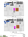
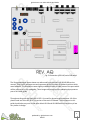
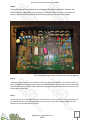
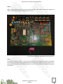
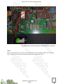
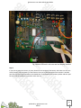
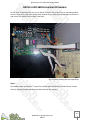
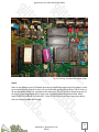
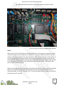
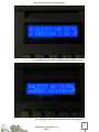
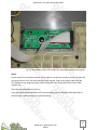
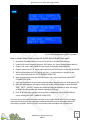
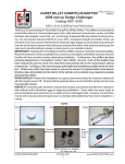
glitchscience.com Alesis HR-16 Mod Guide
1
produced by: glitchscience.com
2012©
glitchscience.com Alesis HR-16 Mod Guide
Table of Contents
Safety........................................................................................................................ p.3
PCB Revision Illustrations........................................................................................... p.4 - 5
Battery Replacement Procedure................................................................................. p.6 - 11
HR-16 to HR-16B Conversion Procedure...................................................................... p.12 - 17
HR-16 / HR-16B Blue LCD Installation.......................................................................... p.18 - 22
HR-16 / HR-16B Factory Pattern Restore Procedure.................................................... p.23 - 25
2
produced by: glitchscience.com
2012©
glitchscience.com Alesis HR-16 Mod Guide
CAUTION!
WARNING ELECTRICAL SHOCK HAZARD
Before servicing unplug the power cord and make sure the electricity is off, this will reduce the risk of
electrical shock. Do not service any equipment if you are unsure about the dangers involved.
PROCEED AT YOUR OWN RISK
ESD (Electrostatic discharge) can damage sensitive electronic components, causing catastrophic
failure. Take preventative measures to reduce the risk of such damages to your equipment.
***************
The author of this guide cannot be held liable for any damages or physical accidents which
could potentially occur during any of the procedures described within this guide.
You are responsible for your own actions.
PROCEED AT YOUR OWN RISK!
3
produced by: glitchscience.com
2012©
glitchscience.com Alesis HR-16 Mod Guide
Fig. 1 Illustration of REV.A main PCB board
Fig. 2 Illustration of REV.CA main PCB board
4
produced by: glitchscience.com
2012©
glitchscience.com Alesis HR-16 Mod Guide
Fig. 3 Illustration of REV.AQ main PCB board
The illustrated images shown above are referenced from the Alesis HR-16/HR-16B service
manual. They are for reference use and represent each of the main PCB board revisions which
were released. The illustrations were slightly modified in order to label some of the parts which
will be referred to in this mod guide. These images are being used for educational purposes as
part of this mod guide.
Throughout this guide the Alesis HR-16 REV. A is used for demonstration purposes. All of the
photos used are of the HR-16 REV.A version of the main PCB board. The procedures in this
guide should also carry over to the other Alesis HR-16 and HR-16B Revisions since they all are
very similar in design.
5
produced by: glitchscience.com
2012©
glitchscience.com Alesis HR-16 Mod Guide
Battery Replacement Procedure
Step 1.
You need to open up the case. To open the case flip your HR-16 over. Locate the four screws
and use a phillips head screw driver to remove those four screws.
Fig. 4 Photo showing the case opened up
Step 2.
Once the screws are removed, to open the case pull up on the back end and push forward. The
top of the case and bottom of the case are connected by several jumper cables. The bottom of
the case holds the main pcb board. The top of the case holds the keyboard pcb board, LCD, and
two slide potentiometers.
6
produced by: glitchscience.com
2012©
glitchscience.com Alesis HR-16 Mod Guide
Step 3.
Disconnect the top from the bottom by unplugging the jumper cables from the main pcb
board. It may be a good idea to take a photo or mark the cables in order to remember the
polarity of each connection before disconnecting them from the main circuit board.
Fig. 5 Photo showing the case opened up and the top removed
Step 4.
Locate the battery. There are three different revisions of the main PCB board. The revisions are REV. A,
REV. CA, and REV. AQ. Shown in Fig are slightly modified illustrations of each of the revisions which were
taken from the service manual. These illustrations show where the battery is located. The battery is the
purple object labeled Batt.
Step 5.
You will need to access the underside of the main PCB board. There are five or so screws which need to
be removed from the main PCB board. Remove these screws using a phillips head screwdriver, then
remove the main PCB board from the case.
7
produced by: glitchscience.com
2012©
glitchscience.com Alesis HR-16 Mod Guide
Fig. 6 Main PCB removed from the case purple battery in the middle
Fig. 7 Main PCB underside
8
produced by: glitchscience.com
2012©
glitchscience.com Alesis HR-16 Mod Guide
Step 6.
Make a note of the battery polarity. You will need know which side is positive and which is negative in
order to solder the new battery holder in place correctly.
Fig. 8 Photo old battery removed from the main PCB
Step 7.
Desolder the old battery. There are many tutorials online on how to effectively desolder a component
from a PCB. I recommend using a desoldering pump along with my soldering iron since I find it to be a
quick and effective means of desoldering, however there are other methods and tools available to get
the job done.
9
produced by: glitchscience.com
2012©
glitchscience.com Alesis HR-16 Mod Guide
Fig. 9 New battery holder and battery installed with correct polarity
Step 8.
Be sure that the polarity of the wires is correct then solder in the new battery holder. Red is positive,
Black is negative. There are lots of soldering tutorials that can be found online.
10
produced by: glitchscience.com
2012©
glitchscience.com Alesis HR-16 Mod Guide
Fig. 10 Main PCB back in the case and new battery installed
Step 9.
If you plan to secure the battery in place, determine the location of the battery and make sure the case
closes properly with the battery in that location. Once you've determined that the location is suitable
peel one side of the tape and adhere the double back to the bottom of the battery holder and then peel
the other side and adhere it in position within the case
11
produced by: glitchscience.com
2012©
glitchscience.com Alesis HR-16 Mod Guide
HR-16 to HR-16B Conversion Procedure
The HR-16 to HR-16B allows the owner of an HR-16 to convert their machine into an HR-16B equivalent.
Since the chips which need to be removed and replaced are not soldered to the board but instead are in
chip sockets, this makes this procedure rather basic.
Fig. 11 Photo showing the case opened up
Step 1.
You need to open up the case. To open the case flip your HR-16 over. Locate the four screws
and use a phillips head screw driver to remove those four screws.
12
produced by: glitchscience.com
2012©
glitchscience.com Alesis HR-16 Mod Guide
Fig. 12 OS chip, U15,and U16 sample chips
Step 2.
Refer to the reference main PCB board illustrations found at the beginning of this guide in order
to locate the OS chip, as well as chips U15 and U16 which are the sample chips. The OS chip is a
28 pin chip which usually has a printed sticker label on it. The U15 and U16 sample chips are 32
pin chips. In the image above the OS chip is the chip labeled with the printed sticker which
reads 'ALESIS 01-04-88 HR-16 V1.06 A671'. Chips U15 and U16 are the two large chips side by
side near the top middle of the image.
13
produced by: glitchscience.com
2012©
glitchscience.com Alesis HR-16 Mod Guide
Fig. 13 Small flat head screw driver used to pry up one end of the OS chip
14
produced by: glitchscience.com
2012©
glitchscience.com Alesis HR-16 Mod Guide
Fig. 14 Small flat head screw driver used to pry up one end of the U16 chip
Fig. 15 OS chip, U15, and U16 sample chips removed
Step 3.
Remove the OS, U15, U16 chips from the main PCB board. It is important to make note of the
orientation of the chip. Each chip has an indentation at one end, make note of this as you will
need to insert the new chips in the same orientation. Each of these chips are in chip sockets, so
no need to desolder or resolder the chips. Use a small screw driver to slowly pry up one end.
Once one end is slightly pryed up, grab the chip at both ends and slowly wiggle it loose and pull
it out. Take your time otherwise you could bend or worse break the pins, so be gentle. Bent
pins can be bent back into place.
Notice in the image above that the empty chip sockets also have an indent at one end to signify
the correct orientation of the chip. Also now that the chips have been removed there is a
silkscreened label. For the OS the label is U11. For the the sample chips the labels as previously
mentioned are U15 and U16.
15
produced by: glitchscience.com
2012©
glitchscience.com Alesis HR-16 Mod Guide
Fig. 16 HR-16B OS chip, U15, and U16 sample chips installed
Step 4.
Carefully insert the new HR-16B conversion chips into their associated chip socket. Make sure
that the orientation of the chip is correct, matching the indentation on the chip with the
indentation on the socket and refer to the noted postion you took in the previous step. The
chips are labeled, be sure to place the OS chip into the 28 pin U11 socket, place the U15 labeled
chip into the 32 pin U15 socket and the U16 labeled chip into the 32 pin U16 socket. Be sure the
chips are properly seated into the sockets.
A side not the labels should not be removed as not only are the labels used to identify the chip
but also used to block the UV window located under the label as to help prevent UV light
entering and altering the contents of the chip.
Now that the new HR-16B conversion chips are installed you can close the case and power up
the machine. Notice that the LCD now reads *ALESIS HR-16:B* as shown in the photo below
and that the soundset is that of the HR-16B. Your HR-16 is now upgraded to an HR-16B
If you want to also load the HR-16B Factory patterns see the section in this guide regarding
loading the factory patterns for the instructions to do so.
16
produced by: glitchscience.com
2012©
glitchscience.com Alesis HR-16 Mod Guide
Fig. 17 Startup screen before HR-16B conversion chips installed
Fig. 18 Startup screen after HR-16B conversion chips installed
17
produced by: glitchscience.com
2012©
glitchscience.com Alesis HR-16 Mod Guide
HR-16 / HR-16B Blue LCD Replacement Installation
Fig. 19 Original HR-16/HR-16B black on orange LCD screen
Fig. 20 Upgraded white on blue HR-16/HR-16B LCD screen
18
produced by: glitchscience.com
2012©
glitchscience.com Alesis HR-16 Mod Guide
Fig. 21 Photo showing the case opened up
Step 1.
You need to open up the case. To open the case flip your HR-16 over. Locate the four screws
and use a phillips head screw driver to remove those four screws.
The top half of the case holds the LCD.
19
produced by: glitchscience.com
2012©
glitchscience.com Alesis HR-16 Mod Guide
Fig. 22 Photo showing the top half of the HR-16 case. LCD is located at the top in the middle
Step 2.
The top half of the case holds the LCD. Locate the LCD. It is connected to one of the gray jumper
cables and is also secured in place by four phillips head screws. It is important at this point to
make note of the orientation of how the cable is plugged into the LCD so that you can plug the
new LCD in correctly. Also make note of which side the LCD header pins are on, so that when
you position the new LCD in place it is correctly oriented in its position.
Now remove the original LCD by unplugging the jumper cable and removing the four screws.
20
produced by: glitchscience.com
2012©
glitchscience.com Alesis HR-16 Mod Guide
Fig. 23 New white on blue LCD installed, fits exact dimensions of the original
Step 3.
Put the new LCD in the same position as the original. Use the four screw to secure it in place. Be
sure that the pins are in the same position as the original. Plug in the jumper cable onto the
LCD. Make sure you plug the jumper cable in using the same orientation that it was on the
origianl LCD.
Close the case and power the unit on.
If you are satisfied with the default LCD contrast setting, you are finished. Otherwise refer to
the next step in order to adjust the contrast setting.
21
produced by: glitchscience.com
2012©
glitchscience.com Alesis HR-16 Mod Guide
Fig. 24 REV.A Main PCB illustration
Step 4. (Optional)
This LCD has been tested to work properly with multiple revisions of the HR-16 and also the HR16B and MMT-8. Revision A boards have an onboard LCD adjustment potentiometer as shown
in the illustration above. Referring to the illustration above, the LCD contrast potentiometer is
the black circular component just below the purple battery.
To adjust the LCD contrast you will need to use a small screw driver to turn the potentiometer
on the back of the LCD. Adjust to your liking. If you have a Revision A board with the LCD
contrast potentiometer on board as illustrated above you may need to adjust both the on
board pot as well as the pot on the back of the LCD.
22
produced by: glitchscience.com
2012©
glitchscience.com Alesis HR-16 Mod Guide
HR-16 / HR-16B Factory Pattern Restore Procedure
Note:
HR-16 pattern data is only compatible with the HR-16 OS
HR-16B pattern data is only compatible with the HR-16B OS
Fig. 24 LCD message during MIDI data transfer
How to Load Factory Patterns into HR-16/HR-16B via MIDI
You need to have a MIDI port or MIDI interface for your computer as well as a MIDI cable in
order to reload the factory patterns using this procedure.
1. Download the sysex pattern file for the HR-16 OS or HR-16B OS accordingly
2. Download a program such as Midi-Ox
3. In Midi-Ox go to the View menu then click SysEx...
-The SysEx View window will popup
4. Connect MIDI cable Midi-Out on computer to Midi-In on HR-16/HR-16B
5. Now go to the File menu click Send SysEx File
-File browser window will popup
6. Navigate to the Factory patterns sysex file for the HR-16 or HR-16B on your computer
7. click Open
8. The pattern data will now begin loading to the HR-16/HR-16B
9. The HR-16/HR-16B LCD screen will state
10. The pattern data is now loaded and the factory patterns restored.
23
produced by: glitchscience.com
2012©
glitchscience.com Alesis HR-16 Mod Guide
Fig. 24 LCD messages during TAPE procedure
How to Load Factory Patterns into HR-16/HR-16B via Audio Tape Input
1.
2.
3.
4.
5.
6.
7.
8.
9.
Download the audio pattern file for the HR-16 OS or HR-16B OS accordingly
Load the file into a computer program, MP3 player, etc. (some audio playback device)
Plug an 1/8" mono audio cable into the output of the audio playback device
Plug the other end of 1/8" mono audio cable into the TAPE IN port on the HR-16/HR-16B
While holding down the TAPE button use the +/- arrow buttons to navigate to the
screen that reads LOAD ALL PATTS &SONGS FROM TAPE
Now simultaneously press the RECORD button, the screen should now read START
PLAYING TAPE NOW...
Press the play button on your audio playback device, begin playing the audio pattern file
Once the audio pattern file begins playing the screen should change to read LOADING
TAPE... PATT: -- the PATT number will advance loading all 99 patterns then will change
to SONG: and the number will advance loading all 99 songs
Once all of the factory pattern and song data is loaded onto the HR-16/HR-16B the
screen should read TAPE TRANSFER COMPLETED
If an error occurs during this procedure and the screen reads ERROR refer to the next page,
otherwise the factory presets have been loaded successfully and the procedure should be
successfully complete. Be sure to use a mono audio cable and adjust the volume levels.
24
produced by: glitchscience.com
2012©
glitchscience.com Alesis HR-16 Mod Guide
If an Error occurred during the Pattern Restore Procedure
If an error occurs during the loading of the audio factory pattern data the information below
may help. The information below is referenced directly from the Alesis HR-16/HR-16B Service
Manual. It covers some of the possible user errors which occur when using the TAPE
functionality.
"While we have heard many complaints regarding tape backup, we have actually found very
few actual tape failures. Most of the complaints arise from user error, so below is a list of
successful backup and tape sync strategies.
1. When attempting to save to a stereo cassette deck, use only the 1 channel (using both
channels may result in odd phase cancellations during playback).
2. Avoid using any noise reduction systems (i.e. Dolby, or DBX) as these can distort the timing of
the pulse train that contains the data.HR-16/HR16B Service Manual 1.00 7
3. Avoid using adapters for two reasons. 1> Some adapters contain built in attenuators that can
result in extremely reduced levels, both to and from the tape. 2> Oxidation and "wear and tear"
can cause adapters to become intermittent.
4. Always make several copies of each "save". It's especially smart to make copies on at least 2
different tapes as well. This reduces the chances that tape dropouts will cause loss of data.
5. Always use normal bias tapes, as high bias tapes actually end up recording noise, which could
make it past the wave shaping circuitry and cause false triggers.
6. Always verify tapes after saving them. This helps reduce the chances of bad saves. Note
however that the HR-16 does not compare the tape to the contents of memory. It simply
verifies that the information on the tape is valid HR-16 data.
7. Experimentation with record and playback levels usually lead to better results."
25
produced by: glitchscience.com
2012©
glitchscience.com Alesis HR-16 Mod Guide
This guide is not to be distributed or redistributed without explicit permission from the owner of the document.
contact: glitchscience[at]gmail[dot]com with inquiries
26
produced by: glitchscience.com
2012©