1
SPICER
AXLE
SERVICE
MANUAL
MODEL
FRONT CARRIER TYPE
INDEX
Page
LUBRICATION..................................................................
3
SPECIAL SERVICE TOOLS.. . . . . . . . . . . . . . . . . . . . . . . . . . . . . . . . . . . . . . . . . . . . . . . . . . . . .
4
AXLE IDENTIFICATION .........................................................
5
SH AFT BEARINGS AND SEALS
Disassembly . . . . . . . . . . . . . . . . . . . . . . . . . . . . . . . . . . . . . . . . . . . . . . . . . . . . . . . . . . . . . . . .
8
Assembly...................................................................
9
CARRIER SECTION
Disassembly . . . . . . . . . . . . . . . . . . . . . . . . . . . . . . . . . . . . . . . . . . . . . . . . . . . . . . . . . . . . . . . .
9
Assembly. . . . . . . . . . . . . . . . . . . . . . . . . . . . . . . . . . . . . . . . . . . . . . . . . . . . . . . . . . . . . . . . . . .
13
IMPORTANT SAFETY NOTICE
PROPER SERVICE AND REPAIR IS IMPORTANT TO THE SAFE, RELIABLE OPERATION OF ALL
MOTOR VEHICLES OR DRIVING AXLES WHETHER THEY BE FRONT OR REAR. THE SERVICE
PROCEDURES RECOMMENDED AND DESCRIBED IN THIS SERVICE MANUAL ARE EFFECTIVE
METHODS FOR PERFORMING SERVICE OPERATIONS. SOME OF THESE SERVICE OPERATIONS
REQUIRE THE USE OF TOOLS SPECIALLY DESIGNED FOR THE PURPOSE. THE SPECIAL TOOL
SHOULD BE USED WHEN AND AS RECOMMENDED.
IT IS IMPOSSIBLE TO KNOW, EVALUATE, AND ADVISE THE SERVICE TRADE OF ALL
CONCEIVABLE WAYS IN WHICH SERVICE MIGHT BE DONE OR OF THE POSSIBLE HAZARDOUS
CONSEQUENCES OF EACH WAY.
ACCORDINGLY, ANYONE WHO USES A SERVICE PROCEDURE OR TOOL WHICH IS NOT
RECOMMENDED MUST FIRST SATISFY HIMSELF THOROUGHLY THAT NEITHER HIS SAFETY
NOR VEHICLE SAFETY WILL BE JEOPARDIZED BY THE SERVICE METHODS HE SELECTS.
SHOULD AN AXLE ASSEMBLY REQUIRE COMPONENT PARTS REPLACEMENT, IT IS
RECOMMENDED THAT "ORIGINAL EQUIPMENT" REPLACEMENT PARTS BE USED. THEY MAY
BE OBTAINED THROUGH YOUR LOCAL SERVICE DEALER OR OTHER ORIGINAL EQUIPMENT
MANUFACTURER PARTS SUPPLIER. THE USE OF NON-ORIGINAL EQUIPMENT REPLACEMENT
PARTS IS NOT RECOMMENDED AS THEIR USE MAY CAUSE UNIT FAILURE AND/OR EFFECT
VEHICLE SAFETY.
NOTE
Throughout this manual, reference is made to certain tool numbers whenever special tools are
required. These numbers are numbers of Miller Special Tools, 32615 Park Lane, Garden City,
Michigan 48135. They are used herein for customer convenience only. Dana makes no warranty or
representation to these tools.
?
LUBRICATION
It is not our intent to recommend any particular brand or make of lubricant for the Spicer hypoid axles.
However, a S.A.E. 90 weight multipurpose gear lubricant meeting Mil. Spec. L-2105-B, or 80 W 90
multipurpose gear lubricant meeting Mil. Spec. L-2105-C, and suitable for A.P.I. Service Classification GL5 is suggested as a mimimum requirement.
SH AFT BEARING LUBRICATION
Shaft bearings are lubricated with the hypoid gear lube in the housing. To eliminate any risk of damage
prior to gear lube circulation reaching the shaft bearings, they must be packed with grease. For grease
packing it is recommended that a number 2 consistency, lithium base, 12 Hydroxy Stearate Grease
containing an E.P. additive be used.
COLD WEATH ER OPERATION
If the vehicle is operated below oo F (-18° C), it is advisable to use S.A.E. 80 Multi-Purpose Gear Lubricant
meeting Mil. Spec. L-2105-B, and suitable for A.P.I. Service Classification GL-5.
SUBMERSION OR DEEP WATER FORDING
In the event the gear carrier housing should become submerged in water, particularly if over the
breathers, it is recommended that the hypoid gear lubricant be drained daily and internal parts be
inspected for water damage and/or contamination.
Clean, examine, and if necessary, replace damaged parts, prior to assembling and refilling with the
specified hypoid lubricant.
NOTE
It is recommended that whenever bearings are removed they are to be replaced with new ones
regardless of mileage.
3
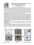
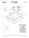
SPECIAL SERVICE TOOLS
37,. •
26
'-C'
32
34
.27
35
•
33 36 28
•
20
0
•
23
30
02 9
2
7
. .,
·�
-kL
•
·�:�
"'1' f:i
..
•
•
4
e
17
oco
11 8 11
1
0
J
3
18
25
i
6
19
21
24
�'��
- �- -�=- =- �� =--�-= �-=��-�·
40
39
••
��--..,
41
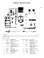
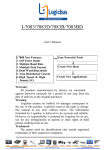
Figure 2
1021-2
The following is a detailed list of all special tools required to service the Spicer Model 30 Axle Housing
and Shaft Assembly_
Item No. Tool No.
1
2
3
4
5
6
7
*8
*9
*10
*11
*12
Description
Item No. Tool No.
D-113
D-263-1
Spreader
Adapter Blocks w/HoldDown Screws
DD-914-P Press
DD-914-9 Adapter Ring
C-293-39
Adapter Set - Differential
and Inner Pinion
Bearing Cones
SP-3289
Adapter Plug-Differential
Hub
D-128
Indicator Set
D-115
Scooter Gage
D-115-1
Pinion Height Block
D-138
Master Pinion Block
D-134
Master BearingDifferential
D-115-3
Arbor
*13
14
4
D-115-4
D-147
15
D-149
16
17
C-452
D-144
18
D-146
19
W-262
20
21
W-147-D
W-162
22
23
C-3281
C-3716-A
Description
Arbor Disc
Remover-Front Pinion
Bearing Cup
Remover-Rear Pinion
Bearing Cup
Remover-Yoke
Installer-Front Pinion
Bearing Cup
Installer-Rear Pinion
Bearing Cup
Installer-Rear Pinion
Bearing
Installer-Pinion Oil Seal
Installer-Yoke
Holder-Yoke
Installer-Differential
Side Bearings
Item No. Tool No.
24
25
**26
Description
Item No. Tool No.
D-131
C-4171
D-266
Slide Hammer
Handle-Universa!
Installer-Shaft BearingIn Tube
Installer-Shaft Seal**27
D-267
In tube
Installer-Shaft Bearing**28
D-268
In Housing
Installer-Shaft Seal**29
D-269
In Housing
*Pinion Setting Gauge and Master Differential
Bearing Kit No. D-115-30
**30
**31
**32
**33
**34
**35
**36
**37
**38
39
40
**Axle Shaft Bearing and Seal Removal and
Installation Kit No. D-30-AM
41
Description
D-270-1
Adapter Ring
L-4518-1
Receiver
L-4454-8
Thrust Bearing
L-4454-9
Main Body
L-4454-10 Screw
L-4454-11 Cup-Main Body
L-4454-12 "0" Ring
L-4454-13 Hex Nut (112-20)
L-4454-14 Washer
C-4053
Torque W rench300 Lbs.-Ft.
C-3952A
Torque Wrench150 Lbs.-Ft.
D-193
Torque Wrench50 Lbs.-Ft.
NOTE
Torque wrenches C-4053, C-3952A, and D-193 are optional and can be purchased separately. These
torque wrenches are not included in the axle tool kits.
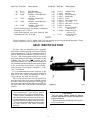
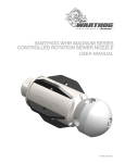
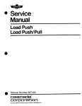
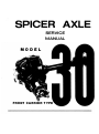
AX LE IDENTIFICATION
All Dana axles are identified with a complete
part number and the manufacturing date stamped
on the axle tube in IJs'' high (3.17mm) characters. A
typical identification number would be 610078-8,
12 107A and is interpreted as follows: the seven
digit dash number is the Dana part number for the
complete axle. The next three numbers are the
build date (month, day, year), the next number is
the assembly line that built the axle, the first letter
is the work shift, second letter is the manufac
turing facility. For example: December 1, 1980,
Line 7, First Shift.
It is recommended that when referring to the
axle, obtain the complete part number and build
date. To do this, it may be necessary to wipe or
scrape off dirt, etc. from the axle tube.
There is also an axle gear ratio tag location on
the right side of the cover plate and held in place
with two of the cover plate screws. This tag gives
the tooth combination of the ring gear and pinion,
the total gear ratio, and also the customer part
number.
Figure 3
NOTE
All maintenance and service require
removal of the cover plate and axle shafts.
Where vehicle installation restricts cover
plate removal,refer to vehicle manufacturer's
recommendations to remove the entire axle
housing and shaft assembly from the vehicle.
The procedures described here will consider
the axle housing and shaft assembly
removed.
1021-3
CAUTION
Do not apply vehicle weight to wheels
without half-shafts in place and fasteners
properly torqued.
Half-shaft to axle shaft flange bolt torque is
45 lbs.-ft. (6IN.m).
5
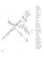
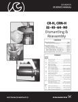
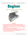
1-Axle Housing
2- Drive Gear Set
16
I
15
3-Oil Slinger (Inner)
4-Pinion Bearing (Inner)
5-Pinion Position Shims
6- Oil Baffel
�
1
RJJ�- 7
7-Pinion Bearing Preload
Shims
8-Pinion Bearing (Outer)
18
32
I
9- Oil slinger (Outer)
11-
10-0il Seal
3
13-Nut
ffr1 'l
�@I
14- Cover Gasket
15-Carrier Cover
34
0
16-Fill Plug
.,
(j)
'<
\ijY\§5�
�� �
-"li.%''4.1' -Ju
I \12
13
�.
\
End Yoke Assembly
12-Washer
4
25
�
/!{!�
r\ \:
17-Identification Tag
I
18- Cover Screw (10)
19- Differential Case
/
19
20-Drive Gear Screw (10)
1
2
21- Differential Bearing
Shims
�--
24
22-Differential Bearing
23- Differential Bearing Cap
7
1
·ro
35/ I
8
36
L--®
�
23
-
24- Differential Bearing
Cap Screw
·
25- Differential Cross Shaft
Lock Pin
26-Cross Shaft
27- Differential Pinion
Thrust Washer
28- Differential Pinion
9
29- Differential Side Gear
Thrust Washer
30- Differential Side Gear
31-Axle Shaft Snap Ring
32- Axle Shaft (L.H.)
33- Axle Shaft Seal (LH.)
34-Axle Shaft Bearing (LH.)
35-Axle Shaft Bearing (R.H.)
36-Axle Shaft Seal (R.H.)
37-Axle Shaft (R.H.)
Figure 4
1021-4
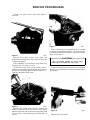
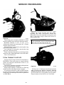
SERVICE PROCEDURES
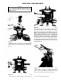
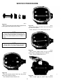
Loosen cover plate screws and allow lube to
drain out.
Figure 7
Figure 5
1021-7
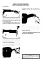
Slide it from the grove expanding it far enough
so that by rotating the shaft 180° , the snap ring can
be pulled off with a pair of pliers or pryed out with a
large screw driver.
1021-5
Remove cover plate screws, cover plate, and
gasket (discard old gasket). Tip carrier to allow lube
to drain completely.
CAUTION
Eye protection should be worn when
removing or installing the snap rings.
Place assembly on work bench and secure it by
clamping the axle tube in a vise.
At this time, clean the cover face of the carrier,
Inspect the snap ring to be certain it is not broken.
Retrieve any broken pieces from the housing before
proceeding.
making sure it is free from nicks and any particles
left by the old gasket. Remove RTV from two Vz''
diameter manufacturing holes.
Figure 6
1021-6
Remove axle shaft snap rings by rotating the
shaft so that the open side of the snap ring is
exposed, hold one side of the snap ring firmly with
a screw driver, while pushing on the other side, as
shown.
Figure 8
Remove the axle shafts.
7
1021-8
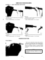
SERVICE PROCEDURES
SHAFT BEARINGS AND SEALS
DISASSEMBLY
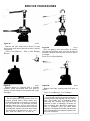
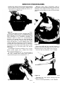
Using the procedure and tools described for
FIGURE 9, install the puller on the L.H. shaft
bearing.
Figure 9
1o21-9
Insert the puller through the axle shaft seal and
bearing and position it to a depth that will allow the
flange on the ends of the main body to expand into
the relief behind the needle bearing. Expand the
puller by holding the nut and turn the screw until
the puller centers itself.
Tools-L-4454-9 Mainbody, L-4454-10 Screw,
L-4454-11 Cup, L-4454-12 "0" Ring, L-4454-13 Hex
Nut (1/2-20) and L-4454-14 Washer. Figure 1 2
1021-12
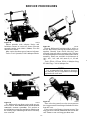
Place the receiver over the puller (adapter ring is
not required) and install the thrust bearing and
nut. Draw the bearing and seal from the housing.
Tools L-4518-1 Receiver,
Bearing, L-4454-13 Nut.
L-4454-8 Thrust
Discard seal and bearing and replace with
new one at time of assembly.
Figure 1 0
1021-10
Place adapter ring and receiver over the puller as
shown, install the nut on the screw and draw the
bearing and seal into the receiver by holding the
screw and turning the nut.
Tools-D-270-1 Adapter Ring, L-4518-1 Receiver,
L-4454-13 Nut, L-4454-14 Washer,
Discard seal and bearing and replace with
new one at time of assembly.
NOTE
Figure 1 1
It is recommended that whenever bearings
are removed, they are (regardless of mileage)
replaced with new ones.
1021-11
8
SERVICE PROCEDURES
ASSEMBLY - SH AFT BEARINGS AND SEALS
Figure 1 3
Figure 1 5
1o21-13
Assemble new L.H. shaft bearing. (Seat bearing
against shoulder.)
Tools-D-268 Installer, C-4171 Handle.
Figure 1 4
1021-15
Assemble new R.H. shaft bearing. (Tool controls
bearing installation depth.)
Tools-D-266 Installer, C-4171 Handle.
Figure 1 6
1021-14
Assemble new L.H. shaft seal. (Seat seal against
bearing.)
1021-16
Assemble new R.H. shaft seal. (Seat seal against
shoulder.)
Tools-D-269 Installer, C-4171 Handle.
Tools-D-267 Installer, C-4171 Handle.
CARRIER SECTION
DISASSEMBLY
With carrier positioned as shown and secured in
a vise, remove bearing caps. Note mating letters
stamped on caps and carrier. This is important at
time of assembly as they are to be assembled
exactly as removed. Letters or numbers should
correspond in both the horizontal and vertical
position.
NOTE
Axle shafts must be removed for service
procedures involving removal of the
differential.
Figure 1 7
1021-17
9
SERVICE PROCEDURES
Figure 1 8
1021-18
Mount spreader with adapter blocks and
holddown screws to carrier as shown. Do not
spread carrier over .020" (.50mm). Use dial
indicator as shown.
1021-2o
Figure 20
Remove differential bearings with a puller as
shown. Wire shims, bearing cup and bearing cone
together. Identify from which side they were
removed (ring gear side or opposite side.) If shims
are mutilated replace with new shims at the time of
assembly. Shims are available in thicknesses of
.003", .005", .010", and .030" (mm .08, .13, .25 and
.76).
Tools-DD-914-P Press, DD-914-9 Adapter Ring,
SP-3289 Plug, C-293-39 Adapter Set.
After carrier has been spread, remove indicator.
Tools-D-113 Spreader, D-263-1 Adapter Blocks.
NOTE
.
Figure 1 9
..
It is recommended that whenever bearings
are removed, they are (regardless of mileage)
replaced with new ones.
•
Figure 21
1o21-19
1021-21
Place a few shop towels over the vise to prevent
the ring gear teeth from being nicked after it is free
from the case.
Pry differential case from carrier with two pry
bars as shown. After differential case has been
removed, remove s preader. Use caution to
avoid damage to ring gear and pinion. Mark or tag
the bearing cups indicating from which side they
were removed.
Place case in vise. Remove ring gear screws. Tap
ring gear with rawhide hammer to free it from the
case. Remove case and ring gear from vise.
10
SERVICE PROCEDURES
NOTE
It is recommended that whenever the ring
gear screws are removed, they are replaced
with new ones.
. ;.� �L
1
?
-··
Figure 22
1o21-24
Figure 24
To remove side gears and pinion mate gears,
rotate the side gears. This will allow the pinion
mate gears to turn to the opening of the case.
Remove pinion mate gears and also the spherical
washers behind the gears. Lift out gears and
thrust washers. Inspect all parts, including the
machined surfaces of the case itself. Where
necessary replace all worn parts. If excessive wear
is visible on all parts, it is suggested that the
complete differential assembly be replaced. If any
one of the gears are to be replaced, they are to be
replaced as a set.
1021-22
Replace case in vise and drive out lock pin which
secures the pinion rnate shaft. Use a small drift as
shown.
Figure 25
1021-2s
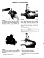
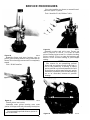
Turn nose of carrier in a vertical position to
remove pinion nut. Hold end yoke with tool as
shown, and remove pinion nut and washer.
Figure 2 3
1o21-23
Remove pinion mate shaft with drift as shown.
Tool-C-3281 Holding Wrench.
11
SERVICE PROCEDURES
Figure 26
1021-26
Remove end yoke with tools as shown. If yoke
shows wear in the area of the seal contact, it should
be replaced.
Figure 28
Pull out pmwn seal with puller as shown.
Discard seal. Replace with new seal at time of
assembly. Remove bearing cone and outer pinion
oil slinger.
Tools-D-131 Slide Hammer.
Tools-C-452 Remover - Yoke, C-3281 Holding
Wrench.
I _J
Figure 27
1021-2s
1021-27
Figure 29
Remove pinion by tapping with a rawhide
hammer. Catch the pinion with your hand to
prevent it from falling to the ground and being
damaged.
1021-29
Remove the inner bearing cup with tools as
shown.
Tools-D-149 Remover, C-4171 Handle.
NOTE
An oil baffle and pinion position shims are
located between the bearing cup and carrier
bore. The baffle will be damaged when
removing the bearing cup and must be
replaced at time of assembly. If shims are
bent or nicked, they should be replaced at
time of assembly. Wire the shim stack
together (including the baffle) and measure
each. If stack has to be replaced, replace with
the same thickness.
NOTE
On the spline end of the pinion, there are
bearing preload shims. These shims may
stick to the bearing or the pinion or even fall
out. The shims are to be collected and kept
together since they will be used later in
assembly. Try not to mutilate shims. If shims
are mutilated, replace with new ones. Shims
are available in thicknesses of .003", .005",
.010", and .030" (mm.S, .13, .25 and .76).
12
SERVICE PROCEDURES
NOTE
The oil slinger located between the bearing
cone and the pinion head affects pinion
position and must be kept intact for
assembly.
ASSEMBLY - CARRIER SECTION
Figure 30
1021-30
Turn nose of carrier down. Remove outer pinion
bearing cup as shown. Locate driver on back edge
of cup, drive cup out of carrier. CAUTION: Do not
nick carrier bore.
Figure 32
1021-32
Place differential case in vise as shown. Apply
grease to new side gear thrust washers and hubs of
side gear. Assemble both side gears. Apply grease
to new pinion mate spherical washers and the
pinion mate gears. Assemble pinion mate gears.
An easy way to assemble the side gears and pinion
mate gears is to have all parts lubricated before
assembly. Assemble both side gears and thrust
washers, hold them in place with hand, then
assemble the pinion gears to hold the side gears in
place.
Tools-D-147 Remover, C-4171 Handle.
Rotate the side gears until the holes of the
washers and pinion gears line up with the holes of
the case. If the gears cannot be rotated by hand,
install one of the axle shafts into the side gear
spline and use a pipe wrench to turn the shaft.
Figure 31
1021-31
Remove mner pmwn bearing with tools as
shown.
Figure 33
Tools-DD-914-P Press, DD-914-9 Adapter Ring,
C-293-39 Adapter Set.
1021-33
Install pinion mate shaft. Assemble lock pm.
Peen metal of case over pin to lock in place.
13
SERVICE PROCEDURES
Figure 34
Figure 36
1021-36
Assemble differential case into carrier (less
pinion). Mount dial indicator, with a magnetic
base as shown. Locate tip of indicator on flat
surface of one of the gear screws. Mark screw with
a piece of chalk. Force the differential assembly as
far as possible in the direction towards the
indicator. With force still applied, set indicator at
zero. (0).
1021-34
Be sure flange face of the case is free of nicks or
burrs. Assemble ring gear to case using new ring
gear screws. Draw up screws alternately and
evenly.
Torque screws to 45-60 lbs. ft. (61.0-81.3 N.m).
Tool-Indicator D-128.
NOTE
Indicator should have a minimum of .200"
(5.08mm) travel.
Figure 37
1o21-3s
Figure 35
Remove all nicks, burrs, dirt, etc. from differential
case bearing hubs to allow master bearings to
rotate freely.
Install master differential bearing onto case.
Tools-Master Bearings D-134.
14
1021-37
Force the differential assembly as far as it will
go in the opposite direction. Repeat these steps
until the same reading is obtained.
Record the reading of the indicator.
This will be the total amount of shims required
(less preload) and will be calculated later during
assembly.
SERVICE PROCEDURES
After making sure the readings are correct,
remove indicator and differential assembly from
housing. Do not remove master bearings from
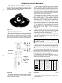
On the button end of each pinion there is etched
a plus (+) number, a minus (-) number, or a zero (0),
which indicates the best running position for each
particular gear set. This dimension is controlled by
the shim pack which includes the baffle behind the
inner bearing cup, and the oil slinger between the
bearing cone and the pinion head.
differential case at this time.
For example: if a pinion is etched +3 (m + 8), this
pinion would require the .003" (.08mm) less shims
than a pinion etched "0". This means by removing
shims, the mounting distance of the pinion is
increased to 2.253" (57.2mm), which is just what a
+3 (m + 8) indicates. Or if a pinion is etched -3 (m-8),
we would want to add .003" (.08mm) more shims
than would be required if the pinion were etched
"0". By adding .003" (.08mm) shims the mounting
distance of the pinion was decreased to 2.24 7" (57
.lmm) which is just what a -3 (m - 8) etching
indicated.
Figure 38
If the old ring and pinion set is to be reused,
measure the old shim pack and build a new shim
pack to this same dimension. The baffle is
considered as part of the shim pack.
1021-38
View of ring and pinion set.
Ring gears and pinions are supplied in matched
sets only. Matching numbers on both the pinion
and ring gear are etched for verification. If a new
gear set is being used, verify the numbers of each
pinion and ring before proceeding with assembly.
in.
Pinion
Preload 1 .003
Shims .005
.o1o
L .030
U6 l
in.
mm.
j
Pinion Oil Baffle
�
Pinion Position
,- Shims
��--+---E�
{
To change the pinion adjustment, shims are
available in thicknesses of .003", .005", and .010"
(mm .08, .13 and .25).
NOTE
If baffle or slinger is bent or mutilated, it
should be replaced.
mm.
( .08 l
( .13 J
Measure the baffle, the slinger and each shim
separately with a micrometer and add together to
get total shim pack thickness from original build
up.
( .251
If a new gear set is being used, notice the (+) or (-)
etching on both the old and new pinion and adjust
the thickness of the new shim pack to compensate
for the difference of these two figures.
.003 ( .08 J
.005 (.13J
.010 ( .251
Pinion Oil Slinger
For example: If the old pinion reads +2 (m + 5)
and the new pinion is -2 (m - 5), add .004" (.lOmm)
shims to the original shim pack.
Front and Rear
Model 30
2.250 in. ( 57.15) mm.
Mtwi'IIIMMwti..
OI.:I'IRIIft
M11k1•1
Centerline of
+•
Ring Gear
-I
-I
-1
+1
+I
+1
+0000
+0001
+0006
+01XO
+000<
+000!
+0002
+0001
+0001
+I
+0001
+0006
+01XO
+000<
+000!
+0002
+1
+0006
+01XO
+000<
+000!
+0002
+0001
+I
+01XO
+000<
+000!
+0002
+0001
+000<
+0001
+0002
+0001
+000!
to002
+0001
+0002
+0001
-I
+0001
-0001
Figure 39
Figure 40
1021-39
The distance from the centerline of the ring gear
to the button end of the pinion for the Model 30 axle
is 2.250 inches (63.5 mm).
-000\
+•
-0001
-0001
-0002
0001
-0002
000!
-0001
-0001
-000!
000<
-000\
-0001
-000!
-000<
01XO
-0001
-OOOJ
-000<
-0001
-0006
-000!
-000<
-0001
-0006
-0001
-0000
-01XO
0006
-0008
1021-40
Use pinion setting chart shown as a guide to set
pinion position.
15
SERVICE PROCEDURES
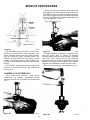
Figure 41
1021-41
Figui'e 43
View of cross arbor and arbor discs, height block,
scooter gage, and master pinion block.
1021-43
Place arbor discs and arbor into cross bores of
the carrier as shown.
Tools-Arbor D-115-3, Arbor Discs D-115-4.
NOTE
Cross arbor and master bearing discs can
be used on both the Model 30 and Model 44
axles. Use small diameter discs for Model 30
axles.
NOTE
Be sure that all carrier bores are free from
all nicks, dirt or any other contamination.
Figure 44
1021-44
Place pinion height block on top of master
pinion block, and against arbor as shown.
Tools-Pinion Height Block 115-1.
Figure 42
1o21-42
Place the master pinion block into the pinion
bore of the carrier as shown.
Figure 45
Tool-Master Pinion Block D-138.
1021-45
Place scooter gage on small step of pinion
16
SERVICE PROCEDURES
height block. Apply pressure with fingers making
sure the gage is flat on the pinion height block,
while pressure is applied, set indicator at zero "0".
Tool-Scooter Gage D-115.
Measure each shim separately with a
micrometer and add together to get total shim pack
thickness. The baffle and the slinger are to be
measured and included as a part of the total shim
pack.
1o21-4s
Figure 46
Slide scooter gage over arbor. As gage slides over
top of arbor, it will travel in a clockwise direction.
When indicator is on center of arbor (on top) it will
stop travelling in a clockwise direction. If
indicator starts to travel in a counterclockwise
direction, this means that you have passed the
center (top) of the arbor. Record only the reading
when the indicator is at the highest point. This
reading indicates the amount of shims necessary
to obtain the correct shim pack, plus (+) or minus (-)
the etching on the button end of the pinion. If the
etching is zero (0) the shim pack will remain
unchanged.
Figure 48
1021-48
Place the baffle and the required amount of
shims in the inner bearing bore, drive the inner
bearing cup into carrier with tools as shown.
For example: If a pinion is etched +3 (m + 8), this
pinion would require .003" (.08mm) less shims
than a pinion etched zero "0".
Tools-D-146 Cup Installer, C-4171 Handle.
If a pinion is etched-3 (m - 8), we would want to
add .003" (.08mm) more shims than would be
required if the pinion were etched zero "0".
Figure 49
1021-49
Assemble the outer pinion bearing cup into
carrier as shown.
Figure 47
Tools-D-144 Cup Installer, C-4171 Handle.
1021-47
17
SERVICE PROCEDURES
Use yoke installer (as shown) to assemble end
yoke onto spline of pinion.
Tool-Installer W-162, Holder C-3281.
Figure 50
1021-50
Assemble slinger and inner bearing cone on
pinion, place bearing installer over pinion stem as
shown. Drive bearing on stem until it is completely
seated.
Tool-W-262 Installer.
Figure 51
Figure 52
1021-52
Assemble washer and pmwn nut. Torque nut
until it requires 10 lbs.-in. (1.13 N.m) to rotate
pinion. Rotate pinion several t;,,�s before checking
pinion position. This is to seat the bearings and
assure a more accurate reading of pinion depth
setting.
NOTE
The reason for not assembling preload
shims and new pinion oil seal at this time, is
due to the possibility of having to adjust
pinion preload or pinion adjustment. It would
be necessary to again remove the seal, and as
mentioned, whenever seals are removed they
are to be discarded, because of possible
damage.
1021-51
Install pinion into carrier.
Assemble outer pinion bearing cone, outer
pinion oil slinger, and end yoke onto pinion spline.
NOTE
Do not assemble preload shims or pinion oil
seal at this time.
Figure 53
18
1021-53
SERVICE PROCEDURES
Place arbor and arbor discs (small diameter
discs for Model 30 axle) into cross bore of carrier.
Place pinion height block on button end of pinion.
Set dial indicator on zero "0". (Refer to FIGURE
45).
Slide scooter gage across or over arbor.
If pinion preload is within specifications, remove
pinion nut, washer, end yoke and pinion. Assemble
new pinion oil seal into housing as shown. Apply
a light coat of oil to the lip of oil seal.
Tools-W-147D Seal Installer, C-4171 Handle.
Indicator will read a plus (+) or minus (-) at its
highest point, depending on the etching of the
p1mon.
NOTE
Indicator reading within .002 (.05mm) of
etching is considered acceptable.
If pinion position is found to be within
specifications, continue with build up. If
pinion position is not within specifications,
change shim pack thickness under inner
bearing cup.
Insert pinion into carrier.
Assemble preload shims (which were removed
during disassembly) onto the pinion.
Assemble bearing cone, slinger, end yoke, washer
and pinion nut.
Torque pinion nut to 200-220 lbs. ft. (271-298
N.m).
Tool: Holder C-3281, Torque Wrench C-4053.
Using an inch pound torque wrench rotating
torque of pinion should read between 20-40 lbs. inch
(2.3-4.5 N •m) with new bearings. If original
bearings are used, torque reading should be 10-20
lbs. in. (1.13-2.26 N.m). To increase preload, remove
shims, to decrease preload, add shims.
Figure 55
1021-55
Install pinion. Assemble end yoke, washer, and
new pinion nut. Torque nut to 200-220 lbs. ft. (271298 N•m).
Tools-C-3281 Yoke Holder.
Figure 56
1021-56
Using an inch lb. torque wrench as shown, rotate
pinion. Torque of pinion should read between 20-40
lbs. in. (2.3 - 4.5 N.m).
Figure 54
To increase preload, remove shims; to decrease
preload, add shims.
1021-54
19
SERVICE PROCEDURES
Set up dial indicator as shown. Be sure to locate
dial indicator on same ring gear screw as shown in
FIGURE 36. Force ring gear to mesh with pinion
gear. Rock ring gear to allow the teeth of the gears
to mesh. With force still applied to the differential
case, set indicator at zero "0".
Tool-Indicator D-128.
Dlffll!!HTIAL lURING SIIIM PA()(S
Figure 57
1021-57
The illustration shows the arrow in the pinion
pointing in two directions_ The direction of the
arrow pointing towards the end yoke indicates
that by removing pinion locating shims, the
distance from the centerline of the axle to pinion
button, is increased giving a plus reading. The
preload shim pack does not affect the pinion depth
setting.
Arrows on the ring gear illustrate the method to
increase or decrease backlash, and differential
bearing load_
Figure 59
1021-59
Force the differential assembly (ring gear) away
from the pinion gear, to obtain an indicator
reading. Repeat until the same reading is obtained
each time. This reading will be the necessary
amount of shims between the differential case and
differential bearing on the ring gear side. Remove
indicator and differential case from the carrier.
Remove master bearings from differential case_
ASSEMBLY OF DIFFERE NTIAL
Place differential assembly (with pinion
assembled) into housing_ Differential master
bearings should still be installed to differential
case.
Figure 58
1021-58
20
Figure 60
1021-60
SERVICE PROCEDURES
Assemble the required amount of shims onto
hub (ring gear side) as determined in FIGURE 59.
Place bearing cone on hub of case. Use bearing
installer to seat bearing cone as shown. Step plate
is used to prevent possible damage to hubs, while
assembling bearings.
Tools-Installer C3716-A, Handle C-4171.
Assemble the remaining of the total shim pack
which was determined in FIGURE 37 on the
opposite side of the differential case. Add an
additional .010" (.25mm) of shims on this side to
provide differential bearing preload. Assemble
differential bearing using the tools shown.
For example:
In FIGURE 37 (less pinion) a total of .085"
(2.03mm) indicator reading was recorded.
In FIGURE 59 (with pinion) a total of .055"
(1.4mm) indicator reading was recorded. This
leaves a balance of .030" (.76mm) of shims for the
opposite side and adds up to the .085" (2.16mm)
which was first recorded.
Add an additional .010" (.25mm) shims on the
opposite side for bearing preload and backlash.
Figure 62
A ssemble differential
differential bearing cones.
1021-62
bearing cups to
Install differential assembly onto carrier.
Use a rawhide hammer to seat differential
assembly into cross bore of carrier. Care should be
taken to avoid nicking the teeth of the ring gear
and pinion during assembly. Remove spreader.
Ring Gear Side .055" (1.4mm).
Opposite Side .030" (.76mm) balance plus
opposite side preload .010" (.25mm) for a total of
.040" (1.02mm).
Figure 63
1o21-6l
Install bearing caps. Make sure the letters
stamped on the caps correspond with those on the
carrier. Torque bearing cap screws to 35-50 lbs. ft.
(47.5 - 67.8 N.m).
Figure 61
1021-s1
Mount spreader with adapter blocks and holddown screws and indicator to carrier as shown.
Do not spread carrier ove r .020" (.50 mm).
After carrier has been spread, remove indicator.
Tools-D-113 Spreader, D-263-1 Adapter Blocks.
21
SERVICE PROCEDURES
Figure 65
1o21-6s
Install axle shafts through side gear spline,
exposing the snap ring groove inside the
differential. Place the snap ring in the groove and
force it into place using a blunt screw driver or
other suitable tool.
Figure 64
1021-64
Check ring gear and pinion backlash in three
equally spaced points with dial indicator shown.
Backlash tolerance is .005" to .009" (.13 to
.20mm) and cannot vary more than .003" (.75mm)
between points checked.
CAUTION
To avoid injury, wear eye protection. Ifthe
tool slips, the snap ring may fly out.
High backlash is corrected by moving the ring
gear closer to the pinion.
Low backlash is corrected by moving the ring
gear away from the pinion.
These corrections are made by switching shims
from one side of the differential case to the other.
Tool-D-128 Indicator.
TOTAL TORQUE TO ROTATE
Use an inch lb. torque wrench as illustrated in
FIGURE 56. The total torque to rotate both the
pinion and ring gear should read 40 lbs.-in. (4.5
N •m) maximum.
Low torque reading is corrected by adding shims
to the side opposite the ring gear.
High torque reading is corrected by removing
shims from the side opposite the ring gear.
If it becomes necessary to add or subtract shims
for total turning torque, check backlash again to
make sure it is within specifications as spelled out
in FIGURE 64.
22
Figure 66
1021-66
Fill the two W' diameter manufacturing holes
with silicone-type sealant material meeting
ASTM3 specification GE303, A19, B37, E16, Z1, Z2
and Z3. Install new cover gasket and cover plate.
Torque screws to 30-40 lbs.-ft. (40.7-54.2 N•m).
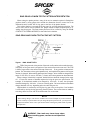
SPICER®
RING GEAR & PINION TOOTH PATTERN INTERPRETATION
When setting the pinion position, many of the service manuals required a final pinion
position check by using gauges that verified the dimension from the center line of the
differential carrier (center line of ring gear) to the face of the pinion (button).
This surface (button) is not used on all new gears for verifying the pinion position. The
service tools will be used to establish the proper amount of shims required prior to in
stalling the pinion gear. The final pinion position will be verified by using the GEAR
CONTACT PATTERN METHOD, as described in this bulletin.
RING GEAR AND PINION TOOTH CONTACT PATTERN
HEEL
\o--..l.-
Figure
1
LENGTHWISE
BEARING
ARC
_____
j
__ _
- RING GEAR TOOTH
The TOE of the gear tooth is the portion of the tooth surface at the end towards the center.
The HEEL of the gear tooth is the portion of the tooth surface at the outer end. The TOP
LAND of a gear tooth is the surface of the top of the tooth.
Every gear has a characteristic
pattern. The illustrations show typical patterns only, and explains how patterns shift as gear
location is changed. When making pinion position changes, shims should be changed in the
range of .002 inch (.05 mm) to .004 inch (.10 mm) until correct pattern has been obtained.
When a change in backlash is required, backlash shims should be changed in the range
of 1-112 times the amount of backlash required to bring the gears into specification. For
example, if the backlash needed to be changed by .004 inch (.10 mm), the shim pack
should be changed by .006 inch ( . 15 mm) as a starting point. The actual amount of backlash
change obtained will vary depending upon the ratio and gear size.
High backlash is corrected by moving the ring gear closer to the pinion. Low backlash
is corrected by moving the ring gear away from the pinion. These corrections are made by
switching shims from one side of the differential case to the other.
NOTE
When making changes, note that two variables are involved. Example: If you have the back
lash set correctly to specifications and you change the pinion position shim, you may have to
readjust the backlash to the correct specification before checking the pattern. Refer to pattern
interpretation.
WARNING: Gear teeth may have sharp edges.
When handling gears, use care to avoid personal
injury.
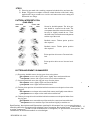
STEPS
(I) Paint ring gear teeth with a marking compound to both the drive and coast side.
(2) Rotate ring gear one complete revolution in both directions while load is being
applied with a large screwdriver or similar tool between the carrier casting and
differential case flange.
PATTERN INTERPRETATION
(RING GEAR)
DRIVE SIDE
HEEL
TOE
COAST SIDE
TOE
HEEL
��
Normal or desirable pattern. The drive pat
tern should be centered on the tooth. The
coast pattern should be centered on the tooth,
but may be slightly toward the toe. There
should be some clearance between the pattern
and the top of the tooth.
Backlash correct. Thinner pinion position
shim required.
Backlash correct. Thicker pinion position
shim required.
Pinion position shim correct. Decrease back
lash.
Pinion position shim correct. Increase back
lash.
PATTERN MOVEMENTS SUMMARIZED
(I) Decreasing backlash moves the ring gear closer to the pinion.
Drive pattern (convex side of gear) moves slightly lower and toward the toe.
Coast pattern (concave side of gear) moves lower and toward the toe.
(2) Increasing backlash moves the ring gear away from the pinion.
Drive pattern moves slightly higher and toward the heel.
Coast pattern moves higher and towards the heel.
(3) Thicker pinion position shim with the backlash constant moves the pinion closer to the
nng gear.
Drive pattern moves deeper on the tooth (flank contact) and slightly toward the toe.
Coast pattern moves deeper on the tooth and toward the heel.
(4) Thinner pinion position shim with the backlash constant moves the pinion further from
the ring gear.
Drive pattern moves toward the top of the tooth (face contact) and toward the heel.
Coast pattern moves toward the top of the tooth and slightly toward the toe.
Specifications, descriptions and illustrations contained in this manual are as accurate as known aJ
time this publication was approved for printing. Dana Corporation, Spicer Axle Division, reserves then<
to make changes from time to time without notice or obligation, in specifications, descriptions, ana
illustrations; to discontinue models or revise designs.
BULLETIN NO. 5325