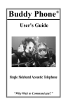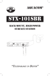
1
STX-101, STX-101M,
& STX-101SB
P ORTABLE S URFACE S TATION
“TECHNOLOGY IN DEPTH”
- IMPORTANT SAFETY NOTICE (Please read before using product)
It is absolutely essential that all divers are properly trained and
equipped and fully understand this owner's manual before attempting to use the STX-101/M/SB or any other underwater product.
While the STX-101/M/SB provides divers with good underwater
communications, it does not change or eliminate the potential
hazards of diving!
- NOTE This manual and the information contained herein are provided
for use as a maintenance and operation guide. No license or rights
to manufacture, reproduce, and/or sell either the manual or articles described herein are given. Ocean Technology Systems reserves the right to change specifications without notice.
©1999–2005 Ocean Technology Systems
506063-000 Rev. D
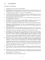
Table of Contents
Section 1: Introduction ...................................................................... 1
1.1 Features .................................................................................... 1
1.2 Specifications ............................................................................ 3
1.3 Functions ................................................................................... 4
Section 2: Batteries and Installation .................................................. 6
2.1 Battery Selection ...................................................................... 6
2.2 Battery Installation .................................................................... 6
2.3 Low-Battery Alert .................................................................... 8
2.4 RB-6V 6-Volt Rechargeable Battery ....................................... 8
2.5 Battery Chargers ...................................................................... 8
2.6 Alternate Power Source ........................................................... 9
Section 3: Operation ........................................................................ 10
Section 4: Maintenance ................................................................... 12
Section 5: Helpful Hints and Tips .................................................... 13
5.1 Transducer .............................................................................. 13
5.2 Hand-Held Microphone or Headset ....................................... 13
5.3 Placement of the STX-101/M/SB .......................................... 13
5.4 Talking and Listening .............................................................. 13
5.5 In the Beginning ...................................................................... 14
Section 6: Troubleshooting .............................................................. 15
Limited Warranty ............................................................................ 17
i
SECTION 1
INTRODUCTION
Congratulations! You have just purchased the finest, state-of-the-art underwater communication system available. The Aquacom® STX-101, STX101M, and STX-101SB are compact, ultrasonic, single sideband transceivers designed to allow surface-to-diver and/or diver-to-surface through-water communications. The STX series employs digital signal processing
techniques, which ensure the highest performance possible.
The STX-101/M/SB offers many useful features to ensure user-friendly
performance, such as front-panel squelch control, a heavy-duty panel
speaker, a record-out connector (female RCA), a multichannel selector
(STX-101 and STX-101M only), a heavy-duty waterproof housing, external
power accommodations for 12 volts, a headset (optional) with boom microphone output, easy battery access, and much more. In all, the STX-101/M/
SB Portable Surface Station is second to none!
1.1
FEATURES
The Aquacom® STX-101, STX-101M, and STX-101SB are packaged in
the same housing (although the STX101SB's panel controls differ somewhat from those of the other two) and are similar transceivers. The major
differences among the three products are as follows (also see Table 1):
The STX-101 is equipped with four channels, including Channel 1 (32.768
kHz upper sideband), which is commonly used by sport divers. Most of the
Buddy Phone® systems utilize Channel 1. If an STX-101 user makes a
selection other than Channel 1, 2, 3, or 4, the transceiver will emit a beeping
sound to alert the user that the selected channel is not available. The unit is
rated at 10 watts and comes standard with a 32.768 kHz transducer assembly and a hand-held microphone. Optional rechargeable batteries and a
charger are available, although alkaline batteries can be used. The STX101 is designed to operate primarily with the SSB-2010 commercial transceiver but also works great with our standard Buddy Phone® transceivers
(such as the XT-100, MKII-BUD, MTS-BUD, SCU-BUD, RX-100, etc.),
the SSB-2001B-2, the SP-100, and the Magnacom® MAG-1001S, MAG1003D, MAG-1004HS, and MAG-1003-PS—as well as any other single
sideband transceiver within range and on the same frequency.
1
The STX-101M is equipped with eight channels, including the most commonly used military frequency, 25 kHz upper sideband. The first four channels are the same as those of the STX-101. Provided with the transceiver
are rechargeable batteries and the RC-13i multi-voltage (90V to 234V)
battery charger, although alkaline batteries can be used. The STX-101M is
rated at 15 watts and is equipped with a heavy-duty 25 kHz transducer
assembly. The hand-held microphone is a high-quality Shure, ensuring clear
communications. The STX-101M was designed to meet the demands of the
military diver and functions with our SSB-1001B U.S. Navy-approved diver
transceiver. The STX will operate with most transceivers on the market, as
well as virtually all of the OTS wireless transceivers produced.
The STX-101SB is equipped with one channel, either 25kHz upper sideband (standard) or 8kHz upper sideband (optional). It is a high-power (50watt) surface station designed to be used for communication with diving
bells that use the BELL-200 bell back-up system. Rechargeable batteries
and the RC-13i multi-voltage (90V to 234V) battery charger are provided
with the transceiver (alkaline batteries should not be used with the STX101SB). The system includes a high-quality Shure hand-held microphone.
Note: This manual will refer to the STX-101, STX-101M, and STX101SB transceivers collectively as STX-101/M/SB. Wherever we present
information that is not common to all, we will refer to them by their
individual model numbers.
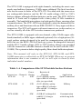
Table 1: A Comparison of the STX Portable Surface Stations
Power
Transceiver Channels Rating
STX-101
4
10W
Batteries &
Charging
(2) 6V, alkaline, springtype or RB-6V rechargeable (not provided)
Application
Sport/Commercial
STX-101M
8
15W
(2) 6V, alkaline, springtype or RB-6V rechargeable with RC-13i charger
(provided)
Military
STX-101SB
1
50W
(2) RB-6V rechargeable
with RC-13i charger
(provided)
Communication
with diving bells
2
1.2
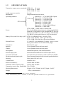
SPECIFICATIONS
Transmitter output power (nominal): STX-101: 10 watts
STX-101M: 15 watts
STX-101SB: 50 watts
Audio output to speaker:
4 watts
Modulation:
Single sideband with no carrier
Operating channels:
{
{
STX-101
STX-101M
Power:
Channel #1:
Channel #2:
Channel #3:
Channel #4:
Channel #5:
Channel #6:
Channel #7:
Channel #8:
32.768 kHz USB1 (Sport)
32.768 kHz LSB1
31.250 kHz USB
31.250 kHz LSB
28.5 kHz USB
28.5 kHz LSB
25 kHz USB (Military)
25 kHz LSB
STX-101SB: 25kHz USB1 or 8kHz USB
Two 6-volt alkaline lantern batteries with springs (MN908
Duracell or equivalent) or two optional RB-6V gel-cell
batteries and an RC-13 or RC-13i charger. STX-101SB:
Use RB-6V rechargeable batteries only (not alkaline).
Battery Life (with 10% duty cycle)2: STX-101: Alkaline 20 hrs., gel cells 12 hrs.
STX-101M: Alkaline 12 hrs., gel cells 8 hrs.
STX-101SB: Gel cells 6 hrs. (do not use alkaline)
External Power:
12 volts DC at a minimum of 4 amps. Access via the
front panel with the use of mini banana plugs.
Transducer:
Piezoelectric type
Squelch:
User adjustable from the front panel
Volume:
User adjustable from the front panel
Microphone:
Hand-held, dynamic, 200-ohm impedance
Record output jack:
Panel-mounted female RCA connector (line level)
Activation (On/Off):
On connection of transducer cable to STX-101/M/SB
Headset/external speaker jack:
Panel-mounted banana jacks (external speaker/headset)
Housing:
Heavy-duty UK 603 case
Control Panel:
Stainless steel
Receiver sensitivity:
Greater than 100 dBv
Automatic Gain Control (AGC):
Greater than 100 dBv
Transmitter speech freq. bandwidth: 300–3500 Hz
Housing Dimensions:
Height: 6.500", Width: 14.000", Depth: 10.600"
Weight:
12 lbs. (with batteries)
1. USB is "upper sideband"; LSB is "lower sideband."
2. The actual battery life is variable, so the time periods stated here are approximate.
3
1.3
FUNCTIONS
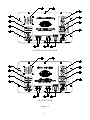
See Figure 1 throughout.
1.
2.
3.
4.
5.
6.
7.
8.
9.
10.
11.
12.
13.
HANDLE: One of two front-panel handles.
SPEAKER switch: Toggle switch used to turn the front-panel speaker on or off.
RECORD OUT: This female RCA receptacle is used to connect to any type of
recording system. It supplies “Line Level” signal output.
12 VOLTS POWER/CHG: Used when an external 12-volt DC power source is
desired. Ensure the source has a minimum of 4 amps. This receptacle is also
used to charge rechargeable batteries.
MICROPHONE: This receptacle is used for a hand-held microphone or headset with boom microphone.
HEADSET: Can be used with an optional THB-101 headset. You can also use
this outlet for an external, remote speaker using a dual banana plug.
BATTERY-CHARGING RELIEF VALVE: This relief valve must be open when
charging rechargeable batteries. We also recommend that the relief valve be
opened when transporting the unit via aircraft, to allow depressurization at
increased altitude.
XDUCER ON/OFF: The unit will power up and cycle to the receive mode when
the transducer cable is connected to the female receptacle (#8). If you are not
using the system, disconnect the transducer cable to conserve energy.
CHANNEL: The STX-101M has eight channels, the STX-101 has four channels, and the STX-101SB has one channel (Section 1.2, Specifications). If using
the STX-101 and you choose an unprogrammed channel, a beeping sound will
alert you to select a working channel. The STX-101SB's channel select switch
is labeled with channels A and B, but both settings access the same channel.
SQUELCH: The squelch control is designed to help suppress background
noise created by sea creatures and/or man-made sound (e.g., snapping shrimp,
croakers, or motor boat or pool pump noise). When the squelch is rotated
completely counterclockwise, the squelch is deactivated and all noises within
range will be heard. You will also obtain the maximum reception range. When
you rotate the squelch clockwise, you begin to eliminate background noise.
However, you also decrease your range.
VOLUME: The volume control adjusts the listening volume from the frontpanel speaker. Clockwise increases volume, and counterclockwise decreases
it.
SCREW: One of ten (10) Phillips-head, #8-32 stainless steel screws. They all
must be removed to gain access to the battery compartment and mother board.
Be careful not to lose the screws.
SPEAKER: Heavy-duty front-panel speaker.
4
(A) STX-101 & STX-101M
(B) STX-101SB
Figure 1
5
SECTION 2
BATTERIES AND INSTALLATION
The STX-101/M is powered by two 6-volt, heavy-duty, alkaline spring-type
batteries (MN908 Duracell) or two RB-6V rechargeable 6-volt batteries.
With the STX-101SB, use only lead-acid rechargeable batteries, not alkaline.
2.1
BATTERY SELECTION
With the STX-101/M, for best results use two 6-volt, heavy-duty, alkaline
spring-type lantern batteries: Eveready Heavy Duty Alkaline #528 or
Duracell Heavy Duty Alkaline #ID9150 will provide the best results for
most diving operations. You can use standard 6-volt, spring-type lantern
batteries in a pinch; however, battery life will be greatly reduced. IMPORTANT NOTE: You must use 6-volt lantern batteries with spring contacts. The threaded type of lantern batteries will not work. The RB-6V
rechargeable batteries should be used with the STX-101SB; do not use
alkaline batteries.
2.2
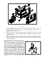
1.
2.
3.
4.
5.
6.
7.
BATTERY INSTALLATION
Locate and remove the ten screws found on the front panel (Figure 1,
#12). You do not have to remove the front-panel screws located around
the front-panel speaker grill (Figure 1, #13).
Carefully remove the front panel. Be careful not to stress the connecting wire harness while setting the front panel aside.
Remove the wing nuts (Figure 2, #14) and set aside.
Remove the battery retaining bracket (Figure 2, #16) and set aside.
Insert two lantern batteries, battery springs facing toward the battery
PC board (Figure 2, #15). Ensure they are firmly seated in the bottom
of the battery bracket housing.
Replace the battery-retaining bracket and tighten the wing nuts securely.
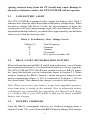
Ensure the wire harness is plugged into the correct connector on the
PC board (Figure 3). When alkaline batteries are used, the harness
(Figure 3, #19) must be plugged into receptacle J10 (Figure 3, #21).
When rechargeable batteries are used, the harness must be plugged
into J5 (Figure 3, #22). If this procedure is not followed properly,
damage may occur. If you are trying to charge batteries with the
6
Figure 2
8.
9.
harness plugged into the wrong socket, the charger's current will not
be channeled to the batteries. It is also important you do not try to
charge alkaline batteries.
While the unit is open, you may want to verify that the four screws
securing the feet and the battery plate assembly are tightly secured
(Figure 2, #20).
Replace the front panel, ensuring you have not pinched any wires. Do
not overtighten the ten front-panel screws (technical information: tighten
to 6 inch-pounds).
Important Note: The silver pads located on the battery PC board (Figure 2, item #15) are configured to accept the spring contacts found on a
6-volt, spring-type lantern battery at
any axis at which the 6-volt lantern
batteries are installed. The spring
contacts of the batteries must be in
contact with the PC board in order
for the system to work. Installing the
batteries in the wrong direction
7
Figure 3
(spring contacts away from the PC board) may cause damage to
the unit or batteries, and/or the STX-101/M/SB will not operate.
2.3
LOW-BATTERY ALERT
The STX-101/M/SB is equipped with a unique low-battery alert. Table 2
indicates how often the alert tone sounds as the battery voltage drops. When
the battery voltage falls below 6 volts, the microcomputer switches the
system power off, preventing damage of gel-cell–style batteries. When using standard alkaline batteries, you should have approximately one half hour
more service from the first tone alert.
Table 2: Low-Battery Alert Voltage Levels
Voltage (V)
10
9
8
6
2.4
Tone Frequency
2 minutes
1 minute
30 seconds
N/A (power switches off)
RB-6V 6-VOLT RECHARGEABLE BATTERY
When utilizing the optional RB-6V sealed lead-acid battery, you will attain
the maximum performance of self-contained batteries (two are required).
The STX-101M and STX-101SB come standard with two RB-6V batteries. Install the batteries per the instructions found in Section 2.2. When
using or charging the RB-6V batteries, ensure the power harness in the
battery compartment (Figure 2, #19) is connected to J5 (Figure 3, #22) on
the circuit board. This channels the charger's current to the batteries.
Note: When you receive your battery, it may have upgraded specifications from what is stated in this manual. Due to advancing battery
technologies, we continually are upgrading our batteries and chargers. Contact OTS or your OTS dealer to find out the latest available
battery and charger.
2.5
BATTERY CHARGERS
Once the RB-6V rechargeable batteries are installed, charging them is
simple. If in the U.S., you will need an RC-13 battery charger. This charger
8
will plug into a 110V AC power outlet only.
For military use or use outside the United States, the STX-101M and STX101SB are equipped with an RC-13i charger, which is designed to operate
with a power outlet from 90 to 240V AC. If you intend to use the charger
outside the U.S., cut off the 110V plug and install the appropriate connector. The charger cable is designed to handle 240V AC. The RC-13i is also
the appropriate charger for use with the STX-101 outside the U.S.
We recommend you first make the connection between the panel's 12-volt
Power/CHG port and the charger cable. Then plug the cable into your
power source.
The charging time for a depleted battery is 14 hours. Never charge for
more than 14 hours. Anytime you are charging the batteries, the front
panel “Battery Charging Relief Valve” (Figure 1, #7) should be opened.
Leave it open and do not operate the STX-101/M/SB for approximately 15
minutes after charging. This procedure will give the system time to dissi
pate any off-gassing from the batteries. After the process is complete, close
the “Battery Charging Relief Valve.”
2.6
ALTERNATE POWER SOURCE
The external receptacle (Figure 1, #4) provides an easy terminal for a marine or automotive 12-volt DC source. This terminal can also be used with
any external power source providing 12 volts and a minimum of 4 amps
capacity. This receptacle is also used for charging the internal rechargeable
batteries.
IMPORTANT SAFETY NOTES
• Verify before charging the batteries that they are RB-6V rechargeable
batteries, the vent is open, and the internal plug is connected to the proper
connector (Figure 1, #7 and Figure 3, #22).
• Do not charge alkaline or heavy-duty batteries. Damage to the STX101/M/SB, an explosion, and/or injury may occur.
• Never charge for more than 14 hours.
• Always wait a minimum of 15 minutes for any gasses expelled from the
charged batteries to dissipate before powering up the STX-101/M/SB.
9
SECTION 3
OPERATION
The STX-101/M/SB was designed to be portable and easy to operate. After you have properly installed either 6-volt lantern alkaline or the optional
RB-6V batteries, you are ready to set up your surface station for use.
The STX-101/M/SB is an ultrasonic, through-water communication system. It must be operated using water as the transmission medium. You will
be able to talk to all other divers and surface stations on the same frequency
and within range. When you speak, your voice is sent out in an omnidirectional pattern via the transducer to all other transceivers within range. The
transducer is the antenna that both sends out and receives signals.
The following are the recommended operating procedures:
1
Ensure all batteries are properly installed and fresh and the front panel
is installed without any pinched wires.
2.
Place the STX-101/M/SB on a surface that is secure from boat action
and in a place where the transducer cable will not trip anyone.
3.
Open the cover of the STX-101/M/SB and connect the transducer
cable to the front panel (Figure 1, #8). Connecting the transducer cable
powers up the STX-101/M/SB. When not using the STX-101/M/SB,
disconnect the transducer cable to conserve battery power.
4.
Lower the transducer into the water. If using a boat, lower the transducer so it clears the hull. If the base station is set up on a beach, the
transducer should be suspended from a float. Under no circumstances
should the transducer lie on the bottom. If the transducer lies on the
bottom, it will cause most of the transmitting and receiving signals to be
greatly reduced. The result will be poor range and weak or no communications. If a current is running and you must have a weight on the
transducer to keep it from flagging, tie the weight to a separate line and
marry the transducer cable to the separate line. Lower the line with the
weight and transducer into the water and tie it off.
5.
Adjust the volume to a comfortable listening level.
6.
Adjust the squelch. The squelch will help suppress background noise,
which is typically caused by marine biological (e.g., snapping shrimp)
10
or man-made (propellers, engines, equipment, etc.) noise. It is important to know that the squelch adjustment will affect the range. The
more squelch you apply, the less range you will achieve.
7.
For the STX-101 and STX-101M, select a channel that all other divers
and/or surface stations will be using. Channel 1 for the STX-101 and
Channel 7 for the STX-101M are most efficient and recommended.
8.
Connect the hand-held microphone to the microphone receptacle (Figure 1, #5). If a headset is desired, connect the headset connector to the
headset receptacles (Figure 1, #6).
9.
If you would like to record, connect a male RCA plug into the "Record
Out" receptacle of the STX-101/M/SB. Connect the other end of the
record patch cable to the recorder's "Record In." Ensure the tape recorder is recording when the STX-101/M/SB is operated. Note: This
level is "line level.”
10. If you use a 12-volt boat power or an alternate power source, ensure
the source is capable of 12 volts DC at a minimum of 4 amps.
Upon completion of the above steps, the STX-101/M/SB will be ready for
use. The unit will already be in the receive mode and listening for incoming
signals. To talk to a diver and/or another surface station, hold the hand-held
microphone within 1/4" of your lips, depress the push-to-talk (PTT) switch
located on the side of the hand-held microphone, and speak slowly. When
you release the PTT button, the STX-101/M/SB will automatically go into
the receive mode.
You must remember that all divers are hearing lots of sounds underwater
(e.g., bubbles or biological or man-made noises). Try to get the attention of
the diver you want to talk to and then give him the message slowly. An
example of this would be: “Alpha Diver, Alpha Diver, this is Topside, come
in Alpha Diver.” Alpha Diver, hearing his name, will get ready for the message and reply, “This is Alpha Diver, go ahead Topside.”
We have found that talking to divers in short sentences works better than in
long sentences. This gives the diver a chance to take a breath and still
receive a clear message.
11
SECTION 4
MAINTENANCE
Although the Aquacom® STX-101/M/SB has a rugged design, it should be
treated like any quality electronic instrument. Avoid transportation modes
that would expose the unit to constant vibrations and knocking about. Ship
the unit well packaged.
After use, wipe the unit free of dirt, debris, and water. Use a clean, soft
cloth. Warm water with a small amount of nonabrasive soap is the recommended cleaning solution.
The transducer should be kept clean and free of oils. The transducer itself
can be cleaned with denatured alcohol. The transducer assembly should be
stored in a separate container if wet after a dive.
Store the hand-held microphone and optional headset in a dry area. The
microphones are not waterproof and are barely water resistant. Keep them
free of water or from water spray. Mild soap solution wiped dry is the
preferred cleaning method.
Inspect the batteries periodically to ensure they are in good order and not
leaking.
When the STX-101/M/SB is not being used, it is a good idea to keep the
cover securely fastened.
Remember, when the transducer assembly is connected to the STX-101/M/
SB, the power is on. To conserve energy when securing or cleaning, disconnect the transducer connector from the front panel.
12
SECTION 5
HELPFUL HINTS AND TIPS
The following helpful hints should help you understand how to use the STX101/M/SB.
5.1
TRANSDUCER
It is important that the transducer be protected. It is designed with a material that can break if sharply hit or impacted. It is also important you do not
hang the transducer in a position that is blocked or lying on the bottom. All
divers should inform everyone if they go below a thermocline. If possible,
lower the transducer to the same depth as the divers in the thermocline. It
is extremely important to remember to pull the transducer up when moving
a vessel. Many transducers have been lost when cut off by a propeller.
5.2
HAND-HELD MICROPHONE OR HEADSET
Most hand-held microphones or headsets are not waterproof. Keep them
as dry as possible.
5.3
PLACEMENT OF THE STX-101/M/SB
The STX-101/M/SB should be placed where it can be heard easily. If working
out of a boat, locate a place where you can secure the unit where boat
action will not cause it to fall. Also, remember to dress the transducer cable
in such a way that divers and topside personnel will not trip over it.
5.4.
TALKING AND LISTENING
When talking to divers, keep in mind they have a lot of things going on while
underwater. It is best to get the diver's attention before giving him a message. Example: “Mark, Mark, this is Topside, come in Mark.” Mark
answers and then listens for your message. Example: “Topside, this is
Mark, go ahead.”
Also remember to talk slowly and in one continuous sentence. Try not to
make long sentences. It is always a good idea to have the divers repeat the
message back to ensure they understood what you said.
Listening to divers is usually easier than divers' listening to the topside tender. Again, repeat what you heard the divers say to ensure everyone is
communicating accurately.
13
Talking and listening relating to diving is something that takes practice and
will improve every time a team works together. The U.S. Navy has found
that wireless communications definitely have an associated learning curve.
It took about three days of diving per Navy diver to become proficient with
the equipment. Do not be discouraged when first using wireless communications.
5.5
IN THE BEGINNING
If this is the first time you or anyone on your team is using communications,
we recommend the team get together to talk about the system. Practice
alternative communications in the event something is not working. Plan to
use a second channel everyone knows to use in the event someone gets off
the working channel. A pool session or a place where the team can practice
in a controlled environment is recommended.
You will find it takes about three full dives before you will be talking and
listening like the pros! Have fun and we hope to see you on a communication dive in the future.We have learned from the U.S. Navy that it takes
about three days of diving per Navy diver to get proficient with the equipment. Do not be discouraged when first using wireless communications.
14
SECTION 6
TROUBLESHOOTING
PROBLEM
No power
Power only for a short
time when transducer
connector is connected
No receive signal
Transmitter inoperative
PROBABLE CAUSE
REMEDY
Battery exhausted
Replace battery.
Battery leads loose
Check battery connection.
Defective on/off transducer
connector
Change connector.
Open circuit on board
Replace board or send unit
to OTS for repair.
Defective boot circuit
Replace board or send unit
to OTS for repair.
Defective CPU chip
Replace board or send unit
to OTS for repair.
Loose leads from transducer
connector
Check and repair.
Board connectors loose
Clean pins and reconnect.
Defective transducer
Replace transducer.
Defective transceiver on/off
switch
Replace switch.
Defective volume or squelch
control
Replace control.
Transceiver board defective
Replace.
No audio from microphone
Replace microphone.
Microphone signal path
disrupted on board
Trace open connection.
Repair or replace board.
Board connectors not making
contact
Clean pins or replace
defective connector.
Bad trace on board
Repair trace, replace board,
or send unit to OTS for
repair.
PTT logic circuits defective
Repair trace, replace board,
or send unit to OTS for
repair.
15
PROBLEM
No record-out function
Power OK but cannot
transmit or receive
Weak transmission
Distorted, unintelligible
speech
PROBABLE CAUSE
REMEDY
Weak battery
Charge (if rechargeable) or
replace.
Microphone pre-amp
circuit defective
Replace board or send unit
to OTS for repair.
Defective CPU chip
Replace board or send unit
to OTS for repair.
Board connector not making
contact
Clean pins or replace
defective connector.
Defective record amp
Replace board or sent unit
to OTS for repair.
Defective CPU
Replace board or send unit
to OTS for repair.
Defective channel switch
Replace switch.
Defective channel switch
circuit board
Replace board or send unit
to OTS for repair.
Transducer or cable defective
Replace.
Defective PLL synthesizer
Replace board or send unit
to OTS for repair.
Defective components in
modulator signal path
Replace board or send unit
to OTS for repair.
Transducer ceramic cylinder
fractured
Replace.
Microphone weak
Replace microphone.
Transmitting or receiving on the
wrong channel
Switch to correct channel.
16
- LIMITED WARRANTYAquacom® STX-101/M/SB is warranted against defects in materials and/or workmanship for a period of one year from the
time of purchase. Items not manufactured by OTS are covered
by their manufacturer's warranty. Our obligation under this warranty is limited to the replacement of any part or parts that prove
to our satisfaction to have been defective and that have not been
misused or carelessly handled. The complete unit and/or part
must be returned to our factory, transportation charges prepaid.
We will ship all components back UPS Ground service in the
U.S.A. or, if outside the U.S., the best way possible. We reserve
the right to decline responsibility where repairs have been made
or attempted by other than OTS factory-trained personnel or
an approved OTS service center. In no event shall OTS be liable for consequential damages.
Undersea Systems International, Inc.
dba
Ocean Technology Systems (OTS)
3133 West Harvard Street
Santa Ana • California • 92704
Toll-Free (800) 550-1984 • Tel (714) 754-7848 • Fax (714) 966-1639
Email: [email protected]
Web: www.oceantechnologysystems.com
17