1
Owner's
Manual
Model No.
139.53662SRT
139.53675SRT
For Residential
Only
Use
®
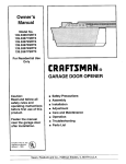
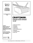
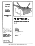
GARAGE DOOR OPENER
1/2 HP
Caution:
Read and follow all
safety rules and
operating instructions
before first use of this
product.
Fasten the manual
near the garage door
after installation.
Compffeswith UL325/Ih
re_lations effective
January
= Safety Precautions
a Assembly
= Installation
= Adjustment
[] Care and Maintenance
= Operation
,, Troubleshool_y:
= Parts List
_
1, I9_3
.
ii
Sears,
Roebuck
and Co,
Hoffman
Estates, IL 60179
U.SoA.
i
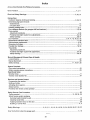
Contents
ill
i
Page
Contents
Page
A review of safety alert syrnboFs........................................
2
lnstalt Me lights and lenses ..................................... !9
You'll need tools ...............................................................................
3
Attach emergency release rope and handle ........... 19
Safety information regarding garage door
ElectdcaJ requirements ................................................ 20
locks and ropes .............................................................
3
Safety reversing sensor information ....................... -21
Testingyourgaragedoorforsticking,
Install the safety reversing sensor ..........................
22, 23
bindingand baJance...............................................................
3
Fasten door bracket (sectional door) .........................
+24
lllustrat_on
ofsectional
doorinstaJlaUon
......................
4
Fasten door bracket (one-piece door) .......................25
lllustraUon
ofone-piecedoorinstaflation
......................
5
Connect door arm to trolley (sectional door) .......... .26
Cartoninventory
...............................................................
6
Connect door arm to U'otley (one-piece door) ......... -27
Hardwareinventory
......................................................
7
Adjustment section - pages 28 - 30
Assembly section - pages 8 - 1'1
Assemble T-rail ............................................................
Travel limit adjustments
8
Force adjustments
Attach cable pulley bracket ..............................................8
Install trolley ...............................................................
9
Fasten T-rail to opener ................................................
9
Install chain/cable
Test the safety reverse system .... ;............................. 30
Care of your opener .......................................................
10
Opera+Jon of your opener ...........................................
section +pages 11 - 27
Receiver
door .......................................................
and remote control programming
32
................. 33
Having a problem? ............................................... 34, 35
12
One-piece door ......................................................
t3
Install the header bracket ....................................... 14
Attach the T-rait to header bracket .............................
15
Position the opener ................................................. 16
Repair parts, rail assembly ...........................................
36
Repair parts, inst_lation ...............................................
36
Repair parts, opener assembly ..................................
Accessories ..................................................................
37
38
Index ..............................................................................
39
How to order repair parts ...............................................40
Hang Me opener .......................................................
17
Install the door control ............................................. 18
Start by Reviewing
31
Maintenance schedule ....................................................... 31
Installation safety instrucUons ................................. 11
Determine header bracket IocaUon
Sectional
......................................................... 29
Operation safety instructions ...................................... 31
Tighten the chain and cable ...............................................
11
Installation
28
Test the safety reversing sensor ............................... 30
10
.......................................................
Attach sprocket cover ..............................................
...........................................
Maintenance agreement ............................................ 40
Warranty ....................................................................... 40
these Important
+____
Safety Alert Symbols
i
i
,
, ,,,,,,,,,
,, ,,,
When you see these Safety Symbols on the following pages, they'will alert you to the possibility of
serious injury or death if you do not comply with the corresponding instructions.
The hazard may
come from something mechanical or from electric shock+ Read the insb'uctions
carefully+
Electrical
When you see this Sa'_'WSymbel.-)on,.the following pages, it will a ert you to the possibility of damage
..to+.,yg__ur
garage {]+6+O1
" andloi_.-theegarage cIoor opener if you do not comply with the corresponding
mstructton_+ Read+ttte mstruction+_'caretuJly...__
t]:,+ :,+++
-+,.+,
+++,
...... ++i
+_+_+_+_+
++.+i++!I,.JIIi+_'+S.'.++++%:++_,:+++++.++++.++++;.'!_+:+:_+++++_+
+#i+:+5:.+_++
++#
+++++-I
+
+
+t
....
r
......
..........
i
ii +
i'
iii
I
ii,
ii
i
*
i
This garage door opener is designed and tested to offer safe service provided it is installed, operated,
maintained and tested in strict accordance with the safety instructions
contained in this manual.
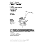
You'll Need Tools
During assembly, installation and adjustment of the opener, instructions will call for hand tools shown below
Per'<_
Hac_ Saw
Tape Measure
Claw Hammer
S_e_adder
i
,
i
i
i
A_ustable
i
End Wtenc_
i,i
An unbalanced garage door might not reverse
when required and someone under the door
could be seriously injured or killed.
If your garage door binds, sticks or is out of
balance,
call for professional
garage door
service. Garage doors, door springs, cables,
pulleys, brackets and their hardware are under
extreme tension and can cause serious injury
or death. Do not try to loosen, move or adjust
them yourself!
Ropes left on a garage
door could cause
someone
to become
entangled
and killed.
Remove all ropes connected to the door before
installing and operating the opener.
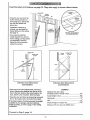
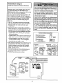
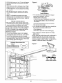
Identify the type and height of your door and any
special conditions that exist and any additional
materials that may be required by referring to the lists
on page 4 or page 5
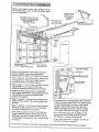
SECTIONAL DOOR
To avoid damage to the garage door and
opener, disable locks before installing and
operating the opener. Use a wood screw or nail
to hold locks
in the "open"
(unlocked)
position.
Operation at other than 120V 60 Hz will cause
opener malfunction and damage.
=mN ,,,
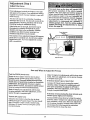
Before you begin, complete the following test to
make sure your door is balanced, and is not
sticldng or binding:
. Uft the door about halfway as shown. Release the
door. It shoul_l stay in place, supported entirely by
its spdngs.
• Raise and lower the door to see if there is any
binding or sticking.
I
ONE-PtECE
DOOR
..............
.
..
...........
:.,_. ........
.
_
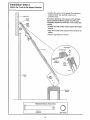
Before you begin, survey your garage area to
see whether any of the conditions below apply
to your installation.
Slack in Chain Tension
is No_
When
Garage Door is Clo_ed
Extension
Sp_ing
OR
Access Door
0
Safety Reversing
Sensor
.
Header
Closed Position
Ca_e Pulley
Rail A.'_embly
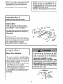
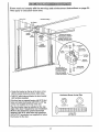
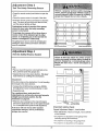
Based on your particular requirements, there are
several installation steps which might call for
matedaJs and/or hardware not included in the carton.
• Step 1, page 12 - Look at the wall or ceiling above
the garage door. The header bracket must be
securely fastened to structural supports.
--
Emerger, cy Release
Rope & Handle
. Step 5, page 17 - Do you have a finished ceiling in
your garage? If so, a support bracket and
additional fastening hardware may be required.
oSafety reversing sensor, page 2t - Depending
upon garage construction, wood blocks may need
to be {astened to mounting locations before
sensors are installed.
• Step 10, page 22 - Alternate floor mounting of the
safety reversing sensor will require hardware not
provided.
• The opener can be installed within 2 feet to the left
or dght of the door center if there is a torsion spdng
or center bearing plate in the way of the header
bracket or door bracket area. If your door has
extension spdngs, the opener must be installed
in the center of the door. See pages 12 and 24.
° Step 11, page 24 - Do you have a steel, aluminum,
fiberglass or glass panel door? if so, horizontal
and vertical reinforcement is required°
• Look at the garage door where it meets the floor.,
It must close on the floor al! the way across.
Otherwise, the safety reverse system may not
work properly. See page 3& Floor or door should
be repaired.
You may find it helpful
• Do you have an access door in addition to the
garage door? If not, Model 53702 Emergency
Key Release is require& See page 38°
- If your door is more than 7 feet high, see the rail
extension kits listed on page 38.
to refer back to this page as you proceed with the installation
4
of your opener.
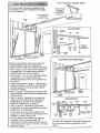
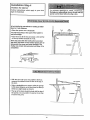
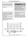
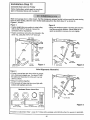
Based on your particular requirements, there are
several instaJlat_on steps which might call for
materiaJs and/or hardware not included in the carton.
'. Step 1, page 13 - Look at the wail or ceiling above
the garage door. The header bracket mustbe
securely fastened to structural supports°
• Step 5, page 17 - Do you havea finished ceiling in
your garage? If so, a support bracket and
additiona! fastening hardware (not supplied) may
be required.
• Safety reversing sensor, page 21 - Depending on
garage constn_ction, wood blocks may need to be
securely fastened to mounting locations before
sensors are installed.
• Step 10, page 22 -Altemate floor mounting of the
safety reversing sensor will require hardware that
is not provided.
• Step 11, page 25 - Generally, a one-piece door
does not require reinforcement. If your door is
lightweight, you can refer to the information
relating to sectional doors on page 24.
• Step 11, page 25 - Depending on your door's
construction, you might need additional mounting
hardware for the door bracket.
• Do you have an access door in addition to the
garage door?. If not, Model 53702 Emergency Key
Release is required° See page 38.
• The gap between the bottom of the garage
door and the floor cannot exceed 114".
Otherwise, the safety reverse system may not
work properly. See page 30. The floor or the door
should be repaired.
Safety
across width of door
_r
Closed Position
Cable
Bracket
Cable
Trolley
Ch_Jtl
I
T-rail
Bracket
Door
Straight
Door
Arm
Ernetgency Retease
Rope & Handle
You may find it helpful to refer back to this page
as you proceed with the installation of your
opener.
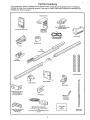
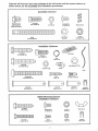
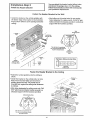
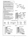
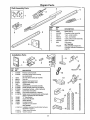
Carton
Inventory
Your garage door opener is packaged in two cartons which contain aJl parts illustrated below.. If anything is
missing, carefully check the packing matedaJ. Parts may be "stuck = in the foam. Hardware for assembly and
installation is shown on page 7o
Model 53675 on{y
Premium
Coetr_
Console
SECURITY+
M Lfft_Fur'_;'*,JQn
SECURITY+
Three-Function Retake Conm:_l
w_ V'_,_r C_lp (2)
=
..,._'_
Key{ess Entry
Ught Lens (2)
Wh_e & W'_e/Red
2-Cooduc_r
BeLlWire
H_'tging
Safety Revering Sensor
Mounling Bracket
W_thSquare Holes (2)
Bt-ackets
oI
oI
Curved Door
Arm Section
Safety Reversing Sensor
Mounting Bracket
With S{ot (2)
{2) Safety Reversing Sensors
(1 Sendrng Eye and I Receiving Eye)
with
2_,onductor White & Wh_tefBEack Bell W_re
attached
el
Safety Labels
and
LJtet"dluce
Straigh_ Door
Ann Section
Separate all hardware
from the packages
in the rail carton and the opener
shown below, for the assembly
and installation
procedures.
Assembly
Waslkei'ed
Screw
Hardware
Hex Screw
5/16"-18xl/2" (2)
{rilotlnted _i opene[)
5/16*-18x7fS"
carton,
4
Nut
(3)
as
C_-riage Bolts
1t4"-20×1/2" (4}
5./16%18 (5}
Ma_erUnk(2)
©
©
Loc_ Nut
114"-20x7tt6" (4)
Lo_ Wmsher
Trolley
Threaded
Shall (1)
5/_6"(4)
Installation Hardware
RaJI Grease
Ring
Faslener(3)
L_g Screw
5/16"-18xl-7/8"
(2)
Rope
Carnage Boll
5/16"_18x2-I/2"
(2)
oll
Clevis Pin
5/16"x2-3_4" (I)
Clevis Pin
5/16"x1-1t4"
i
iiiiii
ii
Hill
Clevis Pin
(1)
5/16*x1"
(I)
ktsu_led
Stales
I II,INIIN.Ill
ii
i ININ
Safety Reversing Sensor
Installation
Hardware
Lock Nut
1/4x1-112" (4)
Carriage Bolts
l14"4_0x1,t_ (4)
1/4=-20 (4)
Hex Screw
114-20x 1-1/'2" (2 !
S_ew
t/t O-32x3t8 ° (4)
Lock Nut
t10x32 (4)
Wing Nut (2)
Insulaled
Staples (20)
(10)
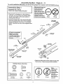
Assembly
To avoid
installation
Assembly
difficulties,
Section:
do not run the garage door opener until instructed
Step 1
Assemble
the T-raft &
Attach the Cable Pulley
Bracket
. Place the 3 T-rail sections on a flat surface for
assembly. The end sections are identical. Make
sure the "arrow label" on the center section is
pointing toward the doon
• insert the carriage
seat in the square
and pass through
section. Assemble
tighten.
Pages 8 - 11
Make sure bolt necks are
seated In the square
holes and rails are
aligned before you
tighten lock nuts, (See
right and wrong views).
Improper assembly can
cause jerky trolley
operation, noise and/or
nuisance door reversals.
Right
to do so.
Wrong
bolts so the square bolt ned_
holes in the T-rail end sections
the round holes in T-rail center
lock nuts, ensure alignment and
t/4" Lock Nut
Q
If Trail is not assembled
EXACTLY as shown,
!trolley wilt not travel
smoothly along length of
rail or it will hit against
the nuts.
\
Ca_{e putIeybracket
at_ches Io FRONT
END of T-r_]
T-RAIL FRONT
(TO_oon)
• Posi_on the cable puiley bracket on the front end of the
T-rail as shown_ Fasten securely with the hardware.
Hardware Shown Actual Size
©
Lock Nut
1/4"-L_xT/16"
Hex $_mv
_I 6"-1BxT/8"
O
Carnage Bolts
114"-20xl _"
Nut
_16 %18
Lc<:k Washer
_16"
Right
Wrong
When
tightening the
screws, be
sure to keep
bracket parallel
to the rail.
Otherwise, the
rail may bow
when opener is
operated.
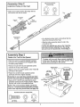
Assembly
Install
Hardware Shown
Actual Size
Step 2
the Trolley
on the T-rail
©
• Attach the threaded shaft to the trolley with the
lock washer and nuts as shown°
Lo_ W_he
5/16"
r
NuI
Trottey
=J16"-18
Lock Washer
5/16"
Inner Nut
5/16"
T_ey
- As a temporary stop, insert a screwdriver into the
hole in the front end of the T-rail.
• Slide the trolley assembly along the rail to the
screwdriver stop.
If trolley hits against any nuts on the T-rail, the
bolts and nuts were attached from the wrong
side and must be repositioned.
Review Step 1.
Fasten the T-rail
to the
Assembly
Step
3
!
Opener
• Place the opener on packing material to protect
the cover,, For convenience, put a support under
the cable pulley brackeL
To fasten rail, use only those screws mounted
in the top of the opener. Any other screws will
c_use seriou_ damage to the opener,
• Remove the (2) 5/16"-18xl/2" washered screws
mounted in the top of the opener.
• Align the holes in the back section of the T-rail with
the holes in the opener.
• Fasten the rail with the (2) washered screws
previously removed. Tighten securely.
Remember to use only these screws! Any other
screws will cause serious damage to the opener.
• Insert a 5/16=-18x7/8" hex screw into the cover
protection bolt hole in the T-rail as shown° Tighten
securely with a 5/16" lock washer and nut.
NOTE: This screw prevents trolley over-travel.
Keep a 2" minimum between the trolley and this
screw when adjusting travel limits (see page 28).
Hardware
Hex Screw
5/16""18_718_
Shown Actual Size
Nul
5/16"
Lock Washer
5/16"
u UmHHHHmiin=,
Hex Screw
5/16_-18x7/8 •
Cover
Protection
T-ran
(Back Section).
5/16"-18
Assembly
Step 4
Install
the Chain/Cable
Attach
the Sprocket
&
Cover
1
entangled tn moving opener sprocket. Attach
sprocket cover securely, Never operate opener
I Serious
Injury
result
If fingers
become I
while your
hand can
is near
the opener
sprocket.
Dispensing C,arlc,r_
Opener
Figure
Leave Chain and Cable
2
sp_t
{nside Dispensing
Carton to Prevec_t K3nking,
Kee_ Cha;n and Cable
Taul When Dispensing
• Detach the cable loop from the carton and fasten it
to the trolley with a master tink from the hardware
bag. See master link procedure, Figure 1.
• With the trolley against the screwdriver, dispense
the cable around the putley.
Figure 3
o Proceed back around the opener sprocket,
Figure 2. Be sure sprocket teeth engage the chain.
Continue forward to the trolley threaded shaft,
Figure 3.
• Use the second master link to connect the
chain to the flat end of the shaft. Check
Master
to make sure the chain is not
twisted.
Master U_
Ctip-On Spring
,
Mas_er
Unk Cap
Ra[ End
of Trolley
Threaded Shaft
Chin
• Remove the screwdriver.
Cable
Loop
Master Link Procedure:
Push pins of master link bar
through cable loop and hole tn
front end of tce[ley. Push cap
over pins and past notches,.
Slide cJip-on spring over cap
and into notches until both
Sprocket
Cover
Slot
pins are securely" locked.
Top o! Opener
To attach the sprocket
cover:
• _nsert the back tab in the opener slot. Squeeze the
cover slightly and insert the front tab in the slot on
the mounting plate.
10
Assembly
_ghten
Step 5
the Chain & Cable
Loc_
• Spfn the inner nut and lock washer down the
threaded shaft, away from the trolley.
Outer Nul
To T_ghten O,.er
Nut
Washer
_
lnne'r Nut
--\
/
• To tighten the chain, turn outer nut in the direction
shown. As you turn the nut, keep the chain
from twisting.
When the chain is approximately 1/2" above the
base of the T-rail at its midpoint, re-tighten the
inner nut to secure the adjustment
Sprocket noise can result if chain is either too
loose or too tight
When installation
chain droop with
the chain returns
door is open, do
Cha_
I
is complete, you may notice some
the door closed. This is normal. If
to the pos_en shown when the
not re-adjust the chain°
1£2Inch
I
NOTE: During future maintenance, ALWAYS
pull the emergency release handle to disconnect
trolley before adjusting chain.
You have now finished
assembling
your garage door opener.
warnings
before proceeding
to the installation
section:
=,luJ,Hl!l ill,
Please read the following
,i
'11 I I
I
'1
I
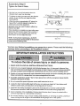
IMPORTANT INSTALLATION
I'l'l'lllllq
I
'14
I
'!
I
I
--
i
................
INSTRUCTIONS
To reduce the risk of severe injury or death to persons:
1. READ AND FOLLOW ALL INSTALLATION
INSTRUCTIONS.
2. Install only on a properly balanced and lubricated garage door. An improperly balanced door
may not reverse and could result in severe injury or death. Repairs to cables, spring assemblies
and other hardware must be made by a professional service person before installing opener.
3. Disable all locks and remove all ropes connected to the garage door before installing
Ropes connected to a garage door can cause entanglement
and death.
4, If possible, install door opener 7 feet or more above floor with the emergency
mounted 6 feet above the floor.
5. Do not connect the opener to power source
until instructed
the opener.
release handle
to do so.
6. Locate the Door Control within sight of the door at a minimum height of 5 feet where small
children cannot reach, and away from all moving parts of the door.
7. Install the User Safety Instruction Label on the wall adjacent to the door control and the
Maintenance Instruction Label in a prominent location on the inside of the garage door.
8. Upon completion of the installation, the door must reverse when it comes in contact with a
one-inch high object or a 2x4 laid flat on the floor.
9. Do not wear watches, rings or loose clothing while installing or servicing an opener. Jewelry
loose clothing can be caught in the mechanism of the garage door or the opener°
11
or
Installation
•
=,
Installation
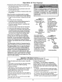
Determine
L
Section:
,,,
Step 1
Header
Bracket
Location
if the header bracket is not rigidly fastened to
a structural
support
on the header wall or
ceiling, the safety reverse system may not
work properly (see page 30). The door might
not reverse when required, and could cause
serious iniury or death.
Installation procedures vary according to
garage door types. Follow the instructions
which apply to your door.
,= = ,==
...........................
_de_
Pages 12 - 27
, H,
VertJc_
GuideSne
__ FinL_hed__
Ceiling
The garage
door springs, cables, pulleys,
brackets and their hardware are under extreme
tension.
Do not attempt to loosen, move or
adjust them yourself. Serious personal injury
or death could result. Call for professional
garage door service.
II=I,Hiii=
,,, Hill,
=
,ll,=
WaM
- Close the door and mark the inside
vertical centedine of the garage door.
• Extend the line onto the header wail
above the door°
Remember, you can fasten the
header bracket within 2 feet of the
left or right of the door center only if
a torsion spring or center bearing
plate is in the way; or you can attach
it to the ceiling (refer to page 14)
when clearance is minimal. (it may
be mounted on the wall upside down
if necessary, to gain approximately
1/2".)
ff you need to install the header bracket
on a 2x4 (on wall or ceiling), use lag
screws (not supplied) to securely fasten
.the 2x4 to structural supports as shown
here and on page l&
.J
• Open your door to the highest
point of travel as shown. Draw
an intersecting horizontal line
on the header wall 2" above
the high point. This height will
provide travel clearance for the
top edge of the door.
Door clearance brackets are
available for sectional doors
when headroom clearance is
less than 2"o See accessory
page 38.
Sectional door
with curved track
Proceed
to Step 2, page t4.
£
12
One-piece door
with horizontal track
Pead the Safety
instructions
on page 12. They also apply to doors
Header
withm_t
tracks.
Wall
2x4
• Close the door and mark the
inside ve_c_t centedine of
your garage door. Extend the
fine onto the header wall
above door.
If headroom clearance is
minimal, you can install the
header bracket on the ceiling°
See page 14.
• If you need to install the
header bracket on a 2x4 (on
wall or ceiling), use lag screws
(not supplied) to securely
fasten the 2x4 to structural
supports as shown.
Header WalJ
/
Highest Point
of Travel
Jamb
Haxdware
ii
One-piece door without track
jamb hardware
One-piece door without track
pivot hardware
EXAMPLE
° Open your door to the highest point of travel as
shown. Measure the distance from the top of the
door to the floor. Subtract the actual height of the
door. Add 8" to the remainder. (See Example),
Distance from top of door
(at highest point of travel) to floor ............................ 92"
Actual height of door ................................................ -88"
Remainder ..................................................................
4"
• Close the door and draw an intersecting horizontal
line on the header wall at the determined height.
Add ....................................................
+8"
If the total number of inches exceeds the height
available in your garage, use the maximum
height possible, or refer to page 14 for ceiling
installation.
Proceed
Bracket height on header wall ............................... =12"
(Measure UP from top of CLOSED door)
to Step 2, page 14.
13
Installation
Install
I
Step 2
the Header
Bracket
Fasten
the Header
• Center the bracket on the vertical guideline with
the bottom edge of the bracket on the horizontal
tine as shown (with the arrow pointing toward the
ceiling),
_
You can attach the header bracket either to the
wall above the garage door, or to the ceiling.
Follow the Instructions
which will work best for
your particular requirements.
Bracket
to the Wall
• Mark either set of bracket holes (do not use the
holes designated for ceiling mount). Drill 3/16" pilot
holes and fasten the bracket securely to a structural
support with the hardware provided.
Header
Wall
Hardware
Highest
Point of Travel
Shown Actual Size
Vertical
Center
Line
(_f Garage Door)
Lag Screw
5/16"-9xl -5/8"
Fasten the Header
Bracket
to the Ceiling
• Extend the vertical guideline onto the ceiling as
shown,
• Center the bracket on the vertical mark, no more
than 6" from the wail Make sure the arrow iS
pointing toward the wall. The bracket can be
mounted flush against the ceiling when clearance
is minimal,
• Mark holes designated for ceiling mount only. Drill
3/16" pilot holes and fasten bracket securely to a
structural support with the hardware provided.
Doo_
Ceiling Mounting Holes
Spdng
._Header
Wall
The hall hole isfor positioning onty
You must use tag screws to mounl
the header bracket
14
Installation Step 3
Attach the T-rail to the Header Bracket
• Position the opener on the garage floor below the
header brackeL Use packing material as a
protective base.,
If the door spring is in the way you'll need help.
Have someone hold the opener securely on a
temporary support to a!low the T-rail to clear the
spring,
• Position the cable pulley bracket against the header
bracket.
• Align the bracket holes and join with a clevis pin as
shown.
° Insert a ring fastener to secure.
Ring Faslener
Header Bracket
Bracket
Tempom_3,
Support
Hardware Shown
Actual Size
°B
C!evis Pin
5/16";{2-3/4"
©
Ring Faslener
H IH,
!5
H,H
w
.........
Installation
Position
Step 4
the Opener
=ollow Instructions
type as illustrated.
which apply to your door
A 2x4 laid flat Is convenient for setting an ideal
door-to-T-rail distance.
• Raise the opener onto a stepladder.
You will need help at this point ff the/adder
not tall enough.
is
• Open the door aJlthe way and place a 2x4 laid flat
on the top section beneath the T-raiL
Door
If the top panel hits the trolley when you raise
the door, pull down on the trolley release arm to
disconnect the inner and outer sections. The
trolley can remain disconnected
completed.
until Step 12 is
• With the door fully open and parallel to the floor,
measure the distance from the floor to the top of
the door.
Top of Opener
• Using a stepladder as a support, raise the opener
to the same distance as the door from the floor (it
will be at a slight angle as shown).
o The top of the door should be level with the top of
the opener. Do not position the opener more than
2" above this point.
16
installation
Hang
Step 5
the Opener
Two representative
installations are shown.
Yours may be different. Hanging brackets should
be angled, Figure 1, to provide rigid support. On
inished ceilings, F_gure2, attach a sturdy metal
bracket to structural supports before installing the
opener. The bracket and fastening hardware are not
supplied. See accessory page 38.
Figure I
• Measure the distance from each side of the opener
to the structural support.
= Cut both pieces of the hanging bracket to required
lengths.
• Drill 3/16" pilot holes in the structural supports.
• Attach one end of each bracket to a support w_th
5/16"-18xl-7/8'
lag screws.
- Fasten the opener to the hanging brackets with
5/16=-18x7/8" screws, lock washers and nuts.
• Check to make sure the T-rail is centered over the
door (or in line w_ the header bracket if the
bracket is not centered above the door).
• Remove the 2x4. Operate the door manually. If the
door hits the rail, raise the header bracket.
Figure 2
H_dden
Hardware Shown Actual Size
L_ Screw
5/16"-18xt -7/8"
Hex Screw
5/16"- t6x7/8"
Nu[ 5/16%18
Lock W_het
5,/'_6_
,l=
,,, II,L==I,
"f7
=
"
"_'r
•
installation
Install
,ll
i
Step 6
the Premium
Control
Console
k
Locate the door control within sight of the door
at a minimum height of 5 feet where small
children cannot reach, and away from all moving
parts of the door and door hardware.
The door control is typically attached directly to the
wall If installing into drywall, ddll 5/32" holes and
use the anchors provided. For pro-wired installations
(as in new home construction), Console models
may be mounted to a standard single gang box
(Figure 2).
Do not connect to five ele_cal
_rlng. Connect
only to 24 Volt low voltage wires. Connection to
live wires or higher voltage may cause serious
injury from shock, burn or electrocution.
Children operating or playing with a garage
door opener can Injure themselves or others.
The garage door could close and cause
serious injury or death.
Install the door control (or any additional push
buttons) out of the reach of children and away
from all moving parts of the door and door
hardware, but where the garage door Is Wsfble.
Do not allow ¢h|Idren to operate the push
button(s) or me remote control(s).
1 .Stdp 1/4" of insulation from one end of the bell
wire and connect it to the two screw terminals on
the back of the door control: white to 2, and
white/red to 1.
A moving garage
under it. Activate
door is properly
clearly, and there
travel.
2. Pry off cover along one side with a screwdriver
blade (see Figure 1). Fasten with 6ABxl-1/4" selftapping screws (standard installation) or 6-32x1"
machine screws (pre-wired installation) as follows:
door could.injure someone
the opener only when the
adjusted,
you can see it
are no obstructions to door
Hardware Shown Actual Size
• Install bottom screw, allowing 1/8" to protrude
above wall surface.
• Position bottom of door control on screw head and
slide down to securer Adjust screw for snug fit.
Insulted
S_es
Comtol Console (bidir,_-taJlat.i(xr_)
• DdU and install top screw with care to avoid
cracking plastic housing. Do not overtighten.
. Insert top tabs and snap on cover
DryWa_,,_,ncho_
3. (For standard installation) Run the bell wire up the
wall and across the ceiling to the opener. Use
insulated staples to secure the wire in several
places. Be careful not to pierce the wire with a
staple, creating a short.
4. Connect the bell wire to the terminal screws on
the opener panel: white to 2; white!red to 1.
5. Position the antenna wire as shown.
Figure
1
Figure 2
REMOVE & REPLACE COVER
pRE-VvlRED
INSTALLATION
To Replace,
_._To
R_'nove,
Insert
._'_,TwisI
Top Tabs
*" ['P_/']r_'i
J Here
24 Volt
2-G_nductor
BellWire
!
O
/
Ught
Lc_k
PREMIUM
CONTROL
CONSOLE
18
6_Attachthe UserSafetyInstruction
labeltothewall
nearthedoorcontrol,andtheMaintenance
Instructionlabelin a prominent
tocai_on
onthe
insideofthe garagedoor.
Page 32 explains
how to use the door control.
Installation
Install
Step 7
the Lights
n
Do NOT connect
the power and operate the
openerat
this time. The trolley will travel to the
full open posltlon
but will not return to the
close
position
until the sensor
beam is
connected and properly aligned.
See Safety Reversing
Sensor instructions
beginning on page 21.
and the Lenses
i
nl
i nil
n I
i Ul u
i
i
I u
II
i
Install the lights:
• Install a 75 watt maximum light bulb in each
socket. The lights will tum ON and remain lit for
approximately 4-1/2 minutes when power is
connected. Then the lights will turn OFF.
o If the bulbs bum out prematurely due to vibraUon,
replace them with standard neck "Garage Door
Opener = bulbs.
Install
the lenses:
Lens
"Cab
* Apply slight pressure on the sides of each lens
and slide the tabs into the slots in the side panels.
. For convenience, the lenses may be installed
after Adjustment
Step 4 on page 30.
T_b
.. Reverse the procedure to remove _e lenses.
Installation
Step 8
Attach the Emergency
Release Rope and Handle
Do not use the red handle to pull the door
open or closed. The rope knot could become
untied and you could fall, Use the emergency
release only to disengage the trolley and, if
possible, only when the door is closed.
i
• Thread one end of the rope through the hole in
the top of the red handle so "NOTICE" reads right
side up as shown. Secure with an overhand knot.
Garage doors are heavy. If the door is open
when the handle is pulled, the door could
close inadvertently
if it ts not properly
balanced. Serious injury may result to persons
under the door. Make sure the doorway is clear
of persons and obstructions
before pulling
handle when door is open.
The knot should be at least 1" from the end of
the rope to prevent slipping.
• Thread the other end of the rope through the hole
in the release arm of the outer trolley.
• Adjust rope length so the handle is 6 feet above
the floor. Secure with an overhand knot.
If it is necessary to cut the rope, heat seal the
cut end with a match or lighter to prevent
unraveling.
-
_t_======_
_OF.
.......
Overhand
" _
Knot
T_oliey
Rope --
Release Arm
_--R
Overhand
Kno_
19
Emergency
eiease Handte
....i
,,,,u,uJl
Installation
Electrical
Step 9
Requirements
To prevent electrocution
or fire, Installation
and wiring must be In compliance with local
electrical and building codes.
To reduce the risk of electric shock, your garage
door opener has a grounding type plug with a third
grounding pin_ This plug will onlyfit into a grounding
type cutlet..
Do NOTuse an extension cord, 2-wire adapter,
or change the plug In any way to make It fit
your outlet.
/
If the plug doesn_ fit into the outlet you have,
contact a qualified electrician to install the proper
outlet,
l
ilu== i
uHu==l
i
i,=
To avoM installation difficulties,
do not run the opener at this time.
Right
If permanent
=
ii=,,ll i
wiring
is required by your local
='=uLu=
i llll
,,,,,,,,,,,,,,,,,,,,
code, refer to the following
Wrong
procedure:
j
To prevent electrocution,
remove power from
the garage door opener and from the circuit
you plan to use for the permanent connection.
HHH=
==
_,H',U_
Permanent
HHH,=
Wiring
Connections
To make a permanent connection through the
718" diameter hole in the top of the opener
(according to local code):
Ground Tab
• Remove the opener cover screws and set the
cover aside.
G_een
• Remove the attached 3-prong cord.
Screw
• Connect the black (line) wire to the screw on the
brass terminal; the white (neutra!) wire to the
screw on the silver terminal; and the ground wire
to the green ground screw. The opener must be
grounded.
• Reinstall the cover.
To avoid installation difficulties,
do not run the opener at this time.
W_rB
1
20
B_ac_k
Wire
_,
The Safety Reversing
Information
you'll
need before
you begin
System
the installation
The safety reversing sensor must be connected
and aligned correctly before the garage door
opener will move in the down direction° This is a
required safety device and cannot be disabled.
of the safety
reversing
sensor.
Without a properly working safety reversing
sensor, persons (particularly children) could
be injured or killed by a closing garage door.
Read and follow all Instructions.
Installation procedures are the same for sectional
and one-piece doors.
To protect small children, install the safety
reversing sensor so that the beam will be no
higher than 4"-6" above the garage floor.
Disconnect power to the garage door opener
before installing the safety reversing sensor.
..................................
Be sure power to the opener is disconnected.
The sending eye transmits an invisible light beam to
the receiving eye. The units can be installed on
either side of the garage door as long as the sun
never shines directly into the receiving eye lens.
Look at the label on the connector end of each case
The brackets must be securely fastened to a solid
surface such as the studs on either side of the door,
or add a piece of wood at each location if installing in
masonry construction.
The invisible light beam path must be unobstructed°
No part of the garage door (or door tracks, spdngs,
hinges, rollers or other hardware) can interrupt the
beam while the door is closing. If it does, use a piece
of wood to build out each sensor mounting location to
the minimum depth required for light beam clearance.
to identify the sensors.
The brackets must be connected and fastened so
that the sending and receiving eyes face each other
as shown in Figure 1.
If an obstruction breaks the light beam while the
garage door is closing, the door will stop and
reverse to full open position and the opener lights
will flash for 5 seconds.
Sellsor Be_Brr_
4,.6" rr_,Xo
above floor
lnvlsit3e Ught Beam
Protection Area
Figure
i
1 : Facing the door from inside the garage
21
Installation
Step 10
" ---]
Figure
Figures 2 and 3 show assembly of brackets and
"C" wrap based on the recommended installation of
the sensors as shown on page 21.
2
Meurrdng B racJ_ t
W'_ Square Hoes
However, Figures 4 and 5 are variations which may
rr_your installation requirements better° Make sure
the wraps and brackets are aligned so the
sensors will face each other across the garage
door.
° Fasten the "C" wraps to the mounting brackets
ha,.4ng square holes, using the hardware shown
in Figure 2.
• Connect each assembly to a slotted bracket, using
the hardware shown in Figure 3o
Note the alignment of the brackets
right sides of the door.
Figure 3
for teft and
• Finger tighten the lock nuts.
° Use bracket mounting holes as a template to
locate and ddH (2) 3/16" diameter pilot holes on
both sides of the garage door, 4"-6" above the
floor but not exceeding 6; (See warning on
page 21 ,)
• Attach bracket assemblies with 1!4"x1-1/2" lag
screws as shown in Figure 3.
• Adjust right and left side bracket assemblies to the
same distance out from the mounting surface.
Make sure all door hardware obstructions are
cleared. Tighten the nuts securely.
114"-20
LockNtr_.s
Hardware Shown Actual Size
©
#10-32.x3/8 °
Screw
Figure
#10x_2
1/4"-20*zif2 °
LockNut
LagScrew
S_tes
4
1/4"÷20
Cania_e BOILS
Lock Nut
Figure 5
Alternate
Wall Mount
A|temate
Roor Mount
Sensorwith w_re
In_calor IJght
Mounting Bracket
wiLhSquare Holes
Mount_g Bracket
with Stot
Attach wiLh
¢onc_ele anchors
(net provided)
22
oCentereachsensorunitina "C"wrapwithlenses
pointingtowardeachotheracrossthedoor(see
_gure 6).
• Securesensorswiththehardwareshown°Finger
tightenthe wingnutonthereceiving eye to allow
Figure
6
for final adjustment. Securely tighten the sending
eye wing nut.
• Run the wires from both sensors to the opener.
Use insulated staples to secure wire to wall and
ceiling.
Trouble
o Strip 1/4" of insulation from each set of wires.
Separate white and white!black wires sufficiently to
connect to the opener terminal screws: white to 2
and white/black to 3.
Aligning
Shooting
1oIf the sending eye indicator light does not glow
steadily after installation, check for.
• Electric power to the opener.
• A short in the white or white/black wires. These
can occur under staples or at screw terminal
connections.
the Safety Sensors
• Plug in the opener. Green indicator lights in both
the sending and receMng eyes will glowsteadilyif
wiring connections and alignment are correct.
• Incorrect wiring between sensors and opener.
• An open wire (wire break).
2. If the sending eye indicator light glows steadily but
the receMng eye indicator light doesn't:
The sanding eye indicator light will glow regardless
of alignment or obstruction. If the indicator light is
off, dim, or flickering in the receiving eye (and the
invisible light beam path is not obstructed),
alignment is require&
• Check alignment.
• Check for an open wire to the receiving eye.
3. If the receiving eye indicator light is dim, realign
either sensor.
• Loosen the sending eye wing nut and readjust,
aiming directly at the receiving eye. Lock in place.
NOTE: When the invisible beam path is obstructed or
misaligned while the door is closing, the door will
reverse. If the door is already open, # will not close.
The opener lights will flash 10 times. (If bulbs are not
installed, 10 clicks are audible.) See page 21.
• Loosen the receiving eye wing nut and adjust
sensor vertically and/or horizontally until it receives
the sender's beam. When the green indicator light
glows steadily, tighten the wing nut.
23
i
,,i ,,ll,
ii,ll i
Installation
Fasten
Step 11
Door Bracket
Follow Instructions
which apply to your door
type as illustrated below or on page 25.
ILl,
Ill,
A horizontal brace should be long enough to be secured to 2 vertical
cover the height of the top panel.
supports.
A vertical
brace should
The Illustration shows one piece of angle iron as the horizontal brace. For the vertical brace, 2 pieces of
angle tron are used to create a "U"-shaped support. The best solution is to check with your garage door
manufacturer
for an opener Installation door reinforcement
kit,
Figure I
Figure
Inside Edge
of Door or
Reinforcement Board
%
o Center the door bracket on the previously marked
vertical guideline used for the header bracket
instaJlation° Note correct UP placement, as
stamped inside the brackeL
Door Bracket
• Position the bracket on the face of the door within
the following limits:
Hardware Shown Actual Size
A) The top edge of the bracket 2"-4" below the top
edge of the door.
B) The top edge of the bracket directly below any
structural support across the top of the door°
• Mark and drill 5/16" left and right fastening holes.
Secure the bracket as shown in Figure 1 if there is
vertical reinforcement.
Nut 5/16-I 8
If your installation doesn't require vertical reinforcement but does need top and bottom fasten{ng holes
for the door bracket, fasten as shown in Figure 2.
HH
24
L_
Washer 5/16 =
2
P'.ease read and comply
They apply to one-piece
1
with the warnings
doors also.
and reinforcement
instructions
on page 24.
2x4 Support
1
Vertical
Cente_neof
Ooor
I
• Center the bracket on the top of the door, in line
with the header bracket as shown. Mark holes°
Hardware Shown Actual Size
• Drill 5/16" pilot holes and fasten the door bracket
with hardware supplied.
© ©
If the door has no exposed framing, drill 3/16" pilot
holes and fasten the bracket with 5/16"x1-112" lag
screws (not supplied) to the top of the door.
Nut 5/16"-18
The door bracket may be installed on the top
edge of the door if required for your installation.
(Refer to the dotted line optional placement
drawing.) Drill 3/16" pilot holes and substitute
5/16"x1-112" lag screws (not supplied) to fasten
the bracket to the door.
25
Loc_ washer 5/16"
Installation
Connect
Step 12
Door
Arm to Trolley
Follow Instructions
which apply to your door
type as tUustrated below and on page 27.
ll,lllllll i Ill
Ill
:"
Make sure garage door is fully closed, Pull the emergency release handle to disconnect the outer trolley
from the inner trolley, Slide the outer trolley back (away from the door) about 2" as shown in
Figures I, 2 and 3.
Figure 1:
Figure 2:
- Fasten straight door arm section to outer trolley
with the the 5/16"x1" clevis pin. Secure the
connection with a ring fastener.
- Fasten curved door arm to the door bracket in the
same way, using the 5/16"xl-1/4"c/evispin.
• Bring arm sections together. Find two pairs of holes
that line up and join sections. Select holes as far
apart as possible to increase door arm rigidity°
Inner Trotley
Fastener
/
Ring
tlI
_
16_I-
_
lol -- S_ght
iP!
,u
Curved
Figure 1
5_'16"x1-114"
Hole Alignment
Alternative
Figure 3:
- if holes in curved arm are above holes in straight
arm, disconnect straight arm. Cut about 6" from
the sol{d end. Reconnect to trolley with cut end
down as shown.
- Bring arm sections together.
° Find two pairs of holes that line up and join with
screws, lock washers and nuts.
Hardware Shown Actual Size
© ©©
Nut 5/16"-18
Lock Washer 5/16"
•
o
C_ev[s P_n
Clevis Pin
5/16"xI' 0"roIley)
5t'16_xl-lt4
Proceed to Adjustment
_ Cu! Th_sEnd
Ring Fastener
° (Door Bracket}
Figure 3
Hex Screw
5/16'-18x7/8"
Step 1, page 28_ Trolley wilt re-engage
26
automatically
when the opener is operated.
Assemble
the Door Arm:
Ooor
• Fasten the straight and curved door arm sections
together to the longest possible length, w_ a 2 or 3
hole ovedap.
Rir_g
Brad<or _.j_,-_JO-----
Fastene r
• With the door closed, connect the straight door arm
section to the door bracket with the 5-16" × 1-1/4'
clevis pin.
• Secure with a ring fastener°
DoorArm
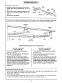
On one-piece doors, before connecting the door arm to _qe trolley the travel limffs must be adjusted. Umit adjustment screws are located on the left side panel as shown on page 28. Follow adjustment procedures below.
__L__
'
Closed
II
Door
I
Open Door
Door Arm
Ooo_w_
I
E.ack'watd Slant
Adjustment
Procedures for One-Piece
Open Door Adjustment:
Decrease UP limit
Doors
Closed Door Adjustment:
Decrease DOWN limit
• Turn the UP limit adjustment screw counterclockwise 5-t/2 turns,
• Turn the DOWN limit adjustment screw clockwise
5 complete tums_
• Press the Wall Control push bar. The trolley will
travel to the fully open position.
* Press the Wall Control push bar° The trolley will
travel to the fully closed position.
• Manually raise the door to the open position
(parallel to the floor), and lift the door arm to the
trolley. The arm should touch the trolley just in
back of the door arm connector hole. Refer to the
fully open trolley/door arm positions in the
illustration. If the arm does not extend far enough,
adjust the {imit further. One full tum equals 2" of
trolley travel.
• Manually close the door and lift the door arm to the
trolley° The arm should touch the trolley just ahead
of the door arm connector hole. Refer to the fully
closed trolley/door arm positions in the illustration° If
the arm is behind the connector hole, adjust the limit
further° One full turn equals 2" of trolley travel.
Connect
the door arm to the trolley.
• Close the door and join the curved arm to the connecter hole in the trolley with the remaining clevis pin. It may
be necessary to lift the door slightly to make the connection.
•Secure with a ring fastener_
• Run the opener through a complete travel cycle If the door has a slight "backward" slant in full open position
as shown in the illustration, decrease the UP limit until the door is parallel to the floor
27
Adjustment
Adjustment
Adjust
Section:
Pages 28 -30
Step 1
the UP and DOWN Limits
Do not make any limit adjustments until the
safety reversing sensors are completely
installed_
Improper adjustment of the travel limits will
interfere wlth the proper
operation
of the
safety reverse system. The door might not
reverse properly
when required and could
seriously injure or kill someone under it. Test
the safety
reverse
system following
all
adjustments to the travel limits. See page 30.
Limit adjustment settings regulate the points at
which the door will stop when moving up or down.
=,=
The door will stop in the up direction if anything
interferes with door travel The door will reverse in
the down direction if anything interferes with the
door travel (including binding or unbalanced doors).
= =m,=
To operate the opener, press the Door Control push
button,. Run the opener through a complete travel
cycle.
• Does the door open and close completely?
• Does the door stay closed and not reverse
unintentionally when fully closed?
If your door passes both of these tests, no limit
adjustments are necessary unless the reversing test
fails (See page 30).
CQvaf
d
i0o
....°I1
ProtecSon
Bdt
13mit Adjustment
Adjustment
procedures are outlined below. Run
the opener through a complete travel cycle after
each adjustment.
Screws
Repeated operation of the opener during
adjustment procedures may cause the motor to
overheat and shut off. Simply wait 15 minutes
and try again.
Adjustment
Label
Read the procedures carefully before proceeding to
Adjustment Step 2o Use a screwdriver to make limit
adjustments.
How and When to Adjust the Limits
• If the door does not open completely,
opens at/eastfive
feet."
but
If you have adjusted the door arm to the maximum
length and the door still will not ctose completely,
lower the header bracket. See Installation Step 1,
pages 12 and 13.
Increase up travel. Turn the UP limit adjustment
screw clockwise. One hJm equals 2" of travel.
NOTE; To prevent the trolley from hitting the
cover protection
bolt, keep a minimum distance
of 2-4" between the trolley and the boil
o If the opener reverses in fully closed position:
Decrease down travel. Turn the DOWN limit
adjustment screw clockwise. One turn equals 2" of
travel.
• If door does not open at least 5 feet:
Adjust the UP (open) force as explained in
Adjustment Step 2_
• If the door reverses when closing and there is
no visible interference to trevel cycle:
• If the door does not close completely:
increase down travel Turn the DOWN limit
adjustment screw counterclockwise_ One turn
equals 2" of travel
If the opener lights are flashing, the Safety Reversing
Sensors are either not installed, misaligned, or
obstructed. See Troubleshooting, page 23.
Test the door for binding: Pull the manual release
handle. Manually open and close the door. tf the door
is binding, call for garage door service. If the door is
not binding or unbalanced, adjust the DOWN (close)
force. See Adjustment Step 2.
If the door still won't close completely and the trolley
bumps into the pulley bracket (see page 4 or 5), try
lengthening the door arm, (see page 26)._
28
ill
......
_J,J_
i,,, HH
Adjustment
Adjust
J,,
the Force
ii
I
IL_
Step 2
i,i NIl
,,q,,iH ill
ii
Force adjustment controls are located on the right
side panel of the opener. Force adjustment settings
regulate the amount of power required to open and
close the door.
The door will stop in the up direction if anything
interferes with its travel. The door will reverse in the
down direction if anything interferes with its travel
(including binding or unbalanced doors).
I{ the forces are set too light, door travel may be
intem_pted by nuisance reversals in the down
direction and stops in the up direction. Weather
conditions can affect the door movement, so
occasional adjustment may be needed.
Too much force on the door will interfere with
the proper operation of the safety reverse
system. The door might not reverse properly
when required and could seriously injure or
kill someone under it. Do not increase the
force beyond the minimum amount required
to close the door, Do not use the force
adjustments to compensate for a binding or
sticking garage door. Test the safety reverse
system following all adjustments
to force
levels. See page 30.
The maximum force adjustment range is 260 degrees,
about 3/4 of a complete tum, Do not force controls
beyond that point. Turn force adjustment controls
wff.h a screwdriver..
Right Side Panel
A_ustmettt
Labe!
How and When to Adjust
Test the DOWN (close)
force
the Forces
Make 10 degree turn adjustments until the door stops
easily. After each adjustment, run the opener through
a complete travel cycle.
Grasp the door bottom when the door is about
halfway through DOWN (close) travel. The door
should reverse. Reversal halfway through down
travel does not guarantee reversal on a one-inch
obstruction. See page 30. If the door is hard to
hold or doesn't reverse, decrease the DOWN (close)
force by turning the control counterclockwise°
if the door doesn't open at least 5 feet
Increase UP (Open) force by turning the control
clockwise. Make 10 degree turn adjustments until
door opens completely. Re-adjust the UP limit if
necessary. After each adjustment, run the opener
through a complete travel cycle.
Make 10 degree turn adjustments until the door
reverses normally. After each adjustment, run the
opener through a complete cycle.
If the door reverses during the down (close)
and the opener lights aren't flashing
Test the UP (open) force
cycle
Increase DOWN (close) force by turning the control
clockwise. Make 10 degree turn adjustments until the
door completes a close cycle. After each adjustment,
run the opener through a complete travel cycle° Do
not increase the force beyond the minimum
amount required to close the door.
Grasp the door bottom when the door is about
halfway through UP (open) travel. The door should
stop. if the door is hard to hold or doesn't stop,
decrease UP (open) force by tuming the control
counterclockwiseo
29
Adjustment
Step 3
Test The Safety
Reversing
Sensor
Without a properly
working safety reversing
sensor, persons (particularly children) could be
seriously injured or killed if tTapped by a closing
garage door. Repeat this test once a month.
, Press the remote control push button to open the
door.
° Place the opener carton in the path of the door.
• Press the remote control push bt_on to close the
door. The door will not move more than an inch,
and the opener light(s) wi!l flash.
Professional service is required if the opener
closes the door when the safety reversing
sensor is obstructed.
The garage door opener will not close from a
remote control if the indicator light in either
sensor is off (alerting you to the fact that the
sensor is misaligned or obstructed).
The garage door can be dosed by pressing and
holding the Door Control push button until down
travel is completed.
,,,,,,r,,,,,,r,,,,,,,,,,,,,
,,,,,,,,
Sens_
......
=
Adjustment Step 4
Test the Safety
Reverse
=p,ln,u=uHi H=
=,,n
= H
J
System
n==
i
!
Failure to test and adjust the safety reverse I
system may result in serious injury or death to
persons trapped by a closing garage door.
Repeat this test once a month and adjust as
needed.
Test:
,m uH
H,H
Hm,H U ,1 m n= n U =
. Place a one-inch board (or a 2x4 laid flat) on the
floor, centered under the garage door.
• Operate the door in the down direction. The door
must reverse on striking the obstruction.
Adjustment:
If the door stops on the obstruction, it is not traveling
far enough in the down direction_
• Increase the DOWN limit by tuming the DOWN
limit adjustment screw counterdockwise 1/4 turn.
• Repeat the test.
On a sectional door, make sure limit
adjustments do not force the door arm beyond a
straight up and down position. See the
illustration on page 26.
• When the door reverses on the one-inch board,
remove the obstruction and run the opener through
3 or 4 complete travel cycles to test adjustment.
Important
If the door will not reverse after repeated
adjustment attempts, call for professional
garage door service.
safety
Repeat Adjustment
check
Steps 1, 2 and 4 after:
• Each adjustment of door arm Iength, force controls
or limit control&
• Any repair to or adjustment of the garage door
(including springs and hardware).
• Any repair to or buckling of the garage floor,
• Any repair to or adjustment of the opener.
3O
ii
IMPORTANT
SAFETY
i
_,?.
iiiiii
or death to persons:
5. If possible, use the emergency release only
when the door is in a closed position. Caution
should be t_ken whenever the disconnect cord
is actuated wIth the door open. Weak or broken
springs may cause the door to fall rapidly,
causing injury or death to persons.
6. KEEP GARAGE DOORS PROPERLY
BALANCED. See page 3. An improperly
balanced door may not reverse when required
and could result in severe injury or death.
Repairs to cables, spring assemblies and other
hardware must be made by a professional
garage door person.
3. Operate opener only when the door is in full
view and free from any obstruction. Keep the
door in sight until It Is completely closed. NO
ONE SHOULD CROSS THE PATH OF THE
MOVING DOOR.
4. Check safety reversal system monthly. See
page 30. The gauge door MUSTreverse on
contact with a one-inch (or a 2x4 board laid
flat) object placed on the floor. If an adjusb'nent
is made to either the force or the limit of travel,
both adjustments
may be needed and the
safety reversal system must be checked.
Failure to properly adjust the opener may
result in severe injury or death.
,,,,,, ,,,,,
i_
the risk of severe injury
1. READ AND FOLLOW ALL INSTRUCTIONS.
2. Do not permit children either to operate or to
play with the opener. Keep remote control in a
tocation inaccessible to children.
I
INSTRUCTIONS
i........
To reduce
_L,.......
7. Disconnect the electric power to the garage
door opener before making any repairs or
removing the covers.
8.SAVE THESE INSTRUCTIONS.
•
II
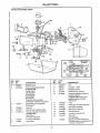
Care of Your Opener
Limit and force adjustment
controls
The remote control
3-FUNCTION
Open this end
Limit Controls
Force Controls
A_ustmen= L_bel
(Lor_led on the left side pBneI)
(Located on the right side pane_)
_ent
_..,
The lithium batteries should
produce power for up to
5 years. To replace batteries,
hc_s_ny
use the visor clip or screwdriver
blade to pry open the case as COMPAC_
Twistheref-_<:_O..x_
_
shown. (=Open" location is
to open
stamped on back of remote
control case 0 Insert batteries positive side down.
Label
Weather conditions may cause some minor
changes in door operation requiring some readjustments,
particularly
during the first year of
operation.
Replace cover as follows. 3-Function remote: Insert
the 3 tabs at the opposite end and snap shut.
Compact 3-Function remote: Snap shut along both
sides.
Pages 28 and 29 refer to the limit and force
adjustments. Only a screwdriver is required. Follow
the instructions carefully.
Dispose
of old batteries
properly.
Repeat the safety reverse test (page 30) after any
adjustment
of limits or force.
Maintenance
Schedule
Once a Month
Twice a Year
Manually operate door. If it is unbalanced or
binding, calI for professional garage door service.
Check chain tension. Disconnect trolley first.
Adjust if necessary (See page 11)o
Once a Year
Check to be sure door opens and closes fully.
Adjust limits and/or force if necessary.
(See pages 28 and 29_)
Oil door rollers, bearings and hinges. The opener
does not require additional fubdcation. Do not
grease the door tracks..
Repeat the safety reverse tesL Make any
necessary adjustments (See page 30).
31
ii
Operation
Activate
of Your Opener
the opener with any of the following:
• The Remote Control: Hold push button down until
the door starts to mover
- The Door Control: Hold push button down until
the door starts to move.
• The Outdoor
Accessories)
Weak or broken springs could allow an open
door to fall (either rapidly or unexpectedly),
resulting
in serious injury, death or property
damage.
If possible,
use the emergency
release rope and handle only when the door is
fully closed.
Key Switch or Keyless Entry: (See
When the opener is activated with the safety
reversing sensor installed and correctly aligned:
1. If open, the door will close. If closed, the door will
open.
2. If closing, the door will reverse.
T ,ley
3. If opening; the door will stop (allowing space for
entry and exit of pets and for fresh air).
4. If the door has been stepped in a partially open
position, it will close.
Trolley
._
5. If obstructed while closing, the door will reverse.
6. If obstructed while opening, the door will stop.
Emergency
Release Hat.He
7., The garage door will reverse in the closing cycle
when the invisible beam is broken. If fully open,
the door will not close when the beam is broken.
The sensor has no effect in the opening cycle.
(Pull Down)
Manual disconnect
position
If the sensor is not installed, or is not aligned
correctly, the door wont close from any remote
transmitter,. You can close the door with the Door
Control, the Outdoor Key Switch, or Key_ess Entry,
however, if you activate them until down travel is
complete° If you release them too soon, the door will
reverse.
To open the door
manually:
The door should be
fully closed ff possible.
Pull down on the red
emergency release
handle and lift the door
manually. To
reconnect the door to
the opener, press the
Door Control push
button.
prevents
the trolley
The lockout
feature from
__ey
reconnecting automatically,_
Pull the emergency handle
down and back (toward the
opener). The door can then
be raised and lowered
manually as often as
The opener lights will blink for 5 seconds when the
safety reversing sensor causes the door to reverse.
Trolley
will reconnect on the next
UP or Down operation_
"_
_k
necessary. To disengage
the Lockout Feature, pull
the emergency handle
straight down. The trolley
The Opener Lights will turn on under the following
conditions: When the opener is inilJaily plugged in;
when the power is interrupted; when the opener is
activated. They will turn off automatically after 4-1/2
minutes or provide constant light when the Light
feature on the Premium Control Console is activated.
SECURITY+ models: Lights will also tum on when
someone walks through the open garage door. Bulb
size is 75 watts maximum.
j
Emorg_r_y
R_easeHandle
(Pu_Do_ &eack
Towards
Opener)
Lockout
position
Operation
of the Door Controls
(see page 18)
(SECURITY+ models: See additional programming features, next page.)
Press the lighted push button to open or close the
door.
Premium Console (conto):
Lock Feature-The Lock feature is designed to
prevent operation of the door from remote controls.
However, the door will open and close from the Door
Control, the Outdoor Key Switch and the Keyless Entry
Accessories°
Press again to reverse the door during the closing
cycle or to stop the door while it's opening.
Premium Console:
Light Feature - Press the large round Ught button. If
the opener lights are off, they will turn on. If the
opener lights are on, (even in the 4-1/2 minute
automatic cycle) they will turn off.
To Activate: Press and hold the small round Lock
button for 2 seconds. The push button light will flash
as long as the Lock feature is on.
To tum off: Press and hold the Lock button again
for 2 seconds.The push button light wilt stop
flashing. The Lock feature will also turn off whenever
the "SRT" button on the opener panel is activated..
But if you use the Light button to turn the lights on
and then activate the opener, the lights will turn off
after 4-1/2 minutes,
The Ught button will not control the opener lights
when the door is in motion.
32
Receiver
and Remote
Control
Programming
Tocomp__;_ FCC¢u_s. adiu_rn_¢_
or n_ot,s
_(t_'or v-anstn;'_ are _
repla_
receiver changes with each use, randomly accessing
over 100 bilIion new codes.
garage door openers and/or
opener will operate with:
THE.RE ARE NO OTH_'R USER
SERVICF_ABLE
1
A moving garage door could injure or kill
someone under it. Activate the opener only
when you can see the door cleady, it is free of
obstructions, and ls properly adjusted.
• several SECURITY,tl, remote controls (with blue
push buttons) utilizing up to 8 functions.
• one SECURITY,I139.53684).
or_i_roc_iver-_
tt_ecode se_jn9 orl
Children operating or playing with a gara!
door opener can injure themselves or others.
The garage door could close and cause serious
injury or death. Do not allow children to operate
the door push button(s) or remote con_ol(s).
The 3-function remote control can also activate
Your SECURITY+
for d"_._g
PARTS,,
Your garage door opener receiver and remote control
have been pro-set at the factory. The door will open
when you press the LARGE remote control push
button,, The code between the remote control and the
additional SECURITY+
light controls.
the bakery
_
Keyless Entry System (Model
Follow the instructions below to program your opener
to match any additional remotes you may purchase.
See Accessories on page 38.
Figure
1
Selea a remoze _
pu_
button to operate opener
To Add A Remote Control
ff you have a Premium
Control Console:
1 With the door dosed, press and hold a remote
control push button, See Figure 1.
SECURITY-I3-Function
Remote Control
2. Press and hold the Ught button on the door
control
3, Press and hold the door control push button.
Figure
2
SECURITY+
Garage Door Opener
4_After the opener light flashes, release all buttons.
Test by pressing the remote push button.
ff you do not have a Premium
Control Console;
1oPress and holdthe selected remote control push
button. See Figure 1.
*SRT" (learn)
Bu_to¢_
2.Then press and release the SRT (learn) button on
the back panel of the opener, Figure 2oThe
indicator light on the panel will begin to blink and
the opener light will flash once_
To Control the Opener Ught (Premium
Consoles)
With SECURITY+ remote controls, a push bt_on can
be programmed to operate the opener light without
opening the door.
1. With the door closed, press and hold the remote
button that you want to control the light.
3. Release the remote push button.
Test by pressing the remote push button.
To Erase All Remote
rndk:;atm" RIGHT
Lkjht
PANEL
Control Codes
Press and hold the SRT button on the opener panel
until the indicator light turns off (about 6 seconds). All
remote control codes are now erased. Then follow
the stops above to re-program each remote control.
2. Press and hold the Ught button on the door
control,
3o Press and hold the Lock button on the door control.
4, After the opener light flashes, release all buttons.
Test by pressing the remote push button. The opener
light should turn on or off but the door should not move.
33
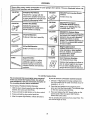
Having
Situation
Probable
Cause
a Problem?
and Solution
.......J
"The opener doesn't
operate from either
the Door Control or
the remote controb
1. Does the opener have electric power?. Plug a lamp intothe oLr_et. If it doesn't light,
check the fuse box or the circuit breaker._ (Some outlets are controlled by a door switch.)
2o Have you disabled all door locks? Review installa*Jon instructionwarnings on Page 11.
3. Is there a build-up of ice or snow under the door?. The door may be frozen to the
ground. Remove any restriction.
4. The garage door spring may be broken. Have it replaced.
5- Repeated operation may have tripped the overload protector in the motor. Wait
15 mintxtes. Try again.
Opener operates
from the remote
control, but not from
the Door Control:
t_ Is the Door Control tit? If not, remove the bell wire from the opener terminal screws.
Short the red and white terminals by touching both terminals at the same time with a
piece of wire. If the opener runs, check for a faulty wire connection at the Door
Control, a short under the staples, or a broken wire.
2. Are the wiring connections correct? Review Step 6, page 18.
illllll.i
The door operates
from the Door
Control, but not from
the remote control:
i
,i,illlll
iiiiiiiiiiiiii i ,i
i
t. Is any door push button flashing? If your model has the Lock feature, make sure the
lock is Off.
2, Your opener needs to re-learn a remote control code. Refer to Instructions on the
opener panel.
3. Program the receiver to match the remote control code.
4. Repeat the receiver programming
iiii i i
procedure with all remote controls.
ii
The remote control
has short range:
!. Change the location of the remote control in your car.
2. Check to be sure the antenna on the side or back panel of opener extends fully
downward.
3. Some installations may have shorter range due to a metal door, foil backed
insulation, or metal garage siding. (Antenna Extender Kit 41A3504)
IHI
Opener noise is
disturbing in living
quarters of home:
The garage door
opens and closes
by itseih
IIIlllll
I II I
I
If operational noise is a problem because of proximity of the opener to the living
quarters, the Vibration Isolator Kit 4tA3263 can be installed° This kit was designed to
minimize vibration to the house and is easy to install.
1. Be sure that all remote control push buttons are off.
2. Remove the bell wire from the Door Control terminals and operate from the remote
control only. If this solves the problem, the Door Control is faulty (replace), or there is
an intermittent short on the wire between the Door Control and the opener.
3. Clear memory and reprogram all remote controls.
iiiii
ii iiii
I.HI
IIIIllll
I.
I
The door doesn't
1, Is something obstructing the door?. Remove the obstruction or repair the door.
open completely:
2. If the door has been working properly but now doesn't open all the way, increase the
up force. See page 29.
3. If door opens at least 5 feet, the travel limits may need to be increased. One turn
equals 2 inches of travel. See page 28.
Repeat the safety reverse test after the adjustment
,1111
ill
The door stops but
doesn't close
completely:
i
,llllllll,lll
,ll
ill
is complete.
i
Review the travel limits adjustment procedures on page 28.
Repeat the safety reverse test after any adjustment
force or down limit.
34
of door arm length, close
*t
i
,_
Having
Situation
Probable
i
i
l llll
lllll
The door opens but
won't close:
i
i ill
i i i
a Problem?
Cause
i
(continued)
& Solution
Illll
I I
N,ll
1. If the opener lights blink, check the safety reversing sensor. See page 23,
2. If the opener lights do not blink and it is a new installation, check the down force.
See Adjustment Step 2, page 29. For an existing installation, see below.
Repeat the safety reverse test after the adjustment
The door revet'ses for
no apparent reason
and opener lights
don _tblink:
is complete.
1. Is something obstructing the door?. Pull the red emergency release handle. Operate
the door manually. If it is unbalanced or binding, ball for professional garage door
service.
2. Clear any ice or snow from the garage floor area where the door closes.
3. Review the force adjustment procedures on page 29.
4o If door reverses in the fully closed position, decrease the travel limits (page 28).
Repeat safety reverse test after adjustments to force or travel limits. The need
for occasional adjustment of the force and limit seffdngs is normal. Weather
conditions in particular can affect door travel.
The door reverses for
no apparent reason
and opener lights
blink for 5 seconds
after reversing:
Check the safety reversing sensor° Remove any obstruction or align the receiving eye.
See page 23.
The opener lights:
...
don't turn on:
Replace the light bulbs (75 watts maximum). Use a standard neck garage door opener
bulb if regular bulb bums out.
...
don't turn off:
ls the Light feature on? Turn it off.
The opener strains or
maximum force is
needed to operate
door:
The door may be out of balance or the springs are broken. Close the door and use the
emergency release to disconnect the trolley. Open and close the door manually, A propedy
balanced door will stay in any point of travel while being supported entirely by its springs. If it
does not, disconnect the opener and call a professional garage door serviceman° Do not
increase the force to operate the opener.
The opener motor
hums briefly, then
won't work:
1. The garage door springs are broken. See above.
2. If the problem occurs on the first operation of the opener, door may be locked. Disable
the door lock. If the chain was removed and reinstalled, the motor may be out of phase.
Remove the chain; cycle the motor to the down position, Observe the drive sprocket.
When it tums in a clockwise direction and stops in the down position, reinstall the chain.
Repeat the safety reverse test after the adjustment
The opener won't
operate due to
power failure:
is complete.
1, Use the emergency release to disconnect the trolley. The door can be opened and dosed
manually. When the power is restored, press the Door Control push button and trolley will
automatically reconnect (unlesstrolley is in lockout pos_ono) See page 32_
2. The Emergency Key Retease accessory (for use on garages with no service door)
disconnects the trolley from outside the garage in case of power failure.
The chain
or sags:
droops
It is normal for the chain to droop slightly in the closed door position. Use the
emergency release to disconnect the trolley_ If the chain retums to normal height when
the trolley is disengaged and the door reverses on a one-inch board, no adjustments
are needed (see page t 1),.
35
Repair Parts
Rail Assembly
Parts
3
KEY
NO.
1
2
3
4
5
6
7
4
4
PART
NO.
DESCRIPTION
Master link kit
1A995
41A3489
1B3117
Complete trolley assembly
T-rail - center section
T-rail - end section
183Bl10
41B2616
41A3473
83A4
Cable pulley bracket assembly
Chain and cable
Rait grease
NOT SHOWN
Rail assembly hardware kit
(includes hardware illustrated on
page 7).
41A3534
=
Installation
Parts
4
NO.
t
2
NO.
DESCRIPTION
41A4884
41A5032
Premium controlconsote
3-function remote centre! housing
(no circuit board)
3V 2016 Lithium battery (2 required)
Visor clip
Keg/less entry keypad cover
Keyless entry battery cover
12Volt battery
Emergency rope & handle assembly
Header bracket wtctev_s pin & fastener
2*conductor be!l wire - white & white/red
Curved door arm section
Door bracket w/clevis pin & fastener
Safety sensor kit (receMng and sending eyes)
with 3' 2-conductor bell wire attached
3
4
5
6
7
8
9
10
11
t2
13
10A19
298134
31 D431
31B430
'10A2
41 A2828
41A4353
217A238
178B35
41 A5047
41A4373A
14
15
12B483
12B484
16
12B485
17
12B350
18
178B34
41 A3475-4
41A41t6
114A2122
"C" Wrap Bracket
Square Hote Bracket
S!otted Bracket
Hanging brackets
Straight door arm section
NOT SHOWN
Installation hardware bag (includes hardware
illustrated on page 7),
Safety sensor hardware
Owner's manual
36
13
--14
15
=
, 1,1
Repair
Parts
=nn=
, )p(:ner Assembly
Parts
I
19
18
13
17
KEY
NO.
1
2
3
PART
NO.
DESCRIPTION
31 D380
Sprocket cover
41 C4220A
41A2817
4
5
41 B4245
41 C4253
6
41 A5021-2
7
8
4tA4351
175B88
15
14
KEY
NO.
Gear and sprocket assembly
Complete with:
Spring washer
Thrust washer
Retaining ring
Bearing plate
Roll pins (2)
Drive gear and worm gear
Helical gear w/retainer and grease
Drive/worm gear kit w/grease
Roll pins (2)
Line cord
Wire harness assembly w/plug
Receiver logic board assembly
Complete with:
Logic board
End paneI w/ail labels
End panel w/all labels
PART
NO.
DESCRIPTION
9
108D48-2
Lens
10
11
12
30B363
t 2A373
41A3150
Capacitor-
13
41 D3058
Universal replacement motor &
bracket assembly
Complete with: Motor, worm,
bracket, bearing assembly,
RPM sensor
t4
15
41 D0328-7
41A2818
Cover
16
17
41 [33452
41 C4398A
18
19
41 A2826
41A2822A
Shaft bearing kit
20
41A4352
End panel
NOT SHOWN
Opener assembly hardware kit
(includes screws not designated by
a number in illustration),
41 A2825
Light socket
1/2HP
Capacitor bracket
Terminal block w/screws
Helical gear & retainer w/grease
Limit switch assembly
RPM sensor assembly
Interrupter cup assembty
i= ,u,,
37
ACCESS,.
..............................
,,,,,,,,, ,,,,,
..........................
Sears offers many useful accessories for your garage door opener, They are Illustrated below _ tth
Sears model numbers and descriptions.
iii
iii
i
,111
139.53702
,,,,,
,,,,,,
,,,,,,,11111111
J
iu ,, ,,
,,,,,,,,,,,,,,
139.53681
Emergency Key Release:
SECURITY÷
Control:
Required for a garage with NO
access door. Enables homeowner
to open garage door manually from
outside by disengaging trolley.
SECU RITY÷ Compact
3-Function Remote Control:
Outdoor Key Switch:
Operates the garage door
automatically from outside when
remote control is not handy,
i1,11ii
H
139.53704
With loop for attaching key ring.
(Available April, t 997)
139.53684
SECURITY÷ Keyless Entry:
Enables homeowner to operate garage
door opener from outside by entering a
password. Also can add a temporary
password for visitorsor service
persons. This temporary password can
be limited to a programmablenumber
of hours or entries.
139.53686
Plug-In Light Control:
Enables homeowner to turn on a
lamp, television or other appliance
iiii1,1,,i,1,1
ii
8 Foot Rai! Extension
To allow an 8 foot door to open fully.
iiii ii
139.53705
i,i, ii
i
i,iii i i
10 Foot Rail Extension:
To allow a 10 foot door to open fully.
@
_1
,, ,,,
53885
Retool --
Includes visor clip.
139.53680
139.53703
3:Funciion
139.53709
Support Brackets:
,
_
the home with a remote.
from car, bedside, or anywhere in
(Available
Apdl, 1997)
.................................................
Door Clearance Brackets:
(FOr Sectional Doors Only)
For finished ceilings or where
additional support is required,
based on garage construction.
Includes brackets and fastening
hardware.
Replaces top brackets and rollers on
door to reduce height of door travel.
For use when installing opener in
garage with low headroom clearance.
To Add the Keyless Entry
We recommend that you program your password
before you install the Keyless Entry. You will not
need assistance, and you can test the reception at
the mounting location before installation.
ff you do not have a Premium Control'Console:
If you have a Premium Control Console:
2.. Press the four buttons for the password, then
press and hold the Enter button. The indicator light
on the door opener panel will blink.,
1.. Choose a 4-digit password using numbers from
0 to 9 (a number can be used more than once, for
example, 4, 0, 4, 1).
1. With the door closed, press the four digit password
desired, then press and hold Enter.
3, Press and release the SRT (learn) button on the
opener panel. After the opener light flashes,
release the Enter button°
2. Press and hold the light button on the door control.
3o Press and hold the door control push bar.
4. After the opener light flashes, release all buttons.
Test by pressing the password, then press Enter° The
door should begin to move.
38
Index
Access Door/Outside
Electrical
Key Release Accessory ................................................................................................
4, 5
Safety Warnings .................................................................................................................................... 2, 20, 31
Garage Door
Testing for balance, binding and sticking .............................................. _.........................................................................
3, 28, 31
Determining high point of travel:
Sectional door ....................................................................................................................................................
12
One-piece door ..................................................................................................................................................
Disabling existing locks .....................................................................................................................................
Door clearance brackets (for garages with low headroom) .............................................................................
Force controls
13
3, 11
12, 38
Adjustment procedures ......................................................................................................................................
4, 29
Problems that might require force adjustments .............................................................................................
34, 35
Safety warnings ............................................................................................................................................
.29, 31
Door hardware .....................................................................................................................
3, 9, 11, 12, 18, 31, 32
Maintenance instnJction label ..........................................................................................................................
11, 28
Reinforcement requirements .................................................................................................................................
4, 24
Removing of all ropes .........................................................................................................................................
3, "11
Possible door damage ....................................................................................................................................
16, 24
Travel limits
Adjustment procedures ........................................................................................................................................
Problems that might require limit adjustments ..................................................................................................
Safety warnings ...............................................................................................................................................
28
34, 35
28, 31
Manual (Emergency) Release Rope & Handle
Lockout feature ..........................................................................................................................................................
32
Manual disconnect ......................................................................................................................................................
32
Safety warnings .....................................................................................................................................
11, 19, 31, 32
Opener Terminals
Door control connections ...........................................................................................................................................................
18
Safety reversing sensor connections ..........................................................................................................................
23
Operational Noise
Sprocket noise .......................................................................................................................................................
11
Vibration noise (isolator kit) ............................................................................................................................................. 34
Receiver and Remote Control
Programming the receiver .................................................................................................................................................. 33
Erasing all codes ....................................................................................................................................................................33
Activating other openers ...........................................................................................................................................
33
Safety waming .........................................................................................................................................................................
33
Problems with remote control operation ..................................................................................................................
34
Safety Reverse Test Procedure ..............................................................................................................................
30
Testing required ......................................................................................................................................
11,30, 34, 35
Safety reverse system problems
Securing header bracket to wall ..........................................................................................................................................
12
Adjusting travel limits ...................................................................................................................................................... 28
Applying excessive force on the door ......................................................................................................................
29
Buckling or uneven floor ..................................................................................................................................................4, 5
Safety Warnings .............................................................. 2, 3, 9, 11, 12, 16, 18, 19, 20, 21,24, 28, 29, 30, 31, 32, 33
User Instruction
Label for garage wall .................................................................................................................................
I 1, 18
39
For professional
installation
Cal! 24 hours a day, 7 days a week
t -800-865..6500
For the repair or replacement parts you need
Call 7 am - 7 pm, 7 days a week
t -800-366-PART
(1-800-366-7278)
For in-home major brand repair service
Call 24 hours a day, 7 days a week
t -800-4-RIEPAIR
(1-800-473-7247)
For the location of a Sears Repair Service Center in your area
0
db
Call 24 hours a day, 7 days a week
1-800-488-1222
For information on purchasing a Sears Maintenance Agreement
or to inquire about an existing Agreement
A
Ca!! 9 am - 5 pro, Monday-Saturday
t -800-827=6655
The model number label is located under the light lens on the
front end panel of your opener. When requesting service or
ordering parts, always give the following information:
o Product Type
° Model Number
- Part Number
. Part Description
Ame#ca's Repair Specialists
SEARS WARRANTY
FULL 90-DAY WARRANTY
ON GARAGE
DOOR OPENER
For 90 days from the date of purchase, Seats will repair this Garage Door Opener, free of charge, if defective in mateda] or
workmanship_
LIMITED WARRANTY
From the 91st day unt{! one year from the date of purch_e, Seam will furnish replacement parts for any defective parts, free of charge
You pay for labor.
LIMITED WARRANTY ON MOTOR
t/2HP MOTOR: After I year and through 5 yeats, if the motor on this Garage Door Opener is defective,
motor, free of charge.. You pay for labor.
LIMITATION ON L1ABILFrY
Seam will furnish a replacement
SEARS WILL NOT BE LIABLE FOR LOSS OR DAMAGE TO PROPERTY OR ANY INCIDENTAL OR CONSEQUENTIAL
LOSS OR
EXPENSE FROM PROPERTY DAMAGE DUE DIRECTLY OR INDIRECTLY FROM THE USE OF THIS PRODUCT. Some states do
not allow the exclusion
or _imitation of incident_ ar consequential damages, so the above limita_on or e:(clusion may not apply to you.
This warranty does not cover light butbs or repair parts necessa_ because of operator abuse or negligence, including the failure to
install, adjust and operate this garage door opener according to instruct{ons contained in the owner's manual.
WARRANTY SERVICE |S AVAILABLE BY SIMPLY CONTACTING THE NEAREST SEARs CENTERiOEPARTMENT
iN THE UNITED
STATES.
.This warranty
appfies onty white this product is in use in the United States.
This warranty gives you specific legal rights, and you may atso have other rights which vary from state to state_
Sears, Roebuck
114A2122
and Co.., DepL 817WA,
Hoffman
©1996, All Rights Reserved
Estates, IL 60179
Printed in Mexico