1
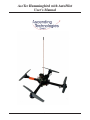
AscTec Hummingbird with AutoPilot
User’s Manual
-1-
AscTec Hummingbird with AutoPilot User’s Manual
Inhaltsverzeichnis
1 Introduction
1.1 System overview . . . . . . . . . . . . . . .
1.1.1 X-CSM . . . . . . . . . . . . . . . .
1.1.2 AscTec Hummingbird PowerBoard .
1.1.3 AscTec AutoPilot . . . . . . . . . . .
1.1.4 AscTec 3D-MAG . . . . . . . . . . .
1.1.5 GPS unit . . . . . . . . . . . . . . .
1.1.6 Motors . . . . . . . . . . . . . . . .
1.1.7 X-BLDC brushless motor controllers
1.1.8 Propellers . . . . . . . . . . . . . . .
1.2 Transmitter . . . . . . . . . . . . . . . . . .
.
.
.
.
.
.
.
.
.
.
4
4
4
5
5
6
6
6
6
7
7
2 Things to do before the first flight
2.1 Mounting the propellers . . . . . . . . . . . . . . . . . . . . . . . . . . . . . . . . . . . . .
2.2 Preparing your own battery . . . . . . . . . . . . . . . . . . . . . . . . . . . . . . . . . . .
2.3 Teach-in of your transmitter . . . . . . . . . . . . . . . . . . . . . . . . . . . . . . . . . .
8
8
8
9
.
.
.
.
.
.
.
.
.
.
.
.
.
.
.
.
.
.
.
.
.
.
.
.
.
.
.
.
.
.
.
.
.
.
.
.
.
.
.
.
.
.
.
.
.
.
.
.
.
.
3 Operating the AscTec Hummingbird with AutoPilot
3.1 Status LEDs . . . . . . . . . . . . . . . . . . . . . . .
3.2 Acoustic signals given by the AscTec AutoPilot . . . .
3.3 Important things to keep in mind . . . . . . . . . . . .
3.4 Learning to fly . . . . . . . . . . . . . . . . . . . . . .
3.4.1 General hints . . . . . . . . . . . . . . . . . .
3.4.2 First flights . . . . . . . . . . . . . . . . . . .
3.4.3 Enabling height control . . . . . . . . . . . . .
3.4.4 Flying in GPS mode . . . . . . . . . . . . . .
4 On-Board serial interface
4.1 Physical interface . . . .
4.2 Data protocol . . . . . .
4.2.1 Data output . . .
4.2.2 Command input .
4.3 System calibration . . .
.
.
.
.
.
.
.
.
.
.
.
.
.
.
.
.
.
.
.
.
.
.
.
.
.
.
.
.
.
.
.
.
.
.
.
.
.
.
.
.
.
.
.
.
.
.
.
.
.
.
.
.
.
.
.
.
.
.
.
.
.
.
.
.
.
.
.
.
.
.
.
.
.
.
.
.
.
.
.
.
.
.
.
.
.
.
.
.
.
.
.
.
.
.
.
.
.
.
.
.
.
.
.
.
.
.
.
.
.
.
.
.
.
.
.
.
.
.
.
.
.
.
.
.
.
.
.
.
.
.
.
.
.
.
.
.
.
.
.
.
.
.
.
.
.
.
.
.
.
.
.
.
.
.
.
.
.
.
.
.
.
.
.
.
.
.
.
.
.
.
.
.
.
.
.
.
.
.
.
.
.
.
.
.
.
.
.
.
.
.
.
.
.
.
.
.
.
.
.
.
.
.
.
.
.
.
.
.
.
.
.
.
.
.
.
.
.
.
.
.
.
.
.
.
.
.
.
.
.
.
.
.
.
.
.
.
.
.
.
.
.
.
.
.
.
.
.
.
.
.
.
.
.
.
.
.
.
.
.
.
.
.
.
.
.
.
.
.
.
.
.
.
.
.
.
.
.
.
.
.
.
.
.
.
.
.
.
.
.
.
.
.
.
.
.
.
.
.
.
.
.
.
.
.
.
.
.
.
.
.
.
.
.
.
.
.
.
.
.
.
.
.
.
.
.
.
.
.
.
.
.
.
.
.
.
.
.
.
.
.
.
.
.
.
.
.
.
.
.
.
.
.
.
.
.
.
.
.
.
.
.
.
.
.
.
.
.
.
.
.
.
.
.
.
.
.
.
.
.
.
.
.
.
.
.
.
.
.
.
.
.
.
.
.
.
.
.
.
.
.
.
.
.
.
.
.
.
.
.
.
.
.
.
.
.
.
.
.
.
.
.
.
.
.
.
.
.
.
.
.
.
.
.
.
.
.
.
.
.
.
.
.
.
.
.
.
.
.
.
.
.
.
.
.
.
.
.
.
.
.
.
.
.
.
.
.
.
.
.
.
.
.
.
.
.
.
.
.
.
.
.
.
.
.
.
.
.
.
.
.
.
.
.
.
.
.
.
.
.
.
.
.
.
.
.
.
.
.
.
.
.
.
.
.
.
.
.
.
.
.
.
.
.
.
.
11
11
11
11
12
12
12
13
13
.
.
.
.
.
15
15
15
15
17
17
5 Contact Information
18
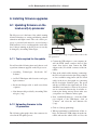
A Installing firmware upgrades
A.1 Updating firmware on the LowLevel(LL)-processor . . . . . . . . . . . . . . . . . . . . . .
A.1.1 Tools required for the update . . . . . . . . . . . . . . . . . . . . . . . . . . . . . .
A.1.2 Uploading firmware to the LL-processor . . . . . . . . . . . . . . . . . . . . . . . .
19
19
19
19
Ascending Technologies GmbH
-2-
www.asctec.de
AscTec Hummingbird with AutoPilot User’s Manual
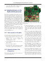
A.2 Updating firmware on the HighLevel(HL)-processor . . . . . . . . . . . . . . . . . . . . . .
A.2.1 Tools required for the update . . . . . . . . . . . . . . . . . . . . . . . . . . . . . .
A.2.2 Uploading firmware to the HL-processor . . . . . . . . . . . . . . . . . . . . . . .
20
20
20
B Troubleshooting
B.1 Slight tilt in pitch/roll with the pitch/roll stick in neutral position . . . . . . . . . . . . . . .
B.2 Considerable tilt in pitch or roll . . . . . . . . . . . . . . . . . . . . . . . . . . . . . . . . .
B.3 Bad reception during flight . . . . . . . . . . . . . . . . . . . . . . . . . . . . . . . . . . .
22
22
22
23
C Data structures to be polled for information
24
Ascending Technologies GmbH
-3-
www.asctec.de
AscTec Hummingbird with AutoPilot User’s Manual
1 Introduction
Thank you for purchasing a Vertical Take-Off and
Landing (VTOL) air vehicle equipped with the AscTec AutoPilot. Please read this manual carefully before you start to work with your new device.
It is strictly forbidden to use them in any military environment or to retail them to any military or military
related organization. Using any of our components for
larger scale flying objects is also not allowed.
WARNING!
SUBJECT TO CHANGE WITHOUT NOTICE.
The AscTec AutoPilot is a powerful tool, enabling
the vehicle to hover autonomously in one place and
thus making it very easy to control. However, it is
important that you understand how to control the
vehicle in situations where GPS receiption is bad or
not available. As a pilot you are required to always
fly within visual range.
A motorized model aircraft like the AscTec Hummingbird is not a toy! It should only be flown by
adults. Improper assembly or operating can lead
to severe injuries and / or damages. Trouble with
your remote control due to interferences can occur
any time without prior notice. Sometimes, a model
aircraft can suddenly become uncontrollable due to a
failure of any component, including mechanical parts
and electronics. In this case, the model can rapidly
move towards any direction. Make sure you always
keep a safe distance to people, animals, obstacles
or things of any kind, traffic roads, etc.. There are
country-specific laws regulating the operation of
model aircrafts for non-commercial and also for
commercial applications that definitely have to be
obeyed. Furthermore, we strongly recommend to
effect a liability insurance for such an aircraft in
your application. Ascending Technologies does not
have any influence on, nor can they monitor the
correct final assembly and proper operation of your
aircraft. Always be aware of the dangers mentioned
above and act accordingly. There is no liability of the
manufacturer nor the retailer at all, as far as legally
approved.
1.1 System overview
In this section you find some information about the
subsystems used in the AscTec Hummingbird w/ AutoPilot.
1.1.1 X-CSM
The X-CSM is the mechanical frame of the AscTec
Hummingbird. The booms, which are made of a rigid
carbon fiber-balsa wood sandwich material, can be
replaced individually. The central unit of the frame
called the ”X-CSM Core” is made of light weight
laser-cut magnesium parts. Being built out of these
state-of-the-art materials the X-CSM is a very robust
high-tech basis for your quadrotor aircraft.
Our products are designed for the civil market only.
Ascending Technologies GmbH
-4-
www.asctec.de
AscTec Hummingbird with AutoPilot User’s Manual
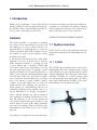
1.1.2 AscTec Hummingbird
PowerBoard
Motor I2 C
+ –
–
+
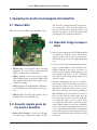
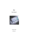
The PowerBoard is used to distribute power and
communication lines to all motor controllers. It
comprises a switching power regulator to generate a
stable 6V supply for the AscTec AutoPilot board, a
high-power MosFET to switch the motor current ON
and OFF and a 5V regulator to supply any custom
payloads like e.g. a 2.4 GHz wireless video camera.
There are also some soldering pads where extension
boards can be connected to an SPI or I2C bus of
the AscTec AutoPilot’s high level processor. The
ON-OFF switch is designed active low, so if for
some reason the mechanical switch breaks or looses
connection the vehicle is switched ON by default.
PWR
switch
connector
5V
–
+
12V
Motor I2 C
bottom side
SDA
SCL
HL interface
SSEL
MOSI
SCK
MISO
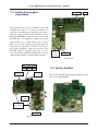
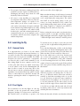
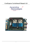
1.1.3 AscTec AutoPilot
AutoPilot
connectors
Motor I2 C
The AscTec AutoPilot is the sensing and flight control
unit of your Hummingbird.
–
+
–
+ –
+
Power
connector
X-BLDC
power supply
–
+
–
+
Motor I2 C
top side
Ascending Technologies GmbH
-5-
www.asctec.de
AscTec Hummingbird with AutoPilot User’s Manual
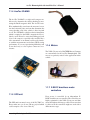
1.1.4 AscTec 3D-MAG
The AscTec 3D-MAG is a triple-axial compass module used to determine the vehicles heading by measuring the Earth’s magnetic field. The AscTec AutoPilot mathmatically transforms the measured vector
into the horizontal plane and can thus determine the
correct heading even if the vehicle is tilted in pitch
or roll. The 3D-MAG is a high resolution instrument,
which is required as the Earth’s magnetic field is relatively week. Please be aware that adding payloads
close to the compass, especially radio modules like a
video transmitter or an antenna could severly interfere with the measurements and reduce GPS hovering
performance. If you are experiencing difficulties and
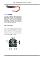
1.1.6 Motors
do not find a way to solve it please contact us for assistance.
The X-BL-52s motors by HACKER Motors Germany
are custom-built for the AscTec Hummingbird. The
motors are perfectly suited for the application in this
vehicle.
1.1.7 X-BLDC brushless motor
controllers
1.1.5 GPS unit
Every motor is controlled by an independent XBLDC brushless motor controller. The controllers are
highly optimized for the X-BL-52s motors and thus
The GPS unit is mounted on top of the X-CSM Core. ensure the highest efficiency possible. Please note that
Please make sure you do not add any payload which for this reason the controllers might not work with a
different motor type.
could comprise a free view of the sky.
Ascending Technologies GmbH
-6-
www.asctec.de
AscTec Hummingbird with AutoPilot User’s Manual
1.1.8 Propellers
The AscTec Hummingbird’s standard propellers are
made of flexible PP-plastics. Their low mass and high
flexibility make the vehicle one of the safest R/C quadrotor there is. This is especially convenient when
conduction indoor experiments. However, please make sure you always keep a safe distance to people and
follow the safety instructions above.
1.2 Transmitter
Any 6 or more channels R/C transmitter can be used
to operate the AscTec Hummingbird w/ AutoPilot.
Even if it is controlled autonomously using e.g. a PCSoftware and a wireless data link, the transmitter is
required as a backup. As a safety measure the AscTec
AutoPilot is by default not able to launch without a
valid signal from the R/C transmitter.
Ascending Technologies GmbH
-7-
www.asctec.de
AscTec Hummingbird with AutoPilot User’s Manual
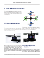
2 Things to do before the first flight
The AscTec Hummingbird w/ AutoPilot comes completely assembled and tested. You only have to do the
following steps to make it work in combination with
your equipment.
2.1 Mounting the propellers
To improve the durability of the propellers during a
The propellers can be slid over the axles and be faste- crash you can optionally add a cable tie (e.g. 2.5 x
ned using a plastic nut. Do not fasten the nut too tight, 100 mm) as seen in the following picture.
as this would bend the propellers.
Please note that there are two types of propellers: One 2.2 Preparing your own
pair of propellers is spinning clockwise, the other pair
battery
is spinning counterclockwise. The propellers spinning clockwise must be mounted to the front and
the rear motor, whereas the counterclockwise rotating You need a 3s (three cells, 11.1V) Lithium Polymer
propellers must be mounted to the left and to the right (LiPo) Battery to operate the AscTec Hummingbird.
motor.
We recommend capacities between 1500 and 2100
Ascending Technologies GmbH
-8-
www.asctec.de
AscTec Hummingbird with AutoPilot User’s Manual
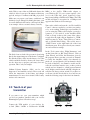
mAh. With a state-of-the-art 2100 mAh battery the MHz) or the AscTec USB-to-cable adapter to
vehicle is able to hover up to 20 minutes without any your Windows PC. If your system requires a dripayload, and up to 12 minutes with 200 g of payload. ver for the USB chip, please download it here:
http://www.ftdichip.com/Drivers/VCP.htm. The USB
Make sure you prepare your battery such that it can
module will then be recognized as a COMport and
definitely not get damaged by hitting the frame, even
appear in the Windows device manager.
in a crash. Otherwise the battery could explode! Here
is an example of how to mount a battery correctly:
Turn on the vehicle and start the AscTec AutoPilot
”
Control“ software e-mailed to you after your purchase by an Ascending Technologies representative. If
you are using the USB-to-cable adapter you need to
connect it to LL serial 0“ on the AutoPilot PCB.
”
Click on Setup“ in the top left corner of the softwa”
re and select the right comport. Baudrate is 57600“
”
and Flowcontrol is None“. Then Click on Connect“
”
”
and on Enable Data Polling“. The red dot next to
”
UART Comm“ on the right hand side of the form
”
should turn green. If not, please check your connections and connection settings.
The black foam on both sides prevents it from being
hurt by the magnesium parts of the frame. Configured
like this the battery slides into the battery slot of the
vehicle and holds inside by friction. Of course, there
are also other ways to prepare your battery for a safe
operation. This is only an example.
Lithium Polymer Batteries (LiPo) can be very
dangerous if not handled correctly. Please read and
follow the instructions of the battery and charger
manufacturers! Do never short circuit a LiPo battery
and use safe connectors!
In the Tools“-menu select Flight Parameters“ and
”
”
on that form click on R/C Setup Wizard“. Click on
”
Start Wizard“ and follow the instructions given by
”
the program. Please note that you need six channels
to control the AutoPilot vehicle: four channels for
pitch, roll, yaw and throttle (all four channels should
be sticks on the R/C), one channel to enable and disable the serial data interface (two or three position
switch) and one channel to switch between manual
mode, height controlled mode and GPS + height controlled mode (three position switch). If you have never flown a model aircraft before we would recommend the following setup for the first four channels:
2.3 Teach-in of your
transmitter
If you want to use your own transmitter, which
you did not purchase bundled with your AscTec
Hummingbird, please follow these steps:
Connect the USB module of your wireless data link (XBee 2.4GHz or Radiotronix 868/900
Ascending Technologies GmbH
-9-
www.asctec.de
AscTec Hummingbird with AutoPilot User’s Manual
Once the R/C setup wizard says Calibration data col”
lected“ go back to the Flight Parameters“ form and
”
click on Transmit Values“. The form should briefly
”
turn yellow (while transmitting data) and then back to
grey if the data was transmitted correctly. If it doesn’t
turn grey again click Transmit Values“ again. After
”
that, click Write to FLASH“ to permanently store
”
the new set of parameters in the vehicle’s FLASHmemory.
Now, go back to the main form. In the field RC Da”
ta“ you should now see the values coming from your
R/C. With all sticks and switches centered the values
should be around 2048. Please verify if your stick inputs are according to the following table:
Command
Value
Pitch forward
4095
Pitch backward
0
Roll left
4095
Roll right
0
Yaw left
4095
Yaw right
0
Full throttle
4095
Minimum throttle 0
The correct function of the two switches can be verified by looking at the Flight Mode“ field on the
”
bottom of the form.
Ascending Technologies GmbH
- 10 -
www.asctec.de
AscTec Hummingbird with AutoPilot User’s Manual
3 Operating the AscTec Hummingbird with AutoPilot
3.1 Status LEDs
The interval is getting faster the lower the battery voltage gets. At 9 volts (critical limit!) the
tone stays steady. Please land the vehicle soon
after the tone appears, as the LiPo battery might
get damaged if it is discharged under 9V.
There are four status LEDs on the AutoPilot board.
1
2
3.3 Important things to keep in
mind
• Directly after turning the AscTec Hummingbird
w/ AutoPilot on both the motors and the piezo
speaker produce a short beep. It is perfectly normal that the propellers move slightly during that
tone.
3
4
• LED 1 (red) is on as long the sensors are being
initialized. Do not move the vehicle until this
LED is off and LED 2 starts flashing.
• LED 2 (green) is the main-processor status
LED. During normal operation this LED is blinking rapidly, indicating that the flight control
software is running.
• LED 3 (green) is the GPS hardware OK indicator. It is blinking at 2.5 Hz during normal operation.
• LED 4 (red) is the GPS status indicator. If it is
flashing, there is no valid GPS lock.
3.2 Acoustic signals given by
the AscTec AutoPilot
• Battery low warning: A loud tone will appear if the battery voltage drops under 9.8 Volts.
Ascending Technologies GmbH
- 11 -
• Do not move the AscTec Hummingbird after turning it on until LED 2 of the AutoPilot starts
blinking. Otherwise, the sensors can not be calibrated correctly and the vehicle might go crazy
after turning on the motors. If you accidentally
moved the system during startup simply turn it
off and on again.
• After the startup phase the motors are still turned off and secured. To turn them on you have to
move the yaw stick to the very left or to the very
right while your throttle stick is in zero position.
The motors will then start and keep running at
their minimum speed. To turn the motors off you
have to do the same procedure again: Move the
yaw stick to the very left or to the very right while your throttle stick is in zero position. There
is no flight maneuver where one would use this
control input and thus you will not accidentally
turn off your motors during flight. For safety reasons you should turn off the motors immediately
if one of the propellers touches the ground or any
other obstacle and hence the vehicle is not able
to take off.
www.asctec.de
AscTec Hummingbird with AutoPilot User’s Manual
• Do not ignore the battery warning giving by the until you are able to fly in tight spots.
AutoPilot (acoustic signal as described above).
Discharging the battery deeper than 9V could
Make sure that the battery is fully charged, connected
drastically reduce its lifetime.
and mounted correctly. Switch on the vehicle and be
• All sensors on the AutoPilot are compensated really careful during the startup phase. The vehicle
for temperature drift effects. However, if the am- must NOT be moved during startup as the gyro
bient temperature changes too rapidly, for in- sensors are being initialized! If the vehicle was
stance when you fly from a warm room to a moved during startup simply turn it off and on again.
cold outdoor environment, the angles estimated The startup sequence is completed once LED 2 is
by the datafusion algorithms might not be totally blinking. Now the vehicle is ready to fly.
correct. As a consequence, your vehicle would
be tilted a bit, even with a neutral pitch and roll
command. In this case we recommend to wait a Before starting the motors make sure that the threefew minutes, until all sensors have adopted to the position switch on your R/C controlling channel 6
(GPS and height control OFF – height control enabled
ambient temperature.
– GPS and height control enabled) is in OFF position.
3.4 Learning to fly
3.4.1 General hints
It is important that you learn to fly the vehicle
manually before using the autonomous functions, i.e.
you need to be able to fly without height control and
position control by air pressure and GPS. Good GPS
receiption can never be guaranteed - consequently
you must be able to take control manually at any
time during flight. In most countries even by law
a safety pilot must always be within visual range
to an air vehicle as the AscTec Hummingbird and
must be able to control it at any time. Due to the
onboard sensors and the sophisticated flight control
algorithms even in manual mode the vehicle is much
easier to control than most other R/C aircrafts and
therefore operating the vehicle is comparatively easy
to learn.
To start the motors you have to move the yaw stick
to the very left or right whilst holding throttle in zero
position.
If it is the first flight after a while or the first flight
at all hold your AscTec Hummingbird down to the
ground. You can grab the center part of the frame, but
make sure that you don’t touch any of the rotors.
In case the vehicle tries to tilt in any direction and
one or more of the propellers are going crazy: Turn
the motors off immediately (same stick command
as used for turning the motors on)! Then, switch the
vehicle off and on again and try again. If the problem
still occurs please read the troubleshooting section of
this manual.
Angle stabilization in pitch and roll is active even
when the propellers are running idle. Use this feature as you hold the vehicle from below and tilt it
carefully to check that everything works. As you tilt
it to one direction you must feel some counterforce
from the motors if everything is o.k.. You can also try
to steer the pitch and roll axis and see that you can
directly steer the angles. Please check if the vehicle
3.4.2 First flights
is leveled in your hand with the pitch and roll stick
in neutral position. If not, correct any undesired tilt
We recommend to do the first flights on some big with the pitch and roll trimmers.
grassland, as the soft ground will soften possible
emergency landings. If you have never controlled an
R/C aircraft before you will have to practice a bit Before the first take-off make sure that the red mark
Ascending Technologies GmbH
- 12 -
www.asctec.de
AscTec Hummingbird with AutoPilot User’s Manual
(front!) is pointing away from you, as in this case
the vehicle will move forward if you push your pitch
stick forward. Now, give a little throttle and the
vehicle should lift off. In manual mode, the throttle
stick on your remote directly controls the average
thrust of the rotors, the pitch/roll stick sets a desired
angle in these axes. Try hovering in a height of about
1m and concentrate on the red marking which is
the front of your vehicle. It is perfectly normal that
the vehicle drifts slowly in all directions without
GPS control enabled. Try to compensate for these
movements using the pitch/roll stick and try to hold
the height of about 1m by gently moving the throttle
stick up and down. After a while you will be able to
keep the vehicle hovering in one place. After a few
battery charges you will able to fly in any room, and
with some more practice you can even fly in small
spaces and land on tables etc.. Good luck!
3.4.3 Enabling height control
Once you feel comfortable controlling the vehicle
manually put the GPS/height control switch in center
position (”height control enabled”). Now, the vehicle
tries to hold its current height as long as the throttle stick is centered. Moving the stick up and down
commands an ascending/descending rate. It is recommended to use the height control mode only outdoors. Please make sure you fly high enough above
the ground (at least at eye level) when using the height
control mode as turbulences or gusts might cause rapid changes in air pressure which might make the vehicle move up and down a bit without any command.
As long as the vehicle is standing on the ground make
sure you hold the throttle stick down (not in neutral
position!) to keep the motors idle. When taking off
from the ground in height control mode please make
sure you push the throttle stick all the way up until
the vehicle is at a safe height (at least eye level).
3.4.4 Flying in GPS mode
Ascending Technologies GmbH
GPS operation in general
Flying the vehicle in GPS mode is very easy as
long as GPS receiption is good. However, as perfect
GPS receiption can never be guaranteed, the pilot
must be able to control the vehicle manually in
every situation. GPS mode is enabled by putting
the GPS/height control switch on the R/C in GPS
position. If the vehicle appears to become instable in
GPS mode or seems to not react to user commands
you need to push the GPS/height control switch to
manual mode immediately to take over control. As
I pilot you are responsible to control your vehicle in
a safe way, even if an electronic assistance like GPS
control fails.
Please note that in GPS mode height control is always
enabled, too.
It is perfectly normal that the vehicle is not absolutely stationary when hovering in GPS mode without
any control command. The GPS position measurements are supported by the inertial sensors on-board,
which makes the position estimate much more reliable than what can be expected from a standard GPS
receiver. However, the inertial sensors can compensate for short-term effects like a jump in the GPS position when a new satellite comes in view, but they
cannot compensate for long-term drift or position errors.
How to determine weather the GPS fix is
valid
In all firmware versions LED 4 ( GPS status indica”
tor“) is flashing to warn the pilot, if there is no valid
GPS fix. It stays off if the GPS signal is OK. There is a
special firmware for the HighLevel-processor giving
an acoustic warning if the GPS signal is bad. This
firmware is usually not installed on the AscTec Hummingbird with AutoPilot, as this vehicle is often used
for indoor research. Please note that the GPS controller is automatically disabled if there is no valid GPS
fix. In this case, the vehicle reacts as if the GPS/height
control switch was in center position (height control
- 13 -
www.asctec.de
AscTec Hummingbird with AutoPilot User’s Manual
height, at least at eye level. For the landing you also
need to make sure that there is enough free space surrounding the vehicle, as especially close to the ground
Hand control in GPS mode
the GPS position might drift quite a bit due to signal
reflections. For starting and landing in tight spots it is
When in GPS mode, the yaw and throttle/height recommended to launch and land the vehicle in macontrol stick on the R/C still has the same function nual mode and switch to GPS mode once it is in a safe
as in height control mode. The pitch and roll stick height.
still controls the same axes, but the vehicle behaves
different as in manual mode. When flying in GPS
Waypoint navigation
mode the vehicle always is in a speed controlled
state. This means, no matter how far you push the
pitch/roll stick, the vehicle will not travel faster than The vehicle only accepts waypoint commands by a
defined in its control parameters. In windy conditions PC or an external control computer mounted to it (e.g.
it will travel at almost the same speed going up-wind a GumStix processor board) when the switch on the
and going down-wind. The moment you push the R/C is in GPS position. Any stick input on the R/C
stick from center to any direction the vehicle will will override a waypoint command. For safety reachange its tilt in that direction rapidly to accelerate sons it is absolutely necessary that there is always a
until it has reached the desired speed. Then it will safety pilot standing by with the R/C in his hands to
tilt back to an angle at which it travels at the desired take over control if something is not working as exspeed in the current wind conditions. The further you pected.
push the stick, the faster the vehicle goes. If you put
the stick back to center the vehicle will stop at its
current position. With the standard parameter set the
vehicle will not move faster than about 2 meters per
second in hand controlled GPS mode.
In GPS mode it is possible and also recommended
to control one function of the vehicle at a time,
e.g. first fly to a desired height, then move to a
desired position, then turn the heading to a desired
orientation.
enabled), even with the switch in GPS mode.
Starting and landing in GPS mode
It is possible to launch the vehicle directly in GPS
mode, but it has to be done with care as the vehicle
might move a bit into any direction during the launch.
If you do want to launch directly in GPS mode make sure that there is enough free space surrounding
the vehicle and that persons are standing at least 10m
away from it. After turning on the motors make sure
you hold the throttle stick down (not in neutral position!) to keep the motors idle. When you are ready,
you should start immediately by pushing the throttle
stick all the way up until the vehicle hovers in a safe
Ascending Technologies GmbH
- 14 -
www.asctec.de
AscTec Hummingbird with AutoPilot User’s Manual
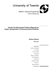
4 On-Board serial interface
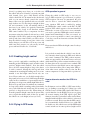
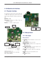
4.1 Physical interface
To communicate with the vehicle using the XBee link
or USB cable adapter please connect to the correct
virtual comport using the following connection settings:
LL
I/O
Baudrate: 57600
Flow control: ”Hardware” for XBee, ”None” for
USB cable adapter
HL
I/O
Databits: 8, 1 startbit, 1 stopbit, no parity
LL Serial 0
Compass
connector
4
HL Bootloader
Jumper
Buzzer
connector
ADC
LL
4.2 Data protocol
3
4.2.1 Data output
1
HL
5
2
Data structures
LL STATUS: Status information of the low level
processor
IMU RAWDATA: Sensor raw-values
LL Serial 1/
R/C receiver
HL Serial 1/
GPS
HL JTAG
HL Serial 0
1:
2:
pressure sensor
acceleration sensor
3: yaw gyro
4: nick gyro
5: roll gyro
LL/HL Serial 0 (Pin 1..6):
TXD, RXD, CTS (Input), +3.3V, +6V, GND
Max. current: 300 mA!
Ascending Technologies GmbH
IMU CALCDATA: Calibrated sensor outputs and
data fusion results
CTRL INTERNALOUT: Controller internals and
outputs before output mapping
CTRL OUT: Controller outputs after output mapping
RC Data: Data received by the R/C receiver
GPS Data: GPS data
- 15 -
www.asctec.de
AscTec Hummingbird with AutoPilot User’s Manual
GPS Data Advanced: GPS data + position and
speed estimates after data fusion
data ˆ= (crc & 0xff);
data ˆ= data << 4;
The data structures in detail are shown in Appendix
return ((((unsigned short) data << C.
→8) | ((crc>>8)&0xff)) ˆ (unsigned
There is a unique packet descriptor/ID for every struc→ char) (data >> 4) ˆ ((unsigned ture. Here is a list of all packet descriptors used in the
→short) data << 3));
system:
}
//packet descriptors
#define PD_IMURAWDATA
#define PD_LLSTATUS
#define PD_IMUCALCDATA
#define PD_HLSTATUS
#define PD_DEBUGDATA
0x01
0x02
0x03
0x04
0x05
#define
#define
#define
#define
#define
#define
#define
#define
PD_CTRLOUT
PD_FLIGHTPARAMS
PD_CTRLCOMMANDS
PD_CTRLINTERNAL
PD_RCDATA
PD_CTRLSTATUS
PD_CTRLINPUT
PD_CTRLFALCON
0x11
0x12
0x13
0x14
0x15
0x16
0x17
0x18
#define
#define
#define
#define
#define
#define
#define
#define
#define
#define
PD_WAYPOINT
PD_CURRENTWAY
PD_NMEADATA
PD_GPSDATA
PD_SINGLEWAYPOINT
PD_GOTOCOMMAND
PD_LAUNCHCOMMAND
PD_LANDCOMMAND
PD_HOMECOMMAND
PD_GPSDATAADVANCED
0x20
0x21
0x22
0x23
0x24
0x25
0x26
0x27
0x28
0x29
unsigned short crc16(void* data, →unsigned short cnt)
{
unsigned short crc=0xff;
unsigned char * ptr=(unsigned char
→*) data;
int i;
for (i=0;i<cnt;i++)
{
crc=crc_update(crc,*ptr);
ptr++;
}
return crc;
}
example use:
unsigned short checksum=crc16(&
→IMU_CalcData, sizeof(IMU_CalcData))
→;
Requesting (polling) data structures
The user can select the desired data structures by sending the following string to the vehicle.
>*>p[unsigned short packets]
The following bits set in ”packets” request a data
startstring:
>*>
structure:
length of structure:
unsigned short
0x0001 LL Status
packet descriptor:
unsigned char
0x0002 IMU RawData
the actual data structure: ”length of structure” bytes 0x0004 IMU CalcData
crc16:
unsigned short
0x0008 RC Data
stopstring:
<#<
0x0010 CTRL Out
0x0080 GPS Data
0x0100 current way
CRC16 algorithm
0x0200 GPS Data Advanced
0x0800 CAM Data
All structures are sent as follows:
unsigned short crc_update (unsigned
→short crc, unsigned char data)
{
Ascending Technologies GmbH
Please note that you can set as many bits at a time
as required in your application. The vehicle will then
- 16 -
www.asctec.de
AscTec Hummingbird with AutoPilot User’s Manual
transmit all structures that were requested and wait
for the next poll. Due to the limited bandwidth of almost all kinds of radio modems it is recommended
that you only request (poll) the packets you need, e.g.
if you are only interested in the computed pitch and
roll angles you should only poll IMU CalcData and
none of the other packets.
These bits can be used to only →enable one axis at a time and
→ thus to control the other →axes manually. This usually →helps a lot to set up and →finetune controllers for each
→ axis seperately. */
short chksum;
};
struct CTRL_INPUT CTRL_Input;
4.2.2 Command input
The chksum is calculated as follows right before the
structure is sent:
Operation
CTRL_Input.chksum = CTRL_Input.pitch
The serial command interface must be enabled by
→+ CTRL_Input.roll + CTRL_Input.yaw the switch on channel 5 of your 35 MHz or 72 MHz
→+ CTRL_Input.thrust + CTRL_Input.
R/C. Please use the AscTec AutoPilot PC-Software
→ctrl + 0xAAAA;
to see which position of the switch enables the serial
interface.
The data should be sent to the vehicle with a minimum rate of 10 Hz over the XBee link as follows:
1. startstring: >*>di
During operation through the serial command interface the R/C has to stay on all the time to enable a
safety pilot to take over if the autonomous control is
not working as desired. Please make sure that there
is always a safety pilot ready to immediately disable
the serial interface and to take manual control of the
vehicle.
2. directly followed by the above data structure,
e.g.
UART_send( &CTRL_Input, sizeof(
→CTRL_Input));
If data is sent with significantly less than 10 Hz or
if the transmission stops completely the system will
switch back to manual control over the R/C.
Data protocol
The current control dataset must be available in the
following format:
struct CTRL_INPUT { //serial commands
→ (= Scientific Interface)
short pitch; //Pitch input: →-2047..+2047 (0=neutral)
short roll;
//Roll input: →-2047..+2047
(0=neutral)
short yaw;
//(=R/C Stick input) →-2047..+2047 (0=neutral)
short thrust; //Collective: 0..4095
→ = 0..100%
short ctrl;
/*control byte:
bit 0: pitch control enabled
bit 1: roll control enabled
bit 2: yaw control enabled
bit 3: thrust control enabled
Ascending Technologies GmbH
4.3 System calibration
The AscTec Hummingbird with AutoPilot comes
fully calibrated. Calibration usually lasts for the
whole lifetime of the vehicle. If you feel something
is wrong with the calibration of your system please
contact Ascending Technologies for assistance.
- 17 -
www.asctec.de
AscTec Hummingbird with AutoPilot User’s Manual
5 Contact Information
Ascending Technologies GmbH
Graspergerstr. 8
82131 Stockdorf
GERMANY
Phone: +49 89 89949847
E-Mail: [email protected]
Web: www.asctec.de
CEOs:
Michael Achtelik, Klaus-Michael Doth
Dipl.-Ing. Daniel Gurdan, Dipl.-Ing. Jan Stumpf
Handelsregister M¨unchen: HRB 166748
Ust.-ID: DE254728199
Ascending Technologies GmbH
- 18 -
www.asctec.de
AscTec Hummingbird with AutoPilot User’s Manual
A Installing firmware upgrades
A.1 Updating firmware on the
LowLevel(LL)-processor
The LL-processor is the heart of the vehicle running
all critical functions as sensing and filtering, attitude
estimation and flight control. The code on this processor is protected and cannot be accessed using a
JTAG interface nor be read through the serial interface. Software running on the LL-processor can only
be changed by Ascending Technologies.
LL bootloader
jumper
Please follow these steps to upload new code to the
LL-processor:
A.1.1 Tools required for the update
You will need the following items and software tools
to perform a firmware upgrade on the LL-processor:
• Ascending
Software
Technologies
Bootloader
PC-
• AscTec USB-adapter with four wires and a grey
6-pin connector
• Bootloader Jumper cable or small screw driver
or pincers
• New firmware file provided by Ascending Technologies (*.atp)
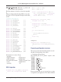
• Connect the USB-adapter to your computer (install the FTDI virtual comport driver if this
wasn’t done before), then connect the USBadapter to the LL-serial 0“ connector of the Au”
toPilot.
• Turn on the vehicle while shorting (connecting)
the LL-bootloader activation pins using a jumper
or if not available using pincers (the two black
cables in the above photograph are connecting
the LL-bootloader activation pins). The green
and the red LED on the right hand side of the
AutoPilot board must be solid now. If not, there
was no connection between the bootloader activation pins during start-up. Please make sure
your pincers are conductive and try again.
• Start AutoPilotUpdater.exe“, select the COM”
port assigned to the USB-adapter, click on
Connect“ and select the new firmware file
”
(*.atp).
A.1.2 Uploading firmware to the
LL-processor
The following photograph shows the connectors involved in the LL update process.
Ascending Technologies GmbH
LL serial 0
- 19 -
• Click on Start programming“.
”
• When programming is finished turn off the vehicle, disconnect the USB-adapter from the AutoPilot and turn the vehicle back on. Now, the
www.asctec.de
AscTec Hummingbird with AutoPilot User’s Manual
green status LED should be flashing again, signalizing that the new code is running.
A.2 Updating firmware on the
HighLevel(HL)-processor
In its factory programmed state the HL-processor is
only used to monitor the battery voltage and to parse
and forward GPS data. Plenty of computing power is
left for user applications. Using the software development kit (SDK) provided by Ascending Technologies
users can write their own code and upload it to the
HL-processor. Please note that the firmware versions
of HL and LL-processor have to be compatible. Therefore, if you purchased your vehicle a while ago and Please follow these steps to upload new code to the
you want to upload new firmware generated with the HL-processor:
newest SDK code base please contact us for an upda• Connect the USB-adapter to your computer (inted LL-processor firmware.
stall the FTDI virtual comport driver if this
The HL-processor is not code-protected and consewasn’t done before), then connect the USBquently read- and writeable by the user. This can
adapter to the HL-serial 0“ connector of the Aube done using NXPs official tools to program an
”
toPilot.
LPC2146 ARM processor.
A.2.1 Tools required for the update
You will need the following items and software tools
to perform a firmware upgrade on the LL-processor:
• LPC2146 flash tool, as for instance Flas”
hMagic“
(free software, available at
www.flashmagictool.com)
• AscTec USB-adapter with four wires and a grey
6-pin connector
• Bootloader Jumper or pincers
• New firmware file, either provided by Ascending
Technologies or generated by the SDK(*.hex)
• Start Flash Magic“, select the COM-port assi”
gned to the USB-adapter and set the other parameters to Baudrate 115200, Device LPC2146,
Interface None(ISP), Oscillator 14.7456 MHz.
• Check Erase all Flash and Code Rd Prot“, select
”
the new firmware file (*.hex), uncheck all options under Step 4 and click on start programming.
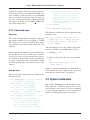
A.2.2 Uploading firmware to the
HL-processor
The following photograph shows the connectors involved in the update process.
Ascending Technologies GmbH
• Turn on the vehicle while holding the HLbootloader jumper pads connected using pincers
(or a jumper if installed). The two LEDs signalizing the GPS state (next to the jumper pads) will
stay off and the battery warning buzzer will make a loud noise. If not, there was no connection
between the pads during start-up. Please make
sure your pincers are conductive and try again.
You may put some tape on the front of the buzzer to cancel the noise - it won’t vanish before
the update is done and the vehicle is reset.
- 20 -
• When programming is finished turn off the vehicle, disconnect the USB-adapter from the AutoPilot and turn the vehicle back on. Now, the
www.asctec.de
AscTec Hummingbird with AutoPilot User’s Manual
GPS status LEDs should be flashing again, signalizing that the new code is running.
Ascending Technologies GmbH
- 21 -
www.asctec.de
AscTec Hummingbird with AutoPilot User’s Manual
B Troubleshooting
This chapter holds solutions to problems which might
occur during the operation of your AscTec Hummingbird w/AutoPilot.
B.1 Slight tilt in pitch/roll with
the pitch/roll stick in
neutral position
Due to unavoidable measurement errors or the
unbalance of mechanical parts it is perfectly normal
that the AscTec Hummingbird w/ Autopilot is not
always 100% levelled during flight with the control
sticks in neutral position. A slight tilt can easily be
compensated by the trimmers on your remote control.
B.2 Considerable tilt in pitch
or roll
There are some situations where the measured angle
can considerably differ from the real angle, which results in big tilt-angles in pitch and/or roll while the
pitch/roll stick on your remote is centered. This can
have the following reasons:
• Shaking during initialization: It is very important that the vehicle is not moved at all during the
initialization phase. Calibration errors caused by
shaking during startup can affect the system performance in many ways. If the vehicle tilts more
and more after starting the motors it is very likely that it was moved during the initialization.
In this case, please turn it off and on again and
make sure that it is not moved until the AutoPilot displays the Ready to flyLED-pattern (LED 1
(red) off, LED 2 (green) blinking).
Ascending Technologies GmbH
- 22 -
• Teach-in of your transmitter was not correct: To
check if your transmitter was taught-in correctly,
please refer to section ??.
• Rapid change of the ambient temperature or operation under extreme temperature conditions:
Temperature compensation is applied to all sensors of the AscTec AutoPilot. We have not encountered any problems with temperature yet.
However, in theory it is possible that you might
get drift effects and therefore unwanted tilt in
pitch or roll if you for instance fly directly from
a warm room into a very cold outdoor environment. If this happens, please turn the vehicle off,
let the electronics adopt to the ambient temperature and try again.
• Extremely fast maneuvers: Fast maneuvers,
which result in high accelerations interacting
with your aircraft, can cause faulty measurements. If you fly several circles in a row in high
speeds it can happen, that the measured angle
differs several degrees from the real angle. If this
is the case, you simply have to fly gently or hover for a few seconds until the unwanted tilt is
gone, as the data fusion system usually is able to
recover very quick.
• Flying on a circular path in always the same direction for a longer period of time: The centripetal force affecting your vehicle when flying on
a circular path prevents the sensors from measuring the earth’s gravity vector. In this case, the
other sensors on-board the vehicle are used by
the on-board software to estimate the real tilt of
the vehicle. This works for quite a long time, but
at some point the errors may become significant.
Therefore it is recommended that after flying a
full circle in one direction the pilot should fly
straight for a couple of seconds or a circular path
in the other direction. If you experience such a
problem simply keep the vehicle hovering until
www.asctec.de
AscTec Hummingbird with AutoPilot User’s Manual
the unwanted tilt is gone.
• Faulty calibration of the accelerometers: If none
of the reasons above apply the problem might
be due to a bad system calibration. In this case
please contact AscTec for assitance.
B.3 Bad reception during flight
If the vehicle does not react while it is airborne,
please check if someone else uses the same channel.
Make sure your TX battery is fully charged and that
the antenna is fully extended.
Ascending Technologies GmbH
- 23 -
www.asctec.de
AscTec Hummingbird with AutoPilot User’s Manual
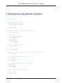
C Data structures to be polled for information
struct LL_STATUS
{
//battery voltages in mV
short battery_voltage_1;
short battery_voltage_2;
//don’t care
short status;
//Controller cycles per second (should be ˜1000)
short cpu_load;
//don’t care
char compass_enabled;
char chksum_error;
char flying;
char motors_on;
short flightMode;
//Time motors are turning
short up_time;
};
struct IMU_RAWDATA
{
//pressure sensor 24-bit value, not scaled but bias free
int pressure;
//16-bit gyro readings; 32768 = 2.5V
short gyro_x;
short gyro_y;
short gyro_z;
//10-bit magnetic field sensor readings
short mag_x;
short mag_y;
short mag_z;
//16-bit accelerometer readings
short acc_x;
short acc_y;
short acc_z;
Ascending Technologies GmbH
- 24 -
www.asctec.de
AscTec Hummingbird with AutoPilot User’s Manual
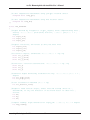
//16-bit temperature measurement using yaw-gyro internal sensor
unsigned short temp_gyro;
//16-bit temperature measurement using ADC internal sensor
unsigned int temp_ADC;
};
struct IMU_CALCDATA
{
//angles derived by integration of gyro_outputs, drift compensated by data
→fusion; -90000..+90000 pitch(nick) and roll, 0..360000 yaw; 1000 = 1 →degree
int angle_nick;
int angle_roll;
int angle_yaw;
//angular velocities, raw values [16 bit] but bias free
int angvel_nick;
int angvel_roll;
int angvel_yaw;
//acc-sensor outputs, calibrated: -10000..+10000 = -1g..+1g
short acc_x_calib;
short acc_y_calib;
short acc_z_calib;
//horizontal / vertical accelerations: -10000..+10000 = -1g..+1g
short acc_x;
short acc_y;
short acc_z;
//reference angles derived by accelerations only: -90000..+90000; 1000 = 1
→degree
int acc_angle_nick;
int acc_angle_roll;
//total acceleration measured (10000 = 1g)
int acc_absolute_value;
//magnetic field sensors output, offset free and scaled; units not →determined, as only the direction of the field vector is taken into
→account
int Hx;
int Hy;
int Hz;
//compass reading: angle reference for angle_yaw: 0..360000; 1000 = 1 degree
int mag_heading;
Ascending Technologies GmbH
- 25 -
www.asctec.de
AscTec Hummingbird with AutoPilot User’s Manual
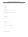
//pseudo speed measurements: integrated accelerations, pulled towards zero;
→units unknown; used for short-term position stabilization
int speed_x;
int speed_y;
int speed_z;
//height in mm (after data fusion)
int height;
//diff. height in mm/s (after data fusion)
int dheight;
//diff. height measured by the pressure sensor [mm/s]
int dheight_reference;
//height measured by the pressure sensor [mm]
int height_reference;
};
struct GPS_DATA
{
//latitude/longitude in deg * 10ˆ7
int latitude;
int longitude;
//GPS height in mm
int height;
//speed in x (E/W) and y(N/S) in mm/s
int speed_x;
int speed_y;
//GPS heading in deg * 1000
int heading;
//accuracy
unsigned
unsigned
unsigned
estimates in mm and mm/s
int horizontal_accuracy;
int vertical_accuracy;
int speed_accuracy;
//number of satellite vehicles used in NAV solution
unsigned int numSV;
// GPS status information; 0x03 = valid GPS fix
int status;
};
struct GPS_DATA_ADVANCED
{
//latitude/longitude in deg * 10ˆ7
Ascending Technologies GmbH
- 26 -
www.asctec.de
AscTec Hummingbird with AutoPilot User’s Manual
int latitude;
int longitude;
//GPS height in mm
int height;
//speed in x (E/W) and y(N/S) in mm/s
int speed_x;
int speed_y;
//GPS heading in deg * 1000
int heading;
//accuracy
unsigned
unsigned
unsigned
estimates in mm and mm/s
int horizontal_accuracy;
int vertical_accuracy;
int speed_accuracy;
//number of satellite vehicles used in NAV solution
unsigned int numSV;
//GPS status information; 0x03 = valid GPS fix
int status;
//coordinates of current origin in deg * 10ˆ7
int latitude_best_estimate;
int longitude_best_estimate;
//velocities in X (E/W) and Y (N/S) after data fusion
int speed_x_best_estimate;
int speed_y_best_estimate;
};
struct RC_DATA
{
//channels as read from R/C receiver
unsigned short channels_in[8];
//channels bias free, remapped and scaled to 0..4095
unsigned short channels_out[8];
//Indicator for valid R/C receiption
unsigned char lock;
};
struct CONTROLLER_OUTPUT
{
//attitude controller outputs; 0..200 = -100 ..+100%
int nick;
int roll;
Ascending Technologies GmbH
- 27 -
www.asctec.de
AscTec Hummingbird with AutoPilot User’s Manual
int yaw;
//current thrust (height controller output); 0..200 = 0..100%
int thrust;
};
Ascending Technologies GmbH
- 28 -
www.asctec.de