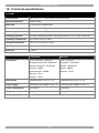
1
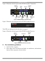
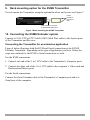
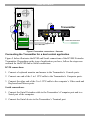
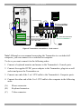
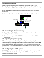
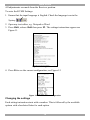
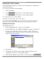
KVMS Extender
User Guide
w w w . m i n i c o m . c o m
International HQ
North American HQ
European HQ
Jerusalem, Israel
Linden, NJ, USA
Dübendorf, Switzerland
Tel: + 972 2 535 9666
[email protected]
Tel: + 1 908 486 2100
[email protected]
Tel: + 41 44 823 8000
[email protected]
Technical support - [email protected]
5UM30165 V1.2 01/07
KVMS EXTENDER
Table of Contents
1.
2.
3.
4.
5.
6.
7.
8.
9.
10.
11.
12.
13.
14.
15.
16.
17.
18.
19.
Welcome............................................................................................................................................... 2
What is the KVMS Extender? ............................................................................................................ 3
Features ............................................................................................................................................... 3
System components........................................................................................................................... 3
Compatibility ....................................................................................................................................... 3
KVMS Extender usage scenarios ..................................................................................................... 3
The KVMS Extender units.................................................................................................................. 4
Pre-installation guidelines................................................................................................................. 5
Rack mounting option for the KVMS Transmitter .......................................................................... 6
Connecting the KVMS Extender system ......................................................................................... 6
Connecting the Transmitter for an extension application.................................................................. 6
Connecting the Transmitter for a dual control application................................................................. 7
Connecting the Receiver .................................................................................................................... 9
Connecting to the power supply ...................................................................................................... 9
Adjusting the picture quality ............................................................................................................. 9
Configuring the KVMS system.......................................................................................................... 9
Changing the settings....................................................................................................................... 10
Operating the system ....................................................................................................................... 15
Upgrading the firmware ................................................................................................................... 15
The KVMS Extender Update software............................................................................................. 16
Setting the Com port......................................................................................................................... 16
Verifying the version numbers.......................................................................................................... 17
Updating the firmware ...................................................................................................................... 17
Safety.................................................................................................................................................. 18
Tips ..................................................................................................................................................... 18
Technical specifications .................................................................................................................. 19
User guide feedback......................................................................................................................... 20
1
USER GUIDE
1. Welcome
Thank you for buying the KVMS Extender system. This system is produced by
Minicom Advanced Systems Limited.
This document provides installation and operation instructions for Minicom’s
KVMS Extender.
Technical precautions
This equipment generates radio frequency energy and if not installed in accordance
with the manufacturer’s instructions, may cause radio frequency interference.
This equipment complies with Part 15, Subpart J of the FCC rules for a Class A
computing device. This equipment also complies with the Class A limits for radio
noise emission from digital apparatus set out in the Radio Interference Regulation
of the Canadian Department of Communications. These above rules are designed to
provide reasonable protection against such interference when operating the
equipment in a commercial environment. If operation of this equipment in a
residential area causes radio frequency interference, the user, and not Minicom
Advanced Systems Limited, will be responsible.
Changes or modifications made to this equipment not expressly approved by
Minicom Advanced Systems Limited could void the user’s authority to operate the
equipment.
Minicom Advanced Systems Limited assumes no responsibility for any errors that
appear in this document. Information in this document is subject to change without
notice.
No part of this document may be reproduced or transmitted in any form or by any
means, electronic or mechanical, for any purpose, without the express written
permission of Minicom Advanced Systems Limited.
Trademarks
All trademarks and registered trademarks are the property of their respective
owners.
2
KVMS EXTENDER
2. What is the KVMS Extender?
The KVMS Extender gives KVM & Serial extension and control up to
300m/1000ft away. It provides superior video quality over long distances and is an
excellent solution for clean rooms, kiosks, museums, banks and any other places
that need to keep their computers in a secure or environmentally controlled
location.
3. Features
·
KVM and serial control over single CAT5 cable
·
High video resolution up to 1920X1440 @ 60Hz
·
Dual-user function allows control by local or remote user
·
Full RS-232 data communication up to 57,600 bps
·
Skew compensation for easy video tuning
·
Ideal for digital signage applications
4. System components
The KVMS Extender system consists of:
·
1 KVMS Extender Transmitter (p/n 1DT50002)
·
1 KVMS Extender Receiver (p/n 1DT50001)
·
1 (3 in 1) CPU cable (p/n 5CB10413)
·
Serial Extender cable (p/n 5CB40018)
·
RS232 Download cable (p/n 5CB40419)
·
2 power adapters (p/n 5PSA0013)
·
Marketing & Documentation CD
·
Optional rack mount set (p/n 5AC00288)
5. Compatibility
The KVMS Extender system supports all major operating systems.
6. KVMS Extender usage scenarios
The KVMS Extender can be used as:
·
An extender
·
A dual control unit
3
USER GUIDE
Figure 1 illustrates the KVMS Extender system as an extender, with the
Transmitter up to 300m/1,000ft away from the Receiver. Figure 2 illustrates a dual
control scenario, whereby either the local or extended user can access and control
the computer.
KVM
KVM
CAT5 cable 300m/1,000ft
MINICOM
Po wer
Serial
L ink Act ive Lo cke d
Serial
MINICOM
KVMS Ext ender
KVMS E xtender
Po wer
L ink Act ive Lo cked
Transmitter
Receiver
Receiver
Transmitter
Computer
Figure 1 KVMS Extender as an extender
KVM
Serial
KVM
KVM
CAT5 cable 300m/1,000ft
MINICOM
Serial
Po wer
L ink Ac tive Lo cke d
Serial
MINICOM
KVMS Extender
KVMS Extender
Power
Transmitter
Lin k Activ e L ock ed
Receiver
Receiver
Transmitter
Computer
Figure 2 KVMS Extender in a dual control scenario
7. The KVMS Extender units
Figure 3 illustrates the front panel of the KVMS Extender Transmitter.
MINICOM
KVMS Extender
Power
Transmitter
Link Active Locked
Figure 3 KVMS Extender Transmitter front
The table below explains the LEDs.
LED
Meaning
Power
Link
Active
Locked
Power indicator
System cable connected to Transmitter and Receiver
Steady: This unit currently has control. Blinking: The other currently has control.
The other unit has locked control preventing this unit from taking control
4
KVMS EXTENDER
Figure 4 illustrates the back panel of the KVMS Extender Transmitter.
RS232
Terminal
Video
card
www.minicom.com
TERMINAL
Monitor
COMPUTER
System
cable
CONSOLE
5VDC
COMPUTER
SYSTEM
Keyboard Keyboard
Serial port
Mouse
Mouse
port
port
Power
SERVICE
Serial
Download
cable
Figure 4 KVMS Extender Transmitter back
Figure 5 illustrates the front panel of the KVMS Extender Receiver.
MINICOM
KVMS Extender
Power
Receiver
Link Active Locked
Figure 5 KVMS Extender Receiver front
The LEDs are explained in the table above on page 4.
Figure 6 illustrates the back panel of the KVMS Extender Receiver.
RS232
Terminal
Keyboard
System
cable
5VDC
TERMINAL
Power
SYSTEM
Mouse
Monitor
Figure 6 KVMS Extender Receiver back
8. Pre-installation guidelines
·
Switch off the computer
·
Place cables away from fluorescent lights, air conditioners, and machines
that are likely to generate electrical noise
5
USER GUIDE
9. Rack mounting option for the KVMS Transmitter
To rack mount the Transmitter using the optional brackets and screws see Figure 7.
Insert
screws to
connect to
rack
MINICOM
KVMS Extender
Power
Link
Active Locked
Transmitter
Insert screws to connect
to Transmitter side panel
Figure 7 Rack mounting the KVMS Transmitter
10. Connecting the KVMS Extender system
Connect a CATx UTP or FTP 2x4x24 AWG Solid Wire cable to the System ports
of the Transmitter and Receiver.
Connecting the Transmitter for an extension application
Figure 8 below illustrates both the KVM and Serial connections to the KVMS
Extender Transmitter. Depending on the type of application you have, follow the
steps now outlined for the KVM or Serial connections or both.
For the KVM connections:
1. Connect one end of the 3 in 1 CPU cable to the Transmitter’s Computer ports.
2. Connect the other end of the 3 in 1 CPU cable to the computer’s Video card and
Keyboard and Mouse ports.
For the Serial connections:
Connect the Serial Extender cable to the Transmitter’s Computer port and to a
Serial port of the computer.
6
KVMS EXTENDER
KB
Mouse
100T
Parallel
Serial A
Transmitter
Serial B
www.minicom.com
Video
TERMINAL
COMPUTER
CONSOLE
5VDC
COMPUTER
SYSTEM
Serial Extender cable
SERVICE
CAT5 cable to Receiver
3 in 1 CPU cable
Figure 8 Transmitter connections – Extender
Connecting the Transmitter for a dual control application
Figure 9 below illustrates the KVM and Serial connections of the KVMS Extender
Transmitter. Depending on the type of application you have, follow the steps now
outlined for the KVM and/or Serial connections.
KVM connections:
1. Connect a keyboard monitor and mouse to the Transmitter’s Console ports.
2. Connect one end of the 3 in 1 CPU cable to the Transmitter’s Computer ports.
3. Connect the other end of the 3 in 1 CPU cable to the computer’s Video card and
Keyboard and Mouse ports.
Serial connections:
1. Connect the Serial Extender cable to the Transmitter’s Computer port and to a
Serial port of the computer.
2. Connect the Serial device to the Transmitter’s Terminal port.
7
USER GUIDE
P110
KB
SD
Mouse
To Serial device
100T
Parallel
Serial A
Transmitter
Serial B
www.minicom.com
Video
TERMINAL
COMPUTER
CONSOLE
5VDC
COMPUTER
SYSTEM
Serial Extender cable
SERVICE
CAT5 cable to Receiver
3 in 1 CPU cable
Figure 9 Transmitter connections – dual control
Note! Although we recommend connecting the Transmitter to a switched off
computer, you can connect it to a switched on computer.
To do so you must connect it in the following order:
1. Connect a keyboard monitor and mouse to the Transmitter’s Console ports.
2. Connect the supplied 5VDC power adapter to the Transmitter, plug into a wall
socket and power the Transmitter on.
3. Connect one end of the 3 in 1 CPU cable to the Transmitter’s Computer ports.
4. Connect the other end of the 3 in 1 CPU cable to the computer in the following
order:
(A)
Mouse connector.
(B)
Keyboard connector.
(C)
Video connector.
8
KVMS EXTENDER
Connecting the Receiver
Figure 10 below illustrates the KVM and Serial connections of the KVMS
Extender Receiver. Depending on the type of application you have, follow the steps
now outlined for the KVM and/or Serial connections.
KVM connections: Connect a keyboard monitor and mouse to the Receiver’s
KVM ports.
Serial connections: Connect the Serial device to the Receiver’s Terminal port
P110
SD
To Serial device
Receiver
5VDC
TERMINAL
SYSTEM
CAT5 cable to Transmitter
Figure 10 Receiver connections
11. Connecting to the power supply
1. Connect the supplied 5VDC power adapters to the Transmitter and Receiver
and plug into a wall socket.
2. Power on the computer. The KVMS Extender system transmits the KVM and
Serial signals.
12. Adjusting the picture quality
When necessary, you can adjust the picture quality temporarily using the
Adjustment hotkey; Shift, D. From the Receiver position press Shift, release Shift
then press D, the picture adjusts. There are 6 looped preset adjustments. Press the
hotkey until the picture quality is satisfactory. Once the Receiver is switched off
the adjustment is lost. Adjustments are only saved in the KVMS Settings mode, see
the section below.
13. Configuring the KVMS system
The KVMS system has a number of configuration options. For example, control,
timeout, DDC refresh and video tuning. Also for UNIX servers, you must
configure the keyboard setting.
9
USER GUIDE
All adjustments are made from the Receiver position.
To enter the KVMS Settings:
1. Ensure that the input language is English. Check the language icon in the
Systray
.
2. Open any text editor, e.g. Notepad or Word.
3. Press Shift, release Shift then press F2. The settings instructions appear see
Figure 11.
Figure 11 Settings instructions
4. Press F6 to see the current configuration, see Figure 12.
Figure 12 Default current configuration
Changing the settings
Each setting instruction starts with a number. This is followed by the available
options with a bracketed letter for each option.
10
KVMS EXTENDER
To change a setting:
1. Press the keyboard number to enter the setting.
2. Press the keyboard letter of the desired option.
3. Press Enter until a confirmation appears that the settings are saved. Once saved
you exit the option.
Or
Press q to exit the option without saving.
4. Press Esc to exit the KVMS settings.
Note 1: Video quality adjustments can also be done using a hotkey with 6 preset
adjustments as explained in the Video brightness and tuning section below.
Note 2: Settings 0-5, only apply to the dual control scenario.
0 Video
You can have the screen appear at both Transmitter and Receiver positions, or only
at the currently active position. Tip! For an extender application set the video
display to appear at both positions.
1. Press 0. Text appears showing that you are in the video display mode.
2. Press b to have both positions display the video, or press c to have only the
active station showing the video.
3. Press Enter twice to save and exit the option.
The rest of the settings are explained below. To change them follow the steps as
outlined at the beginning of this section.
1 Serial control
You can have serial control at either the Transmitter (local) or at the Receiver
(remote) or at whichever position takes control (active). Tip! For an extender
application set serial control to be at the remote position.
2 Lock
Lock disabled allows the currently non-controlling position to take control by the
method outlined below in 3 Take control.
When Lock is enabled, control can be locked at one position preventing the other
position from taking control.
Section 14 on page 15 explains how the system operates when Lock is disabled or
enabled.
11
USER GUIDE
3 Take control
When control is not locked at one position, the non-controlling position can gain
control after a period of inactivity (timeout) or by pressing the hotkey Shift, F10.
Choose the method for taking control from the other position, either by timeout
(default) or hotkey.
Tip! For an extender application set switching control to be by timeout.
Tip! For a dual control application when the video is set to display at the current
active position, set switching control to be by hotkey
4 Timeout
When using the timeout period for taking control, you can change the timeout
period by typing a 3 digit number. For example, for a 50 second period, type 050.
By default timeout is 2 seconds.
5 Hotkey
You can change the hotkey from Shift to Control or PrintScreen. Once changed,
for every reference in this guide to Shift use the new hotkey.
6 Keyboard
The system operates with DOS, Windows, Novell, Linux, UNIX, HP UNIX, QNX,
SGI, FreeBSD, BeOS, Open VMS.
By default the Keyboard mode is set to PC which is suitable for most operating
systems.
Listed below is the keyboard mode for particular UNIX systems:
·
U1 for HP UX
·
U2 for Alpha UNIX, SGI, Open VMS
·
U3 for IBM AIX
Set the Keyboard mode according to above list.
7 DDC refresh
Display Data Channel (DDC) is a VESA standard for exchanging information
between a monitor and a video adapter.
In extender mode where there is no monitor connected to the Transmitter, the
computer boots with the default resolution and refresh rate. This may not be
suitable for the Receiver monitor. Choose to input the Receiver (remote) monitor’s
DDC information into the Transmitter’s memory. On booting the computer will
emulate the Receiver monitor type.
12
KVMS EXTENDER
Update the DDC information if you replace the monitor.
For a dual control scenario, we recommend using similar monitors at both
locations. When the monitors are not similar, input the DDC information of the
lower resolution monitor.
8 Video brightness and tuning
Where the image quality is unsatisfactory you can adjust it in the following 2 ways:
·
Video Adjustment hotkey - 6 looped preset adjustments
·
Video Adjustment tuning – for fine tuning
Press 8 to enter the Video adjustment settings.
Video Adjustment hotkey
Adjust the video quality using the 6 looped preset adjustments. Press D until the
picture quality is satisfactory.
Once you have a satisfactory image, press Enter twice to save and exit the option.
Video Adjustment tuning
Where the image needs further tuning after using the video Adjustment hotkey, do
the following:
Open the test card located on our website www.minicom.com/support/skew.png or
www.minicom.com/support/skew.gif or, on the supplied CD. See Figure 13. This
image will help you get the best screen image. It can also help to correct skew.
Figure 13 Test card
13
USER GUIDE
Press a letter key according to the list below and press the right or left arrow key to
adjust the image.
·
·
·
·
·
Notes:
[l]uminance – image brightness
[e]qualization – image sharpness
[r]ed delay – explained below
[g]reen delay– explained below
[b]lue delay– explained below
(a)
When you press one of the above letters, all three keyboard LEDs blink
indicating that you are in adjustment mode.
(b)
While pressing the arrow keys, when you reach the adjustment limits the
keyboard LEDs stop blinking.
After making an adjustment, you can press another letter key from the above list to
make a different adjustment.
Once you have a satisfactory image, press Enter twice to save and exit the option.
Red, green, blue delay
When transmitting video over CAT5 cables a horizontal misalignment (skew)
between the red, green and blue components inevitably occurs. This is because the
different length of each pair causes the signals to reach the monitor at different
times.
To see which signal is slower or faster look at the test card and see which of the
colors are not aligned. For example in Figure 14, red is the slowest color. You
would therefore delay green and blue until they align with red.
Faster
Red
Green
Blue
Slower
Figure 14 RGB signals
14
KVMS EXTENDER
14. Operating the system
In general the system is controlled in a first come first served basis, with either the
Transmitter or Receiver position taking control. The other position can gain control
by using the mouse/keyboard after the period of inactivity (timeout), or by pressing
the hotkey Shift, F10 – depending on the method chosen in the KVMS Extender
settings– see pages 12 and 12.
Lock disable/enable
By default Lock is disabled. When you enable Lock in the KVMS Extender
settings, the current controlling position can lock control so that the other position
cannot gain control.
To lock control:
Press Shift, F12. The controlling position’s Lock LED blinks. The other position’s
Lock LED illuminates and the Active LED blinks.
To release control, press Shift, Esc. The Lock LEDs darken. Either position can
now take control.
15. Upgrading the firmware
Periodically Minicom will produce upgrades for both the Transmitter and Receiver
firmware. The latest upgrades can be found on our website www.minicom.com in
the Support section.
Upgrading is done using the Update software found on the supplied CD under
Customer Support / Utilities or on our website in the Support menu.
Install the Upgrade software on any computer even one not part of the KVMS
system with the following requirements:
·
·
·
Pentium 166 or higher with 16 MB RAM and 10 MB free Hard Drive space
Free Serial port
Windows 2000 or higher
Once installed a KVMS Extender Update icon appears on the Desktop.
Upgrading is done from the Transmitter position. The following must be connected
to the Transmitter:
·
The Receiver via CAT5 cable
·
The Download Serial cable
The Download Serial cable connects to the Transmitter’s Service port and the
computer’s Serial port as illustrated below.
15
USER GUIDE
To Serial port
Serial Download
cable
www.minicom.com
TERMINAL
COMPUTER
Update software
installed here
CONSOLE
5VDC
COMPUTER
SYSTEM
SERVICE
Transmitter
CAT5 cable to Receiver
Figure 15 Serial Download cable
The KVMS Extender Update software
Start the KVMS Extender Update software. The Update Utility window appears,
see Figure 16.
Select Transmitter
or Receiver here
Figure 16 Update Utility window
The table below explains the functions of the buttons and boxes.
Button or Box
Function
Starts firmware download
Displays the firmware version number
Displays the hardware version number
Name of Update file
Displays the type of process activated
Setting the Com port
1. From the Options menu choose Com Port. The Com Port box appears.
2. Select the Com port the Download Serial cable is connected to and click OK.
16
KVMS EXTENDER
Verifying the version numbers
Before upgrading the firmware, you must verify which firmware and hardware
versions the units have.
To verify the Transmitter version numbers:
1.
Select Transmitter.
2.
Click
. The firmware version number appears.
3.
Click
. The hardware version number appears.
To verify the Receiver version numbers:
Select Receiver then follow steps 2 and 3 above.
Note! When “Not responding” appears, check the Serial Download cable is
connected, the units are powered on, and the correct Com port is selected.
Updating the firmware
To update the firmware:
1.
Check the appropriate box – Receiver or Transmitter.
2.
From the File menu, choose Open. The Open box appears. See Figure 17.
3.
Navigate to the folder that contains the firmware update file that you
downloaded from the Minicom website. You may only see the files that
match the file selection mask.
Figure 17 Open box
4.
Open the file.
5.
Click Start. The KVMS Extender Update flashes the firmware. On
completion the firmware version number appears.
6.
Check that the updated version number is correct by pressing
17
.
USER GUIDE
16. Safety
The device must only be opened by an authorized Minicom technician. Disconnect
device from AC mains before service operation!
17. Tips
Below is a summary of the tips found throughout this guide.
For an extender application:
·
Set serial control to be at the remote position
·
Set switching control to be by timeout
·
Set the video display to appear at both positions
For a dual control application:
·
When the video is set to display at the current active position, set switching
control to be by hotkey
18
KVMS EXTENDER
18. Technical specifications
SYSTEM
System cable
CATx UTP/ FTP 2x4x24 AWG Solid Wire cable
Maximum distance
300m/1,000ft
Baud rate
57,600 at up to 200m/660ft
Screen resolution
Up to 1920X1440 @ 60Hz (depending on the cable length)
Mouse support
2 or 3 or 5 button PS/2, Wheel mouse
Operating systems
All major operating systems including: Windows, Linux, UNIX and Novell
Operating temperature
0ºC to 40ºC/32ºF to 104ºF
Storage temperature
-40°C to 70°C/-40ºF to 158ºF
Humidity
80% non condensing relative humidity
Warranty
3 years
Connectors
Transmitter
Receiver
VGA in/console – HDD15F
VGA – HDD15F
Keyboard in/console– MiniDin6F
Keyboard – MiniDin6F
Mouse in/console – MiniDin6F
Mouse – MiniDin6F
Serial in - DB9F
Serial - DB9M
Serial console - DB9M
System – RJ45
Service – RJ11
System – RJ45
Dimensions
188x92x42mm/7.5x3.7x1.7in
188x92x28mm/7.5x3.7x1.1in
Power supply
External power adapter 5VDC 1A
External power adapter 5VDC 1A
Power consumption
5V/500mA
5V/800mA
Weight
400g / 0.9lb
310g / 0.7lb
Shipping weight
1.70 Kg / 3.8lb
19
USER GUIDE
19. User guide feedback
Your feedback is very important to help us improve our documentation. Please
email any comments to: [email protected]
Please include the following information: Guide name, part number and version
number (as appears on the front cover).
© Copyright 2007 Minicom Advanced Systems Ltd.
20
KVMS EXTENDER
Regional Offices
Germany
France
Italy
Kiel
Vincennes
Rome
Tel: + 49 431 668 7933
[email protected]
Tel: + 33 1 49 57 00 00
[email protected]
Tel: + 39 06 8209 7902
[email protected]
England
Camberley
Tel: + 44 (0) 1276 25053
[email protected]
www.minicom.com
21
USER GUIDE
22