1
AL7024S Quick Start Manual
GSM Socket Modem
AL7024S Quick Start Manual
AT Commands Short Form
RELEASED 16. AUGUST 2006
No. AL7024S-QSM-101
Altec Electronic AG
1 / 18
AL7024S Quick Start Manual
Information provided by Altec Electronic AG is believed to be accurate and reliable.
However, Altec Electronic assumes no responsibility for its use, nor any infringement
of patents or other rights of third parties, which may result from its use. No license is
granted by implication or otherwise under any patent rights of Altec Electronic other
than for circuitry embodied in Altec products. Altec Electronic reserves the right to
change circuitry at any time without notice. This document is subject to change without
notice.
Product names or services listed in this publication are for identification purposes only,
and may be trademarks or registered trademarks of their respective companies. All
other marks mentioned herein are the property of their respective owners.
© 2006 Altec Electronic AG
Printed in Switzerland
All Rights Reserved
No. AL7020S-QSM-101
Altec Electronic AG
Seite 2 / 18
AL7024S Quick Start Manual
Table of Contents
1. First steps first ...................................................................................4
1.1 Checklist for first Tests.......................................................................4
1.2 Initialisation-Steps: .............................................................................5
2. Data applications ...............................................................................6
2.1 Analog V.32 Data Connection............................................................6
2.2 ISDN V.110 Data Connection ............................................................7
3. Most useful AT-Commands...............................................................8
3.1 RS-232 Commands............................................................................8
3.2 Data Commands ................................................................................9
3.3 General Commands .........................................................................10
3.4 Information Commands....................................................................11
3.5 Security Commands.........................................................................12
3.6 Network Commands.........................................................................13
3.7 Audio Commands.............................................................................14
3.8 SMS Commands ..............................................................................15
4. Troubleshooting-guide ....................................................................16
No. AL7020S-QSM-101
Altec Electronic AG
Seite 3 / 18
AL7024S Quick Start Manual
1.
First steps first
1.1
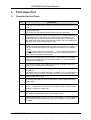
Checklist for first Tests
Instruction
STEP
1
Test SIM-card with a handy, decide if you want to use a PIN-code or not and
note it.
2
Connect Hardware
(5V-supply, RS-232-interface with 5V-levels, Antenna, SIM-card)
3
Set serial-port baud-rate of DTE to 115200 baud, 8n1, hardware-handshake
(Soft-handshake not supported). The module should react already to ATCommands, even if it is not connected to a network. If it is not reacting, try
also 9600 baud. After getting responses from modem, set it to autobaud with
‘AT+IPR=0’ and store the setting with ‘AT&W’.
4
If no SIM-PIN-code is needed, the module should be connected to the
network some seconds after power-up. (With the command ‘AT+CPIN?’ you
can test if the Module requires PIN. Response ‘SIM PIN’ for yes, ‘READY’
for no.)
If a PIN is used, enter it with 'AT+CPIN=”....”. The module answers with ‘OK’
and connects to network. It uses the providers in the ‘preferred-operatorslist’ (see AT commands interface guide).
5
Check the connection status of the modem. It can be seen by the flashing
LED (Pin 29 of Socket) and the response "+CREG: 1,1" (After issuing the
command 'AT+CREG=2').
6
The reception-quality can be seen with 'AT+CSQ'. A reception level of at
least 10 to 15 is needed for safe operation.
7
Configure the module for your needs (baud rate, information commands etc.,
see below)
Set data-mode to V110 9600 baud with 'AT+CBST=71,0,1' and configure the
other side of communication to the same. Set ‘ATS0=2’ at the other side.
8
Call the other side by 'ATD..........'.
9
If the other side calls you, set 'ATS0=2' before, so the module will answer
after 2 rings.
10
For a test-voice-call, you could call a telephone or a portable phone with
‘ATD…. ;’ (Semicolon for voice mode). A headset can be connected to the
module to speak to the other side.
11
Send an SMS to a portable. See following example:
AT+CMGS=”0764359988” <CR> Call me today <ctrl-Z>
12
Send DTMF tones to a phone. ‘AT+VTS=1’ sends digit ‘1’. Only one digit can
be transmitted with this command, so you have to repeat it to send longer
numbers.
No. AL7020S-QSM-101
Altec Electronic AG
Seite 4 / 18
AL7024S Quick Start Manual
1.2
Initialisation-Steps:
The AL7024S can store a set of parameters (please see also command “AT&W” in the
“AT command manual”). The RS232 interface parameters can also be stored. Our
Socket Modems AL7024S are preset to “AT+IPR=115200” baud rate”. You should think
about the initialisation-steps that should be made every time the AL7024S is poweredup. For details see also chapter 5.2 in the “Developer’s Guide”.
•
Power-up the AL7024S Socket-Modem
•
Pull-down the Reset-pin for at least 800ms.
•
Eventually adjust RS232-parameters.
•
Send “AT” to modem and wait for response.
•
If SIM-Pin is required, enter it with AT+CPIN=”xxxx”
•
Configure the modem to your required application:
Examples:
AT+CMEE, AT+CR, AT+CRC, ATV, AT+CREG, AT+CGREG.
(AT+CREG indicates Network-status).
Set default-storage for phone book and SMS.
For using Microphone- and Speaker-pins, you should set:
AT+MAPATH=1,2 / AT+MAPATH=2,2,1
•
For data connections the following commands / parameters are always needed:
AT+CBST
AT+MIPCALL
AT+MIPOPEN
AT+CGDCONT
for protocol-selection
for TCP/IP
for TCP/IP
for GPRS
If you want to use GPRS with Windows, you should set AT+CGDCONT
No. AL7020S-QSM-101
Altec Electronic AG
Seite 5 / 18
AL7024S Quick Start Manual
2.
Data applications
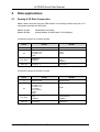
2.1
Analog V.32 Data Connection
Make a data connection from the GSM modem to an Analog modem using the V.32
modulation standard with 9600 bps.
Modem A-Side:
Modem B-Side:
GSM Modem AL7024S
Analog Modem AL4094S with V.32 (9600bps)
Connection setup from A-side to B-side:
Phase
A-Side
B-Side
0
Hardware Reset
Hardware Reset
Init
AT&F0
AT+CPIN=”xxxx”
AT+CBST=7,0,1
AT&W
AT&F0
ATS0=2
Link setup
ATDXXXXX
CONNECT
RING
RING
CONNECT
Data Link
Send Data
Send Data
Connection setup from B-side to A-side:
Phase
A-Side
0
Hardware Reset
Init
AT&F0
AT+CPIN=”xxxx”
AT+CBST=7,0,1
AT+CSNS=4
AT+FCLASS=0
ATS0=2
AT&W
B-Side
Hardware Reset
AT&F0
Link setup
RING
CONNECT
ATDTXXXXXXX
CONNECT
Data Link
Send Data
Send Data
No. AL7020S-QSM-101
Altec Electronic AG
Seite 6 / 18
AL7024S Quick Start Manual
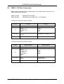
2.2
ISDN V.110 Data Connection
Make a data connection from the GSM modem to an ISDN modem using the V.110
ISDN standard with 9600 bps.
Modem A-Side:
Modem B-Side:
GSM Modem AL7024S
ISDN Modem AL5068S with V.110 (9600bps)
Connection setup from A-side to B-side:
Phase
0
A-Side
B-Side
Hardware Reset
Hardware Reset
Init
AT&F0
AT+CPIN=”xxxx”
AT+CBST=71,0,1
AT&W
AT&F0
ATS0=2
ATB0
ATN4
Link setup
ATDXXXXXXXX
CONNECT
INCOMING CALL FROM (V.110)
Data Link
Send Data
Send Data
Connection setup from B-side to A-side:
Phase
0
Modem A-Side
Modem B-Side
Hardware Reset
Hardware Reset
AT&F0
AT+CPIN=”xxxx”
AT+CBST=71,0,1
AT+CSNS=4
AT+FCLASS=0
ATS0=2
AT&W
AT&F0
ATB0
ATN4
AT&W
Link setup
RING
CONNECT
ATDTXXXXXXX
CONNECTED V.110
Data Link
Send Data
Send Data
Init
No. AL7020S-QSM-101
Altec Electronic AG
Seite 7 / 18
AL7024S Quick Start Manual
3.
Most useful AT-Commands
We have selected for you the most useful AT-Commands. They are taken from the
“Developer’s Guide/ Motorola G24 AT Commands”, which will serve you as a manual.
The selection is not complete, but it gives you an easier startup with the AL7024S
socket modem.
The page references refer to the “Developer’s Guide” edition July 2006.
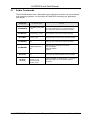
3.1
RS-232 Commands
AT Manual Pages
Command
Function
Set baud rate, e.g. AT+IPR=9600
Set auto baud:
AT+IPR=0
Baud - Rate, p. 197/199
AT+IPR /
AT+CBAUD
(Currently, the two commands have same
effect, but AT+IPR is saved
automatically)
AT+ICF
DTE-DCE char framing,
p.210
Set number of bits, parity, stop bit (8,n,1
recommended).
AT&K
DTE-DCE flow control p.
202
Hardware-flow-control, default, recommended.
SET DCD signal, p.203
See the “Developer’s Guide” (With these RS232-signals, you can change from command
to data mode, detect modem carrier, release a
call etc.)
AT&C
Result code suppression
ATQ
(quiet-mode), p.168
ATE
AT&D
Determines, whether modem sends result
codes or not
ATQ0: modem transmits result codes
ATQ1: result codes are suppressed
Echo, p.171
Determines whether modem echoes
characters received by an external application
(DTE)
ATE0: characters are not echoed
ATE1: characters are echoed
SET DTR signal, p.205
See the “Developer’s Guide” (With these RS232-signals, you can change from command
to data mode, detect modem carrier, release a
call etc.)
No. AL7020S-QSM-101
Altec Electronic AG
Seite 8 / 18
AL7024S Quick Start Manual
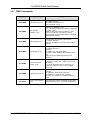
3.2
Data Commands
AT Manual Pages
Command
Function
Determines the mode of transmission
(protocol) in data connections. Connecting
GSM with:
ISDN:
AT+CBST=71,0,1
AT+CBST=70,0,1
AT+CBST
9600 baud V.110
4800 baud V.110
Bearer type selection p. 86 Analog:
AT+CBST=7,0,1
AT+CBST=6,0,1
V.32 9600 baud
V.32 4800 baud
2nd parameter: 0: async (default)
1: sync
3rd parameter: 0: transparent
1 : non-transparent (default)
AT&Q
Error-correction for async
operation, p. 89
AT&Q0: No error-correction
AT&Q5: Async with error-correction (default)
Selects bearer when incoming call does not
have information about call type.
AT+CSNS
Single Numbering
Scheme, p.89
AT+CSNS=0:Voice
AT+CSNS=2:Fax
AT+CSNS=4:Data
Sets modem into particular operating mode
(data or fax)
AT+FCLASS
Select mode, p.315
No. AL7020S-QSM-101
AT+FCLASS=0:Data
AT+FCLASS=1:Fax class 1
AT+FCLASS=2:Fax class 2
Altec Electronic AG
Seite 9 / 18
AL7024S Quick Start Manual
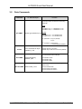
3.3
General Commands
AT Manual Pages
Command
AT+CFUN
ATD
ATD…;
Set phone functionality,
p.27
Dial command, p.60
Make a voice call
Function
Switch off Tx-circuit or RX or both etc.
nd
2 parameter causes Reset.
(You can use AT+CFUN=1,1 to force
detection of SIM-Card.)
The command is used to dial a number and
make a connection. ATD+41764445656 dials
this number and makes a data call. To make
a voice call, dial ATD….; (semicolon at the
end of number). You can also dial the special
sequences to make call forwarding etc. (see
the “Developer’s Guide”) Example to dial from
th
Phonebook: ATD>SM6 : Dial the 6 entry of
the ADN phonebook Before using the
Phonebook, you should set the AT+CPS
(Preferred Phonebook Storage).
ATD>
Dial number of phonebook
ATDL
Redial last telephone
number, p.63
Redials the last number used in the ATD
command
Answer a call, p.66
When the modem receives a call (“RING”) or
“+CRING:…”, you can accept the call with this
command, to establish the connection. (You
can set S0 with ATS0=.. to accept the call
automatically)
ATH
Hang-up command, p.65
With ATH you can disconnect the connection.
If you are in data-mode, you have to change
first from data- to command-mode (see the
next two commands)
ATO
Back to online mode p.88
Change from command mode to data mode
+++
Back to command mode
Enter “+++” during data mode and the modem
changes to data mode.
ATS0
Automatic Answer, p.262
Controls the modem’s automatic answering
mode.
ATS0=0: no automatic answer
ATS0=2: answering after 2 rings
AT&W[n]
Save configuration, p.293
AT&F[n]
Restore factory settings,
p.266
Restores the profile settings from EEPROM,
(from profile n. AT&F is profile 0.
Repeat last command,
p.246
Repeats the previous command
ATA
A/
No. AL7020S-QSM-101
Saves active profile to profile-nr. n
AT&W saves to profile 0.
Altec Electronic AG
Seite 10 / 18
AL7024S Quick Start Manual
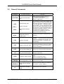
3.4
Information Commands
AT Manual pages
Command
AT&V
Display configuration,
p.291
Function
Display the modem configuration.
(Actual configuration, profile 0, profile 1)
Used to see various types of information
Request identification
information, p.51
ATI3: Product title
ATI5: Software architecture
ATI7: product description
AT+CGMR
Request revision
identification, p.47
Display firmware revision number
AT+CGMM
Request model
identification, p.46
Display supported frequency bands
AT+CGSN
Request IMEI-Nr. p.47
Display serial-number (IMEI-Nr.)
AT+GCAP
Capabilities list, p.200
Get the list of capabilities
ATI
AT+CGCLASS
GPRS mobile station
class, p.297
Set the modem to a Class or return current
class
AT+CGCLASS? : returns current GPRS class
AT+CGCLASS=”CG”:set modem to GPRS only
mode
DCE response format,
p.257
Result codes as words or as numbers
ATV0: numbers
ATV1: words (default)
AT+CMEE
Report Mobile
Equipment errors, p.274
Select, if “ERROR” or Error with error-number
is displayed
AT+CMEE=0: disable Error reports (“ERROR”
displayed)
AT+CMEE=1: enable Error reports (Errornumber displayed)
AT+CEER
Extended Error Report,
p. 279
This command gives the reason of failure of the
last call-setup or answering-attempt.
ATV
AT+CR
AT+CRC
Service reporting
control, p.110
Cellular result codes,
p.67
No. AL7020S-QSM-101
Reports detailed type of data connection, if
enabled.
AT+CR=0: extended reports disabled
AT+CR=1: extended reports enabled
Gives more detailed ring information for
incoming call.
E.g. “+CRING:VOICE”
AT+CRC=0: disable extended reports
AT+CRC=1: enable extended reports
Altec Electronic AG
Seite 11 / 18
AL7024S Quick Start Manual
3.5
Security Commands
AT Manual pages
Command
Function
This command is used to enter all types of
Passwords (CHV1/CHV2/PUK1/PUK2 etc.)
AT+CPIN
Enter PIN, p.247
AT+CPIN?: Ask modem, which pin is required.
If none is required, response is “READY”,
If normal SIM-pin to switch on modem is
required,
the response is: “SIM PIN”
AT+CPIN=”1473” : Enter the SIM PIN 1473.
After entering this pin, Modem connects to the
network.
For use of other pins, see the “Developer’s
Guide”
AT+CLCK
AT+CPWD
Facility lock, p.253
Lock, unlock and interrogate a modem or
network facility.
This command is very extensive, you can block
or allow all kinds of calls and modes. The
following example shows how to enable and
disable the SIM pin.
AT+CLCK=”SC”,0,”1473” :disable SIM pin
AT+CLCK=”SC”,1,”1473” :enable SIM pin
(with pin 1473)
Change password,
p.250
Change password
AT+CPWD=”<fac>”,”<oldpwd>”,”<newpwd>”
Example:
AT+CPWD=”SC”,”1473”,”5555” :change from
1473 to 55555
No. AL7020S-QSM-101
Altec Electronic AG
Seite 12 / 18
AL7024S Quick Start Manual
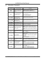
3.6
Network Commands
AT Manual pages
Command
Function
Network registration,
p.187
Command gives information about the network
registration status.
The registration status can be asked once with
AT+CREG? or you can enable a continuous
indication of the registration status with
AT+CREG=1 or AT+CREG=2.
Response: +CREG:<mode>,<status>. The
status of the registration is 1 if registered to
home network, 2 if modem is trying to register
and 0 if not trying to register. For more
information consult the ”Developer’s Guide”
AT+COPS
Operator selection, p.191
This command is used to choose a network
operator. If the modem does not register to
network at startup, try the command
AT+COPS=0. It is the command to register
automatically to the home network.
AT+COPS=? Shows the available network
operators. For better explanation of the
command consult the ”Developer’s Guide”.
AT+CPOL
Preferred operator list,
p.194
Command to edit the preferred list of network
operators on SIM
AT+CSQ
Signal Quality, p.184
Command to measure the received signal
quality. A value of about 8-12 is required to
make safe connection.
AT+CLIP
Calling Line Identification,
p. 70
The number of incoming caller is shown. If in
phonebook, the entry is shown.
AT+CLIR
Calling Line Id.
Restriction, p. 83
Controls whether own number is shown at
called side.
AT+CREG
No. AL7020S-QSM-101
Altec Electronic AG
Seite 13 / 18
AL7024S Quick Start Manual
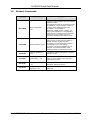
3.7
Audio Commands
The AL7024S Module have a Microphone and a Speaker pin which can be connected
to an externally headset. You should set AT+MAPATH according your application.
(See below)
Command
AT+MAPATH
AT Manual pages
Function
For the AL7024S, set AT+MAPATH=1,2 (HeadsetSets analog audio paths.
mic.) and AT+MAPATH=2,2,1 (Headset-spkr for
P. 231
voice.) Set alert, ring etc according your needs.
Volume setting, p.235
See “developer’s guide” for details. Only audio-output
on AL7020S is connected to headset-speaker.
Microphone Mute
Control, p.230
Mutes/unmutes currently active microphone-input.
AT+MAMUT
Input devices mute, p.
239
Muting of every input-device can be controlled
AT+MAFEAT
Features Selection, p.
238
Features can be switched-on and off as
Echo cancellation
Noise cancellation
Sidetone
Loudspeaker-volume p.
243.
The volume of internal speaker can be controlled.
Set DTMF Tone
Duration, p. 227
Send one DTMF
number, P.228
DTMF commands. To send number “1”: AT+VTS=1
Only single digits can be transmitted with this
command
AT+MAVOL
AT+CMUT
AT+CLVL
AT+VTD
AT+VTS
No. AL7020S-QSM-101
Altec Electronic AG
Seite 14 / 18
AL7024S Quick Start Manual
3.8
SMS Commands
Command
AT Manual pages
Function
AT+CMGS
Send message, p.178
Send SMS. Example:
AT+CMGS=”0764537865”<cr>
This is test SMS <ctrl-Z>
New message
indication, p.164
Example: AT+CNMI=2,1,0,0,0
Now, if an SMS is arriving, the following is displayed:
AT+CMTI: “SM”,2
Meaning: SMS was stored in location 2 of “SM”memory on SIM-Card. The memory used for
receiving SMS can be changed with the AT+CPMS
command. (see below)
Read message, p.171
Read message from memory selected with
AT+CPMS command
Example: AT+CMGR=2 : read the second SMS in
memory
List message, p.169
Read messages from memory selected with
AT+CPMS command.
Example:
AT+CMGL=”ALL” list all messages
AT+CMGL=”REC UNREAD” list unread received
msg.
There are more possible parameters for this
command
Preferred Message
Storage, p.160
The storage memory for messages can be selected.
Example: AT+CPMS=”SM” (“SM” being the most
usual mem.)
For a list of all possible memory areas see “AT
Commands Interface Guide”, p.70 (AT+CPBS
command)
AT+CMGD
Delete message, p.176
Delete message from preferred message storage.
Example:
AT+CMGD=2 : delete second message
AT+CMGD=1,1: delete all read messages
For exact use, consult “AT Commands Interface
Guide”
AT+CSCA
Service center address,
p.162
Enter the phone number of the SMS service center
(network operator). E.g.: AT+CSCA=”0796664444”
AT+CNMI
AT+CMGR
AT+CMGL
AT+CPMS
No. AL7020S-QSM-101
Altec Electronic AG
Seite 15 / 18
AL7024S Quick Start Manual
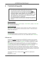
4.
Troubleshooting-guide
There is never a simple "no connection". There are many causes for
this, which can be excluded step-by-step. If you never had a
successful data-connection, you should test first with an analog
modem at the other side. Also, if possible, avoid problems with local
company-exchanges, using a direct phone-line. This applies specially
if you call to a digital "modem" (ISDN-TA). You can test these
configurations later. It is also helpful, to test different numbers on both
sides. (ISDN/analog, direct/local exchange, mobile phone on called
side. Different providers for GSM-Module.
It is very recommended to make all tests in both directions, because in
many cases of failure, the other direction is working. This helps to find
the error.
SIM-card recognized?
SIM-card can be tested by AT+CPIN? Answer: +CPIN: READY. (Answer :+CPIN: SIM
PIN : you should enter PIN first).
Verify the signal-quality
with AT+CSQ?. (repeat command a couple of times every 10secs.) It should never
drop below 10, critical connections could work down to about 7. Find best antennalocation with mobile phone.
Network-attached?
To control that the module is connected to the network, you see the response of
AT+CREG with the HEX-info about the cell. (First, enable CREG with AT+CREG=2)
DTE-baud-rates
Control if on both sides the data-rate of the DTE-DCE connection (of the computerterminal) is set higher than 9600 (best is 115200 as default for all applications). The
GSM-module can stay at autobaud (AT+IPR=0). For GPRS, set data-rate to 115200
baud.
If your application will work with lower DTE-rates, you can test these settings of
AT+CBST later, because 9600 is the standard of many modems. (19200/2400/1200
not working always). Set baud-rate on GSM-Module: use AT+IPR command.
Regarding hyper-terminal: We made bad experiences with it, sometimes it hangs up
and there is no comfort. We use Procomm 4.8 from Symantec, there you can also write
very comfortable scripts with window-support. Also as a dumb terminal, it is much more
reliable. They have also very good support in one day.
The following steps apply to analog-modems and ISDN-TA's (digital phoneconnection).
Exceptions are marked.
No. AL7020S-QSM-101
Altec Electronic AG
Seite 16 / 18
AL7024S Quick Start Manual
Ringing
To test this, call first to a normal telephone and look, if it is ringing. (ATDxxx; with
semicolon for speech-mode). Call also from telephone to GSM.
(Response RING or INCOMING SPEECH CALL)
(This is to see, if the GSM-network connects, or if it is a problem with numbering of
house-exchange, or bad configured ISDN-phones)
Make speech-connection to phone
Do the same and pick the phone up, the GSM should show "CONNECT (SPEECH)". In
the other direction, wait the GSM-module indicating the ring and enter "ATA". Now a
CONNECT should show up. At this step you can also test a headset connected to the
GSM-Module.
Configure both sides for data-transmission:
- Set ATS0=2 at both sides, so calls are answered after 2 rings.
- Set AT+CSNS=4 / AT+FCLASS=0 at GSM Modem (data mode), specially if you want
to receive call with GSM.
- Set data-protocol:
- GSM to ISDN-TA: AT+CBST=71,0,1 (9600 V.110) . Other TA must be set to
V.110 (9600 or higher), other protocols don't work.
- GSM to Analog-Modem: AT+CBST=7,0,1 (V.32 9600 baud) (ev. set analog-modem
accordingly).
After the settings, save them with AT&W.
If the other side is an ISDN-TA, this needs an MSN-number to be stored. You could
disconnect the ISDN-phone used in step above and set the TA to the same MSN as
the phone.
No. AL7020S-QSM-101
Altec Electronic AG
Seite 17 / 18
AL7024S Quick Start Manual
Make data-connection
Connect a speaker or a phone to the analog-line to obtain more information about
the progress of the connection.(hear the ring and the progress of connection buildup.)
Make call in data-mode (ATD without semicolon).
Control, if it is ringing ("RING" response), ring on phone or speaker.
Control, if call is answered (ring stops, data-sounds can be heard. ISDN: connectresponse on terminals.) Eventually, connection disconnects again.
Causes:
a. analog: Normally the setting of the Analog-modem is not important, but is
has to be set to autodetect and the fastest protocol. Alternatively it could
also be tested with setting exactly the protocol you will use. (AnalogModems from Altec: use the AT+MS=xxx command. (Specially if you have
troubles calling from Analog to GSM.)
b. analog and ISDN: possibly incompatible settings of protocol and speed. If
calling to GSM, the GSM should expect a data-call. (Settings
AT+CBST=xxx, AT+CSNS=4, AT+FCLASS=0, see above). It is advisable to
check with different GSM network-providers and in both calling directions, in
our experience this could sometimes solve the problem. For ISDN we had
less problems calling from ISDN to GSM. For Analog the direction GSM>Analog caused fewer problems.
c. ISDN: additionally there comes the influence of the fixed-networks. Normally
the public digital network allows data-transmission, but it could be that the
local extension of the company-exchange is not activated for datatransmission. (see error-messages at GSM-side)
Remarks for Swiss Customers
There are some differences between the GSM-Network-providers.
-
Generally speaking, we had better results connecting to and from ISDN using SIMCard from Sunrise.
On the other hand, with Analog-Modem (V.32) you better use Swisscom. With Sunrise
we were only able to originate a V32-call, but not to receive one. Nevertheless, Sunrise
informed us, that it should be possible.
Not tests were made with Orange (coming soon).
No. AL7020S-QSM-101
Altec Electronic AG
Seite 18 / 18