1
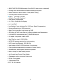
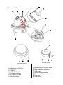
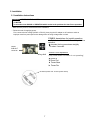
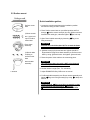
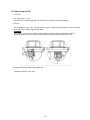
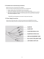
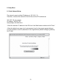
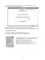
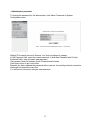
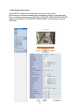
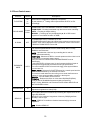
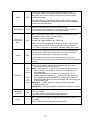
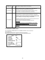
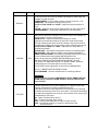
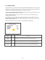
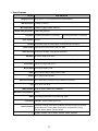
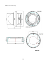
Full Manual 1/2.9" Network Camera PXD-2080Z03 B Table of contents 1. Safety Instructions and Notes…....................................................................................................... 4. Part names…………………………….…...................................................…………………………... 3 3 5 6 5. Installation Instructions......................................................................................……………………... 7 6. Setup Menu ……………............................................................................…………………………... 13 2. General Descriptions............................................................................……………………………... 3. Supplied Items......................................................................................……………………………... 7. Specifications ……………………………………………….................................................................. 28 8. Dimensional Drawings ……………………………………………..........................................................30 1 WARNING To prevent fire or shock hazard, do not expose the unit to rain or moisture. The symbol is intended to alert the user to the presence of important operating and maintenance(servicing) instructions in the literature accompanying the unit. The symbol is intended to alert the user to the presence of uninsulated "dangerous voltage" within the product's enclosure that may be of sufficient magnitude to constitute a risk of electric shock to persons. Caution To prevent electric shocks and risk of fire hazards, do NOT use other than specific power source. Warning(NTSC version) -- This equipment has been tested and found to comply with the limits for a Class A digital device, pursuant to part 15 of the FCC Rules. These limits are designed to provide reasonable protection against harmful interference when the equipment is operated in a commercial environment. This equipment generates, uses, and can radiate radio frequency energy and, if not installed and used in accordance with the instruction manual, may cause harmful interference to radio communications. Operation of this equipment in a residential area is likely to cause harmful interference in which case the user will be required to correct the interference at his own expense. Caution -- Any changes or modifications in construction of this device which are not expressly approved by the party responsible for compliance could void the user's authority to operate the equipment. Mains power quality should be that of a typical commercial environment. If the user of the model requires continued operation during power mains interruptions, it is recommended that the model be powered from an uninterruptible power supply (UPS) or a battery.” Notice -- The images used in manual are processed to help comprehension and may differ from actual appearance of the camera. WARNING NEVER USE THIS CAMERA 1. IN WATER. 2. IN AREA WHERE HAS SHOCK OR VIBRATION WHICH RESULTS IN THE PROBLEM FOR AUTO FOCUSING. 2 1. Safety Instructions and Notes • Please read this safety and operating instructions before putting the camera into operation. • Keep the manual in a safe place for later reference. • Pay attention to safety when laying the connection cable and observe that the cable is not subjected to heavy loads, kinks or damage and no moisture can get in. • Never open the device such as boards or lens. The warranty becomes void if repairs are undertaken by unauthorized persons. • Maintenance and repair have to be carried out only by authorized service centers. • Use only a mild detergent to clean the housing. • Keep clean the window surface from the dirt or dust, which may reflect the infrared light to the lens at night.. • The camera should never be operated beyond the technical specifications. This can lead to destruction. • The camera should never be operated in water. 2. General Descriptions This Network camera realizes the natural and crisp image as you see the scene in front of you by adopting Auto Focus Full HD(1920x1080p) camera module. Highly detailed pictures can be achieved and color reproducibility deserves attention. With 3X Optical Zoom and 32X Digital Zoom, - Offers the flexible observation - Provides max. 96X zoom With ICR mechanism, - Enhances its sensitivity about 10X at night time - Can accepts the infrared light With 24VAC/12VDC dual power design, - Offers the flexibility of installation - Ensures the reliability Main features are; • Onvif / PSIA Conformance • Optical 3X Auto Focus Zoom • Digital 32X Zoom • f3~9mm, 3X Day & Night Zoom Lens • 1920x1080p(30fps/25fps) • Wide Dynamic Range • Sense Up(~x8) / AGC(0~20) / 3D Noise Reduction 3 • SMART MOTION ZOOM(Automatic Zoom IN/OUT when motion is detected) • Pointing Zoom which enables the flexible zooming at any area • Motion Detection / Motion Deblur / Privacy Mask / Defog • Focusing Status Indicator on Screen - (Blue) Focusing in process - (White) Focusing Completed • Pixel Defect Compensation • ID / TITLE / ZOOM RATIO Display • H / V / HV FLIP • Lens Refresh / Lens Initializing Set / LSC(Lens Shade Compensation) • Enhanced Sensitivity by DSS technology • Menu Control via either Local Joystick or WEB • OSD Menu & CVBS Video Sub-out for Easy installation and Maintenance • H.264/MJPEG dual streaming with TI DM365/368 engine • Full duplex 2 way Audio, Alarm IN/OUT • Max 30fps live view @ 1920x1080p • MICRO SD memory card slot for Local recording • PoE (Power Over Ethernet), IEEE 802.3af • Input voltage: 24VAC/12VDC dual type of Local power • Circuit protection against faulty connection in Power Polarity • Isolated power supply against ground loop problem. • Built in cooling Fan and Heating function • Anti-Scratch Hard Coated Clear Bubble • Changeable surface mount and flush mount • Perfect 3-Axis gimbal • 2 High power LEDs • IP 67 / IK 10 Protection 4 3. Supplied Items • 1x MegaPixel Network AF Zoom Camera • 1x Installation and Operating Instructions • 1x ①Pipe hole cap • 1x ②Pipe Spacer • 1x ③L-shape hex wrench • 3x ④Wrench Bolt for surface mount • 4x ⑤Anchors • 4x ⑥Mount screws • 1x ⑦BM Screw • 1x ⑧Sub-out cable • 1x ⑨Coupler for RJ45 Cable • 1x ⑩EMI Ferrite Core ⑤ ② ⑦ ⑨ 5 ⑧ ⑥ ④ ③ ① ⑩ ⓓ 4. Control and Part names ⓐ ⓑ ⓔ ⓒ ⓕ ⓖ ⓗ ⓘ ⓝ ⓙ ⓚ ⓜ ⓛ ⓟ Surface Mount Base Dome Bubble Assembly ⓐ ⓑ ⓒ ⓓ ⓔ ⓕ ⓖ ⓗ ⓞ Lens Light sensor for IR LEDs IR LEDs IP RESET MICRO SD Card Slot RTx Status Indicator OSD control joy stick Video Sub-output ⓘ ⓙ ⓚ ⓛ ⓜ ⓝ ⓞ ⓟ 6 Mount holes(x3) for dome base Clear bubble Ring cover fixing screws(x3) Ring cover Surface mount holes(x4) Dome base fixing screw taps(x3) Pipe hole Pipe spacer 5. Installation 5.1 Installation Instructions WARNING NEVER USE THIS CAMERA 1) in WATER. 2) in area where has SHOCK or VIBRATION which results in the problems for Auto Focus operation. • Make sure the power is removed before the installation. • Follow the order for applying power. First, connect the low voltage (AC24V or DC12V), then plug the AC adapter to AC outlets to avoid an improper reset from power jitter and a damage from the surge voltage when no load. SYMBOL descriptions for joystick operation; -▲,▼,◀,▶ denotes the directions of Joystick lever operation. -☟ denotes the long press down straightly for about 2 seconds. VIDEO SUB-OUT connector Joy stick Zoom & Focus Adjustment (Only works when OSD Menu is not operating) ▲ Zoom In ▼ Zoom Out ◀ Focus Near ▶ Focus Far IP Reset (Press over 10 sec by stick driver) 7 5.2 Surface mount Ceiling or wall Quick installation guides; Surface mount base 1. Locate the mounting template at the installation position and drill the ceiling or wall if needed. ⑥Mount screws 2. Place Surface mount base on pre-drilled position and fix it through ⓙSurface mount holes(x4) by using ⑥Mount screws. Assemble the cable pipe, otherwise tighten ①pipe hole cap. and ②pipe hole cap for surface mount base 3. Open Dome bubble assembly by loosening ⓘRing cover fixing screws(x3) Dome base assembly ④Wrench bolts for fitting to surface mount base Dome bubble assembly CAUTION Extreme care should be taken NOT to scratch the dome surfaces and to protect it from dirt or dust at any time. 4. ⓕMount holes(x3) for dome base and ⓚhole should be aligned before fixing Dome base assembly to Surface mount base by using ④Wrench bolts. And tighten ④wrench bolts 5. Route the power/ video cable to the connecting place. CAUTION Care should be taken the cable is NOT to be damaged, kinked or exposed in the hazardous area. 6. Set the camera’s angle (Pan, Tilt, inclination) L-Wrench 7. Adjust ZOOM/FOCUS by OSD menu or manual 8. Put Dome bubble assembly over Dome camera assembly and tighten ⓗRing cover fixing screws(x3) by using ③L-shape hex wrench CAUTION Tighten enough ⓗRing cover fixing screws(x3) so that there should be NO gap between ⓔLens and ⓖClear bubble to avoid the light inflow from IR LEDs. 8 5.3 Flush mount Ceiling or wall Quick installation guides; 1. Locate the mounting template at the installation position and drill the ceiling or wall if needed. Dome base assembly ⑥Mount screws Dome bubble assembly 2. Open Dome bubble assembly by loosening ⓘRing cover fixing screws(x3) CAUTION Extreme care should be taken NOT to scratch the dome surfaces and to protect it from dirt or dust at any time. 3. Place Dome base assembly on pre-drilled position and fix it through ⓕmount holes(x3) by using ⑥Mount screws. (Use three screws only out of ⑥Mount screws(4x)) 4. Route the power/ video cable to the connecting place. L-Wrench CAUTION Care should be taken the cable is NOT to be damaged, kinked or exposed in the hazardous area. 5. Set the camera’s angle (Pan, Tilt, inclination) 6. Adjust ZOOM/FOCUS by OSD menu or manual 7. Put Dome bubble assembly over Dome camera assembly and tighten ⓗRing cover fixing screws(x3) by using ③L-shape hex wrench CAUTION Tighten enough ⓗRing cover fixing screws(x3) so that there should be NO gap between ⓔLens and ⓖClear bubble to avoid the light inflow from IR LEDs. 9 5.4 Limit of pan and tilt 1. Pan limit Pan is limited to +/- 165°. Do NOT force to rotate the gimbal over the limit to prevent from the internal damage. 2. Tilt limit Tilt is limited to 15° min ~ 90° max. with reference to the ceiling when the inclination of camera module is 0°, that is, the image is aligned horizontally. CAUTION : Tilt may NOT reach 15° min. if some IR light reflects to the lens when the inclination is NOT 0°. When Tilt is set to near the minimum limit, examine and verify that NO IR refection occurs. 3. Inclination limit (Horizontal image alignment) Inclination limited to +/-60° max. 10 5.5 Installation and commissioning Instructions • Make sure the power is removed before the installation. • After all connections are finished properly, follow the order for applying power. a) Plug the network cable into RJ-45 Ethernet Port at the rear panel. If PoE is the unique power, there will be no need to connect Power terminal. b) When DC12V or AC24V Local power is necessary, first connect the low voltage (DC12V or AC24V), then plug the AC adapter to AC outlets to avoid an improper reset from power jitter and a damage from the surge voltage when no load. ※When PoE and Local power are connected, Local power has priority. 5.6 Power Supply Connections Camera can work with either 24AC or 12VDC, dual voltage power and PoE(IEEE Std. 802.3af). Primary and secondary grounds are completely isolated to avoid the possible ground-loop problems. 11 5.2.1 EMI Ferrite Core Connections Please connect EMI Ferrite Core as below photos. 50mm 50mm 12 6. Setup Menu 6.1 Quick Network Setup The network camera‘s default IP address is: 192.168.1.10. Therefore, to access the camera for the first time, set the PC‘s address as 192.168.1.XX; for example: IP Address: 192.168.1.20 Subnet Mask: 255.255.255.0 • Enter the camera’s IP address in the URL bar of the Web browser window and hit “Enter.” • Enter the default user name (root) and password (root) in the prompt request dialogue. It is also possible to reset IP parameters to the original factory default settings by pressing the IP reset 13 If the Information message doesn‘t come out due to the problems like network failure, you can start the manual installation. Click the Install ActiveX Control, and the pop-up window will be displayed. After the installation is successfully completed, Smart Viewer window will be displayed. - Assigning an IP address To assign an IP address to the camera proceeded as follows: Click Network Configuration on the Network Configuration menu. 14 Depending on the service type, the network configuration can be in any of Static IP, DHCP Client, or PPPoE. You need to set up the network camera according to your network type. For static IP, select static IP and input values for IP address, NetMask, Gateway, DNS1, DNS2 and click apply for saving settings. After apply, program will ask closing web browser for updates, which will take 20~30 seconds. For DHCP, DHCP server must exist in the same network environment. Select DHCP Client from Network Configuration, click Apply. 15 PPPoE is used to connect IPproducts to PPPoE modem provided by ISP. Since PPPoE needs verification, ID and password are necessary to access network. Type in ID and password. 16 - Administrator password To change the password for the administrator, click Admin Password on System Configuration menu. Default ID for admin account is fixed as “root” and not allowed to change. In Old Password field, enter the current password. In both New Password and Confirm Password fields, enter the same new password. The password must be between 4 and 23 alphanumeric letters. Click Apply button to put it into effect. Because you have replaced the password with a new one, the existing network connection made with old password now is lost. You will have to reconnect using the new password. 17 - Accessing the setup menu Camera SETUP menu can be accessed in two ways via web viewer. Most frequent controls are available with the parameters directly in the below table. More complicated settings such as PRIVACY, POINTING ZOOM & SMART MOTION settings are available via ‘ADVANCED CAMERA MENU’ by activating the camera OSD menu. 18 6.2 Direct Control menu SPECIAL Default TV SYSTEM US or EU Descriptions Selects HDTV standards for US(60HZ) or EU(50HZ). nd By this selection, 2 analog video output switches to NTSC or PAL accordingly. ZOOM PUSH, AUTO and MANUAL modes are available for focusing. FOCUS MODE D-ZOOM ZOOM PUSH OFF ZOOM PUSH – Focusing is activated only when zoom in/out is working. AUTO – Focusing is always working. MANUAL – Focusing can only be adjusted by ▲,▼ of OSD control joystick or Focus Near/Far button on WEB. D-ZOOM(Digital zoom) is available up to 32x. D-ZOOM starts working when the optical zoom reaches its maximum teleposition. Zoom ratio is displayed on the right bottom corner of the monitor if DISPLAY ZOOM RATIO is set to ON. Can set EXPOSURE MODE to AUTO, IRIS Priority, SHUT. Priority, MANUAL and Flickerless. EXPOSURE MODE AUTO AUTO – Optimizes the video level by controlling the iris and the shutter speed automatically. IRIS Priority – Selects to fix IRIS in a certain aperture and the video level is controlled by an automatic shutter control. IRIS Level menu is activated when EXPOSURE MODE is set to IRIS Priority. Lower IRIS LEVEL will close more Iris and increase the field of depth in the daytime but significantly decrease the low light performance. Too much low IRIS LEVEL will result in the foggy video by the diffusion from the lens iris. SHUT. Priority - Selects to fix SHUTTER speed in a certain speed and the video level is controlled by an automatic iris control. This mode is useful when the color rolling occurs under the fluorescent lighting. It is not recommendable at outdoor in the daytime. MANUAL – Iris and Shutter can be set to fix. Flickerless – Reduces the flicker in video when US(60Hz)/EU(50Hz) mode is used in 50Hz/60Hz fluorescent lighting respectively. SHUT. Priority, MANUAL and Flickerless modes disable SENS-UP and MOTION BLUR functions. BRIGHTNESS SENS-UP 10 AUTO Adjusts the brightness of video(0~20). The brighter video can be obtained by increasing the exposure time in the night with SENS-UP. SENS-UP is the maximum integrations of frame by DSS(Digital Slow Shutter) in the low light. AUTO – SENS-UP is enabled or disabled automatically by the scene brightness. OFF – Disables SENS-UP. 19 Improves the visibility for the high bright area and the dark area by the double captures of image with LONG and SHORT exposures. With WDR ON, the frame rate becomes half by the double captures. WDR OFF WDR Weight MID Back Light Compensation (BLC) OFF ※CVBS video signal Connecting 2nd video to CVBS port disables WDR function temporary. It should be considered when installer adjusts the video with installation monitor via CVBS video signal. WDR level can be selected from LOW, MID and HIGH. Care should be taken to select this mode because video may lose its quality in some environments by the over compensation. ON – Improves the visibility for the dark object by the bright back light. Outside area of BLC window can over saturate. Available to set BLC POSITION at ADVANCED CAMERA MENU> BLC POSITION HLC – Cuts out the highlight area with black mask and excludes it from compensation. Lower HLC LEVEL cut out video from the lower level. HLC LEVEL is adjustable at ADVANCED CAMERA MENU>HLC LEVEL 3D-NR is a very sophisticated and powerful time-based noise reduction technology by monitoring the noise for the several video frames and defining and eliminating them consecutively at low light. 3D-NR MID Higher setting reduces noise much more but results in losing the sharpness and the tail effect or the motion blur for the fast moving target at low light. EXT for IR LED DAY/NIGHT AUTO for No IR LED Day & Night Threshold High AGC 12 EXT – DAY or NIGHT is determined by the built-in light photo sensor. Camera with IR LED must be set to EXT. AUTO – Used when DAY or NIGHT is determined by light level through the lens and DAY from/to NIGHT is switched automatically by the scene brightness. When EXPOSURE>AGC is less than 12, DAY/NIGHT AUTO is disabled and forcibly switches to ___(DAY) to avoid the malfunction. EXT, B/W(NIGHT) and COLOR(DAY) is independent on AGC level. When EXTERNAL IR LED is used with NON IR LED model, please set to IR LED MODE ON. B/W(NIGHT) – Forcibly removes IR cut filter and switches to B/W regardless of light level. COLOR(DAY) – Forcibly DAY/NIGHT is disabled and outputs color video. D<-->N Threshold is a threshold level and Gap to switch from DAY to NIGHT. Low makes camera entered NIGHT at lower light level. High makes camera exited NIGHT at brighter light level. AGC amplifies the video gain for brighter video but noise and white pixel accordingly. AGC level less than 10 disables AUTO in DAY/NIGHT. 20 ATW, ONE PUSH and MANUAL are available for the white balance modes. WHITE BAL ATW WB Manual R-Gain 10 ATW – White balance is continuously working along with the color temperature changes in the range of 2,000K~8,500K. ONE PUSH- White balance works only when ONE PUSH is selected. MANUAL –This mode can be used only when the color temperature does not vary. White balance is fixed to the settings by R_GAIN and BGAIN. Activates when WHITE BALANCE is set to MANUAL. Adjustable 0~20. WB Manual B-Gain 10 Sharpness 10 Adjusts the sharpness of video. Color Gain 10 Adjusts the color level of video. Gamma 0.5 Adjusts the gamma of video. Reverses the video left and right and/or up and down by MIRROR/FLIP. Mirror/Flip NO No Mirror, No Flip – Normal display without mirroring or flipping No Mirror, Flip – Video is reversed upside down. Mirror, No Flip Ver. – Video is reversed left and right. Mirror, Flip HV – Video is reversed left and right and upside down. When the video is reversed by Ver. or HV, then the joystick directions are reversed accordingly. This feature is very useful when a camera in installed in upside dawn. Defog OFF AUTO – Enhance the foggy video automatically according to status of scene MANUAL – Sets to enhance the foggy video manually regardless of status of scene Defog Weight MID LEVEL – LOW, MID, HIGH Video quality can be less in normal environments. Display Zoom Ratio OFF ON enables to display the zoom ratio on the bottom right corner. OZx.x appears during the optical zoom and DZx.x will display by multiplying the optical zoom ratio and the actual digital zoom ratio. Display Focus Indicator ON ON enables to display the Focus Indicator on Monitor. Display ID OFF ON enables to display Camera ID on Monitor. 21 Display Title IR LED Mode OFF ON enables to display Camera Title on Monitor. OFF IR LED Control(AUTO/OFF) is available with IR LED model only. If IR LED is set to OFF, IR LED will be turned OFF but DAY or NIGHT is still determined by the built-in light photo sensor. IR LED Mode is workable with IR LED built-in model only. Lens initialization is necessary during the installation or the regular operation to align the position data with the mechanical positions whose lens elements may move and deviate from its calibrated position by the shock or vibration, for example, during the transportation. LENS INIT checks the positions for zoom and focus at both of the end positions and saves them for the references. Lens initialization is automatically executed at power up. Lens Initialize CAUTION I It is strongly necessary to execute LENS INIT in cases below; 1) At the final step for the installation. 2) When focus becomes out of control by the shock or vibration. 6.3 ADVANCED CAMERA menu Click ‘ADVANCED CAMERA MENU’ bar at CAMERA CONTROL menu to activate the camera OSD menu. Click Up/Down/Left/Right bars to navigate or change the parameters. These options have been pre-configured at the factory for optimal performance. MENU V3.07 1. PRIVACY ↵ 2. MOTION OFF↵ 3. TITLE SET ↵ 4. SMART IR |::::::::::::::| 0 5. MOTION DEBLUR ON 6. HLC LEVEL |:::::::|::::::| 10 7. BLC POSITION SET 8. POINTING ZOOM ↵ 9. EXIT SAVE&EXIT↵ 22 SPECIAL PRIVACY MOTION Default - OFF Descriptions 10 Privacy zones which can be enabled individually by ZONE DISP are available to mask the video. ZONE NUMBER – Set a number to select a privacy zone from 1~10. ZONE DISP – ON enables a relevant privacy zone. H-POS, V-POS, H-SIZE and V-SIZE – Adjust the size and position of zone. COLOR – Select the color used for masking the zone form eight colors. TRANSPARENCY – Defines the transparency for the mask zone. MOTION can detect the changes in the motion window and displays the results in blocks and/or a text message. SENSITIVITY – Adjusts the detection sensitivity for motion. High value increases the sensitivity to detect the small motion easily. Too high sensitivity will cause the erratic detection by the tree leaves or the light level changes and too low setting will fail in detecting the motion H-POS,V-POS, H-SIZE and V-SIZE - Adjust the size and position of the detection window. BLOCK DISP – ON enables to display the blocks for the detected area. MOTION OSD – ON enables to display a text message, MOVING !!!, SMART MOTION ZOOM– ON enables to Automatic Zoom IN/OUT when motion is detected and also enables MOTION OSD to ON. Area to be zoomed in by SMART MOTION ZOOM can be set at MOTION> SMART MOTION ZOOM>ZOOM TARGET. Clicking “Up, Down, Left, Right and Enter bar” for ZOOM TARGET varies the viewing angle to be zoomed when the motion occurs. Set the video left and right and/or up and down by MIRROR/FLIP. See ‘6.3.1 SMART MOTION ZOOM’ for detail. STAY ZOOMING – Sets the duration time for zooming by Motion. CAUTION I Set the direction of video by MIRROR/FLIP before SMART MOTION ZOOM setting. Otherwise ZOOM TARGET could be different from your intention. TITLE SET - Camera title(name) can be set and edited up to 15 alpha numeric and symbolic characters from ASCII codes(ENGLISH only). Clicking the Up/ Down/ Left/ Right bars to move the cursor for choosing characters and click the Enter bar to select them. The selected characters are added and displayed on the top left corner and the cursor moves right automatically for next input. SP - Space is inserted when clicked. BS – Cursor moves back when clicked. CLR – Clears all the characters on input line when clicked. POS – Sets the title position by using four direction bars and clicked enter bar. 23 SMART IR can be set to reduce the saturation by the strong IR illumination in the night in any menu of EXT, AUTO and B/W(NIGHT) Setting SMART IR in any menu is identically applied to other menu. Zero(0) turns off SMART IR and High setting avoids the saturation strongly but the corners will be darker accordingly. SMART IR 0 MOTION DEBLUR ON ON enables MOTION DEBLUR to reduce the motion blur in a certain indoor enviroment. Noise or color rolling can increase. HLC LEVEL 10 Cuts out the highlight area with black mask and excludes it from compensation. Lower HLC LEVEL cut out video from the lower level. SET Improves the visibility for the dark object by the bright back light. Outside area of BLC window can over saturate. BLC has a target window for compensation and its size and position can be set by H-POS, V-POS, H-SIZE and V-SIZE. BLC POSITION POINTING ZOOM ON enables to set off-centered location to be the center of zoom H-POINTER, V-POINTER- Able to set the location of zoom center D-Zoom is available to ~ 32x. See ‘6.3.2 POINTING ZOOM’ for detail. - CAUTION I Set the direction of video by MIRROR/FLIP before POINTING ZOOM setting. Otherwise location of zoom center could be different from your intention. EXIT SAVE & EXIT – Exits the menu after saving the parameters. 24 6.3.1 SMART MOTION ZOOM SMART MOTION ZOOM enlarges the certain area defined by a yellow window to the full sized image when the motion is detected in the black window. SMART MOTION ZOOM window can be re-sized by adjusting D-ZOOM RATIO and moved by H-POINTER and V-POINTER. UNLIKE the conventional zoom which can zoom in/out the center area of image only, by the flexible zoom location and area, SMART MOTION ZOOM differentiate its usefulness from others. That is, a conventional camera installed on the corner of ceiling can zoom the center of the floor in a room and result in losing the image of door on the side wall. However, SMART MOTION ZOOM can be set to see the door side and zoom in that area without missing the IMPORTANT security point. SMART MOTION ZOOM H-POINTER V-POINTER O-ZOOM RATIO D-ZOOM RATIO RETURN 10 10 OX2.0 DX1.5 RET↵ SMART MOTION ZOOM Default H-POINTER 10 Moves MOTION ZOOM area(Yellow window) horizontally. V-POINTER 10 Moves MOTION ZOOM area(Yellow window) vertically. O-ZOOM RATIO OX2.0 Sets the area size to be Optical zoomed when the motion occurs in the black window D-ZOOM RATIO DX1.5 Sets the area size to be Digital zoomed when the motion occurs in the black window Descriptions 25 6.3.2 POINTING ZOOM This camera has a very useful and powerful feature, POINTING ZOOM, which can zoom in/out any area. UNLIKE the conventional zoom which can zoom in/out the center area of image only, by the flexible zoom location and area, POINTING ZOOM differentiate its usefulness from others. That is, a conventional camera installed on the corner of ceiling can zoom the center of the floor in a room and result in losing the image of door on the side wall. However, POINTING ZOOM can be set to see the door side and zoom in that area without missing the IMPORTANT security point. POINTING ZOOM can be activated by the joystick operations of ▲ for zoom in and▼ for zoom out or Zoom in/out button on WEB VIEWER while SMART MOTION ZOOM is activated by the result of motion detection in the defined area. If Zoom ratio becomes out of optical zoom ratio, it automatically turns to Digital Zoom. Set D-Zoom Pointer POINTING ZOOM H-POINTER V-POINTER RETURN OFF 10 10 RET↵ POINTING ZOOM Default POINTING ZOOM OFF H-POINTER 10 Sets the horizontal location of area to be zoomed by POINTING ZOOM. V-POINTER 10 Sets the vertical location of area to be zoomed by POINTING ZOOM. Descriptions ON enables to set off-centered location to be the center of zoom 26 7. Specifications PXD-2080Z03 B 207513 Imaging Sensor Sony Exmor 1 / 2.9” Progressive Scan CMOS Sensor Effective Pixels 1,936(H) x 1,097(V) Min. Illumination 0.0008 Lux (@AGC MAX, DSS x2) Output Video Resolution TV system Sync. System 1920x1080(30p/25p) US(60Hz)(switchable to EU(50HZ)) EU(50Hz)(switchable to US(60Hz)) Internal Format 16:9 Video format for most popular commercial HDTV monitors Video Output Ethernet thru RJ45 male & CVBS thru BNC Video Sub-out NTSC/PAL standard, 1Vpp @75Ω terminated S/N Ratio More than 50dB (AGC OFF) Lens type 3X Day & Night Zoom Lens, f3~9mm , F1.2 (wide) ~ F2.1 (tele) Zoom Ratio Optical 3X, Digital 32X Zoom Day & Night True Day & Night by ICR LEDs Built-in 2pcs x 855nm High Power IR LEDs Focus Auto / Zoom Push / Manual Exposure Control Auto / Iris-Priority / Shutter-Priority / Manual / Flickerless Flip OFF / H / V / HV FLIP White balance ATW / ATWext / ONE PUSH / MANUAL Minimum Focus Distance 0.5 m~ WDR True WDR by dual scan in two frames at 15fps. Functions NORMAL, WDR, D-WDR, BLC, HLC SMART MOTION ZOOM (Automatic Zoom IN/OUT when motion is detected), Pointing Zoom which enables the flexible zooming at any area, Special Feature Motion Detection, Privacy Mask, Pixel Defect Compensation, Defog, Title Set, Motion Deblur, Focus Indicator Language English, German, French, Italian, Spanish, Polish, Japanese 27 Power PoE(IEEE Std. 802.3af), 24V ~ 15VA / 12V, 1A DUAL POWER Circuit protection against faulty connection in Power Polarity Isolated power supply against ground loop problem Protection Rating IP67 / IK10 Mechanical Feature Changeable surface mount and flush mount / Perfect 3-Axis gimbal Installation Temperature -20ºC ~ +50 ºC (Humidity : 20%RH ~ 80%RH) Operating Temperature -30ºC ~ +50 ºC (Humidity : 20%RH ~ 80%RH) Housing Solid Aluminum Cast with Hard coated polycarbonate clear Bubble External Dimension 100mm(Ø) x 140mm(W) x 119mm(H), about 1Kg IP SPECIFICATION Video Encoding H.264 / MJPEG dual streaming Protocol HTTP, TCP/UDP/IP, ARP, ICMP, RTP/RTSP, multicast, Telnet, ftp, PPPoE, SMTP(e-mail), DHCP, NTP, uPNP, etc, ONVIF, PSIA support Transmission Control VBR, CBR ( 32K ~ 12M bps ) CMS Bundled with Full featured 16 channels PC NVR. 32/64 channels available(Option) IP Installation & Configuration: installation wizard, HTTP, telnet and console, maintenance Upgrade firmware: HTTP, telnet+ftp Connectivity Max. 16 simultaneous user connection SD memory card Slot for MICRO SD memory card up to 32GB Audio & Alarm Two way audio input /output PoE IEEE Std. 802.3af ● Design and specifications are subject to change for product improvements without prior notice. 28 8. Dimensional Drawings (Unit: mm) 29 eneo® is a registered trademark of Videor E. Hartig GmbH Exclusive distribution through specialised trade channels only. Videor E. Hartig GmbH Carl-Zeiss-Straße 8 · 63322 Rödermark/Germany Tel. +49 (0) 6074 / 888-0 · Fax +49 (0) 6074 / 888-100 www.videor.com www.eneo-security.com Technical changes reserved © Copyright by Videor E. Hartig GmbH 06/2014


![[B40] RWS-TE2PAFZ39-IR(Videor)](http://vs1.manualzilla.com/store/data/005979657_1-986d79b0350f507a65bc366834e972e4-150x150.png)