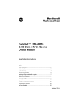
1
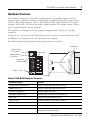
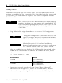
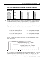
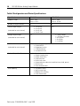
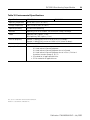
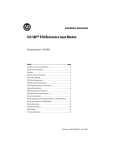
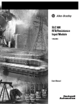
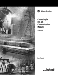
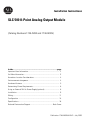
Installation Instructions
SLC 500 8-Point Analog Output Module
(Catalog Numbers 1746-NO8I and 1746-NO8V)
Inside…............................................................................................page
Important User Information .................................................................... 2
For More Information.............................................................................. 3
Hazardous Location Considerations ....................................................... 4
Environnements dangereux .................................................................... 4
Hardware Features ................................................................................. 5
Determining Power Requirements.......................................................... 6
Using an External 24V dc Power Supply (optional) ................................ 6
Installation .............................................................................................. 8
Wiring ................................................................................................... 11
Configuration ........................................................................................ 14
Specifications ....................................................................................... 16
Rockwell Automation Support................................................. Back Cover
Publication 1746-IN026A-EN-P - July 2003
2
SLC 500 8-Point Analog Output Module
Important User Information
Because of the variety of uses for the products described in this publication, those responsible for the
application and use of these products must satisfy themselves that all necessary steps have been taken to
assure that each application and use meets all performance and safety requirements, including any applicable
laws, regulations, codes and standards. In no event will Rockwell Automation be responsible or liable for
indirect or consequential damage resulting from the use or application of these products.
Any illustrations, charts, sample programs, and layout examples shown in this publication are intended solely
for purposes of example. Since there are many variables and requirements associated with any particular
installation, Rockwell Automation does not assume responsibility or liability (to include intellectual property
liability) for actual use based upon the examples shown in this publication.
Allen-Bradley publication SGI-1.1, Safety Guidelines for the Application, Installation and Maintenance of
Solid-State Control (available from your local Rockwell Automation office), describes some important
differences between solid-state equipment and electromechanical devices that should be taken into
consideration when applying products such as those described in this publication.
Reproduction of the contents of this copyrighted publication, in whole or part, without written permission of
Rockwell Automation, is prohibited.
Throughout this publication, notes may be used to make you aware of safety considerations. The following
annotations and their accompanying statements help you to identify a potential hazard, avoid a potential
hazard, and recognize the consequences of a potential hazard:
WARNING
!
Identifies information about practices or circumstances that can cause an explosion in a
hazardous environment, which may lead to personal injury or death, property damage,
or economic loss.
ATTENTION
!
IMPORTANT
Identifies information about practices or circumstances that can lead to personal injury
or death, property damage, or economic loss.
Identifies information that is critical for successful application and understanding of the
product.
Publication 1746-IN026A-EN-P - July 2003
SLC 500 8-Point Analog Output Module
3
For More Information
Related Publications
Table 1 List of Related Publications for 1746-NO8I and 1746-NO8V Modules
For
Refer to this Document
Pub. No.
A more detailed description on how to install and
use your 1746-NO8 module.
SLC 500 8-Point Analog Output
Module User Manual
1746-UM026
A more detailed description on how to install and
use your modular SLC 500 system.
SLC 500 Modular Hardware Style User
Manual
1747-UM011
A more detailed description on how to install and
use your fixed SLC 500 system.
SLC 500 Fixed Hardware Style
Installation and Operation Manual
1747-6.21
A reference manual that contains status file data,
instruction set, and troubleshooting information.
SLC 500 Instruction Set Reference
Manual
1747-RM001
How to Get More Information
If you would like a manual, you can:
• download a free electronic version from the internet at
www.theautomationbookstore.com
• purchase a printed manual by:
– contacting your local distributor or Rockwell Automation representative
– visiting www.theautomationbookstore.com and placing your order
– calling 1.800.963.9548 (USA/Canada) or 001.330.725.1547 (Outside
USA/Canada)
Publication 1746-IN026A-EN-P - July 2003
4
SLC 500 8-Point Analog Output Module
Hazardous Location Considerations
This equipment is suitable for use in Class I, Division 2, Groups A, B, C, D or
non-hazardous locations only. The following WARNING statement applies to use in
hazardous locations.
WARNING
!
EXPLOSION HAZARD
• Substitution of components may impair suitability for Class
I, Division 2.
• Do not replace components or disconnect equipment
unless power has been switched off.
• Do not connect or disconnect components unless power
has been switched off.
• All wiring must comply with N.E.C. article 501-4(b).
Environnements dangereux
Cet équipement est conçu pour être utilisé dans des environnements de Classe 1,
Division 2, Groupes A, B, C, D ou non dangereux. La mise en garde suivante
s’applique à une utilisation dans des environnements dangereux.
AVERTISSEMENT
!
DANGER D’EXPLOSION
• La substitution de composants peut rendre cet équipement
impropre à une utilisation en environnement de Classe 1,
Division 2.
• Ne pas remplacer de composants ou déconnecter
l'équipement sans s'être assuré que l'alimentation est
coupée.
• Ne pas connecter ou déconnecter des composants sans
s'être assuré que l'alimentation est coupée.
Publication 1746-IN026A-EN-P - July 2003
SLC 500 8-Point Analog Output Module
5
Hardware Features
The module contains a removable terminal block, providing connection for 8
analog output channels, which are specifically designed to interface with analog
current and voltage devices. The 1746-NO8I provides eight channels of current
outputs, while the 1746-NO8V provides eight channels of voltage outputs. There
are no input channels on the module.
The module is configured via the programming software. There are no DIP
switches.
A jumper, J4, is used to select whether the 24V dc power is provided by the SLC
backplane or an optional 24V dc external power supply.
The following illustration displays the main hardware features.
Nameplate
Channel Status
LEDs (Green)
OUTPUT
Door Label
CHANNEL
STATUS
Module Status
LED (Green)
MODULE
ANALOG
I OUT 0
Removable
Terminal Block
ANL
COM 0
I OUT 2
ANL
COM 1
I OUT 3
ANL
COM 2
I OUT 4
ANL
COM 3
I OUT 5
ANL
COM 4
I OUT 6
ANL
COM 5
I OUT 7
ANL
COM 6
+24
VDC
Self-locking Tabs
RACK
ANL
COM 7
EXT
1 2 3
Cable Tie Slots
I OUT 1
DC
COM
J4 Jumper
Table 2 1746-NO8 Hardware Features
Hardware Feature
Function
Channel Status LED Indicators
Displays channel operating and fault status.
Module Status LED
Displays module operating and fault status.
Side Label (Nameplate)
Provides module information.
Removable Terminal Block
Provides physical connection to input devices.
Door Label
Permits easy terminal identification.
Cable Tie Slots
Secures and routes wiring from the module.
Self-Locking Tabs
Secures module in the chassis slot.
J4 Jumper
Selects 24V dc power source.
Nameplate
Provides module information such as catalog number, backplane
requirements, and output ranges.
Publication 1746-IN026A-EN-P - July 2003
6
SLC 500 8-Point Analog Output Module
Determining Power Requirements
The module receives its power through the SLC 500 chassis backplane from the
+5V dc/+24V dc chassis power supply. The +5V dc backplane supply powers the
SLC circuitry, and the +24V dc backplane supply powers the module analog
circuitry. The maximum current drawn by the module is shown in the table below.
Table 3 1746-NO8 Backplane Current Consumption
Specification
1746-NO8I
1746-NO8V
Backplane Current Consumption (maximum)
120 mA at 5V dc
250 mA at 24V dc
120 mA at 5V dc
160 mA at 24V dc
Backplane Current Consumption (maximum)
120 mA at 5V dc
0 mA at 24V dc
120 mA at 5V dc
0 mA at 24V dc
when Using External 24V dc Power Supply(1)
(1)
The 1746-NO8I and 1746-NO8V output modules can use an external 24V dc power supply to reduce backplane loading. To
use an external 24V dc power supply, you must set your module’s jumper J4 as indicated in the following section. To comply
with the U.L. regulation, the external power supply must be rated N.E.C. Class 2. Do not use the 24V dc user power terminal
on the chassis power supply to power the analog output module.
NOTE: The external 24V dc power supply terminal block ground connection (DC COM) is connected to the SLC power supply
ground.
Add the values shown in the table above to the requirements of all other modules
in the SLC chassis to prevent overloading the chassis power supply. Refer to your
controller’s User Manual for power supply loading calculations and worksheets.
Using an External 24V dc Power Supply (optional)
The jumper, J4, is located in the bottom right corner of the module’s circuit board
next to the power supply.
J4 jumper location
EXT
1 2 3
RACK
Publication 1746-IN026A-EN-P - July 2003
SLC 500 8-Point Analog Output Module
7
• With the jumper in the 1-2 shorted position, the module draws all of its
power from the backplane of the SLC system.
• With the jumper in the 2-3 shorted position, the module draws its 24V dc
power from the external power supply; however, the module still draws its
5V dc power from the backplane.
Module draws power
from SLC backplane
(factory setting)
1
RACK
2
3
EXT
Module draws 24V dc
power from external supply
1
RACK
2
3
EXT
Important Notes about Using an External 24V dc Power Supply
ATTENTION
!
IMPORTANT
Before setting the jumper, all system power must be turned
off. This includes the chassis power as well as any external
24V dc power supply.
If the module is configured to use an external 24V dc power
supply, the supply must be turned on for the module to
operate. If the external 24V dc power supply is turned off, the
module’s outputs will be turned off, and the module’s
processor will be reset until power is restored.
The module’s LEDs will flash the 24V Power Fail blink code.
See the troubleshooting section of the SLC 500 8-Point Analog
Output Modules User Manual, publication 1746-UM026 for
more information.
IMPORTANT
Do not use the 24V dc user power terminal on the chassis
power supply to power the analog output module.
Publication 1746-IN026A-EN-P - July 2003
8
SLC 500 8-Point Analog Output Module
Installation
Install the SLC 500 system in a properly rated (i.e., NEMA) enclosure. Make sure
that the SLC 500 system is properly grounded.
Choosing a Slot in the Chassis
Two factors determine where the analog module should be located in the chassis:
ambient temperature and electrical noise. Consider the following conditions when
selecting a slot for an analog module. Position the module:
• in a slot away from an ac or high voltage dc modules
• in the chassis closest to the bottom of the enclosure where the SLC 500
system is installed
• away from the chassis power supply if installed in a modular system
TIP
To use the advanced features of Class 3 operation, an SLC 5/02
or higher processor must be used, and the module must be
located in the local chassis or in a remote ControlNet chassis
with a 1747-ACN(R)15 adapter.
If the module is located in remote I/O chassis with a 1747-ASB
adapter, it will operate in Class 1 mode, and you must use
block transfer for configuration and data retrieval.
TIP
Remember that, in a modular system, a processor or adapter
always occupies the first slot of the chassis.
Prevent Electrostatic Discharge
ATTENTION
!
Electrostatic discharge can damage integrated circuits or
semiconductors if you touch bus connector pins. Follow these
guidelines when you handle the module:
•
•
•
•
•
•
Touch a grounded object to discharge static potential.
Wear an approved wrist-strap grounding device.
Do not touch the bus connector or connector pins.
Do not touch circuit components inside the module.
If available, use a static-safe work station.
When not in use, keep the module in its static-shield box.
Publication 1746-IN026A-EN-P - July 2003
SLC 500 8-Point Analog Output Module
9
Remove Power
ATTENTION
!
Remove power before removing or installing this module.
When you remove or install a module with power applied, an
electrical arc may occur. An electrical arc can cause personal
injury or property damage by:
• sending an erroneous signal to your system’s field devices,
causing unintended machine motion
• causing an explosion in a hazardous environment
• causing permanent damage to the module’s circuitry
Electrical arcing causes excessive wear to contacts on both the
module and its mating connector. Worn contacts may create
electrical resistance.
Terminal Block Removal
When installing the module in a chassis, it is not necessary to remove the terminal
block from the module. However, if the terminal block is removed, use the write-on
label located on the side of the terminal block to identify the module location and
type.
To remove the terminal block:
1. Loosen the two terminal block release screws.
2. Grasp the terminal block at the top and bottom and pull outward and down.
SLOT
• MODULE
RACK
Terminal Block
Release Screws
Publication 1746-IN026A-EN-P - July 2003
10
SLC 500 8-Point Analog Output Module
Module Installation and Removal
The module fits into any slot, except the processor slot (0), in either an SLC 500
modular system or an SLC 500 fixed system expansion chassis (1746-A2).
1. Align the circuit board of the analog module with the card guide of the
chassis as shown below.
2. Slide the module in until both top and bottom retaining clips are secured.
Top and Bottom
Module Release (s)
Card Guide
To remove the module, depress the retaining clips at the top and bottom of the
module and slide the module out of the chassis slot. Cover all unused slots with the
Card Slot Filler, catalog number 1746-N2.
Publication 1746-IN026A-EN-P - July 2003
SLC 500 8-Point Analog Output Module
11
Wiring
Preliminary Considerations
Use the following guidelines in planning the system wiring for the analog modules:
ATTENTION
!
Before wiring any analog module, disconnect power from the
SLC 500 system and from any other source to the analog
module.
• Use Belden cable #8761 for wiring the analog modules making sure that the
drain wire and foil shield are properly earth grounded.
• Route the Belden cable separate from any other wiring. Additional noise
immunity can be obtained by routing the cables in grounded conduit.
• Ensure that the field wiring crosses AC or power cables at a right angle.
• All analog common terminals (ANL COM) are electrically connected inside
the module. ANL COM is not connected to earth ground inside the module.
• Voltage outputs are referenced to ANL COM. Load resistance for a voltage
output channel must be greater than or equal to 1K ohms.
• Current output channels source current that returns to ANL COM. Load
resistance for a current output channel must remain between 0 and 500
ohms.
Publication 1746-IN026A-EN-P - July 2003
12
SLC 500 8-Point Analog Output Module
Wiring Procedure
To wire your module, follow these steps:
1. Determine the length of cable you need to connect a channel to its field
device. Remember to include additional cable to route the shield wire and
foil shield to their ground points.
2. At each end of the cable, strip some casing to expose the individual wires.
3. Trim the exposed signal wires to 50 mm (2 in.) lengths. Strip about 5 mm
(3/16 in.) of insulation away to expose the end of each wire.
4. At one end of the cable, twist the shield wire and foil shield together, bend
them away from the cable, and apply shrink wrap.
5. At the other end of the cable, cut the drain wire and foil shield back to the
cable and apply shrink wrap.
Cable
(Cut foil shield and drain wire.)
Signal Wire
Drain Wire
Foil Shield
Signal Wire
Twist the drain wire and the foil shield together and connect
to earth ground or to the chassis mounting screws.
6. Connect the wires to the terminal block and field device as shown in Figure
4 on page 13. The recommended maximum terminal screw torque is 0.7 to
0.9 Nm (6 to 8 in-lb) for all terminal screws. Excessive tightening can strip
the terminal screw.
7. Repeat steps 1 through 6 for each channel on your module.
Publication 1746-IN026A-EN-P - July 2003
SLC 500 8-Point Analog Output Module
13
Terminal Block
The 1746-NO8 module contains an 18-position, removable terminal block. The
terminal pin-out is shown below.
ATTENTION
!
Disconnect power to the SLC before attempting to install,
remove, or wire the removable terminal block.
To avoid cracking the removable terminal block, alternate the
removal of the slotted terminal block release screws.
Figure 4 1746-NO8 Terminal Block Layout
1746-NO8V Analog Voltage Output Wiring
V Out 0
V Out 1
V Out 2
V Out 3
V Out 4
V Out 5
V Out 6
V Out 7
+24 VDC
ANL COM 0
ANL COM 1
ANL COM 2
ANL COM 3
ANL COM 4
ANL COM 5
ANL COM 6
ANL COM 7
DC COM
Terminal Block Release Screw
Maximum Torque = 0.7 to 0.9 Nm (6 to 8 in-lbs.)
1746-NO8I Analog Current Output Wiring
I Out 0
I Out 1
I Out 2
I Out 3
I Out 4
I Out 5
I Out 6
I Out 7
+24 VDC
ANL COM 0
ANL COM 1
ANL COM 2
ANL COM 3
ANL COM 4
ANL COM 5
ANL COM 6
ANL COM 7
DC COM
Terminal Block Release Screw
Maximum Torque = 0.7 to 0.9 Nm (6 to 8 in-lbs.)
Terminal Block Spare Part Catalog Number 1746-RT25G
IMPORTANT
Channels are not isolated from each other. All analog
commons (ANL COM) are connected together internally.
Publication 1746-IN026A-EN-P - July 2003
14
SLC 500 8-Point Analog Output Module
Configuration
The module operates in Class 1 or Class 3 mode. This section describes how to
configure the module for Class 1 operation. Class 1 provides basic data output with
no user scaling. No configuration is required. This mode is compatible with the
1746-NO4 module.
Class 3 allows you to select data formats, scale limits, ramping,
clamping, alarming, safe state options and alarm latching. For
more information regarding these features, refer to the SLC 500
8-Point Analog Output Modules User Manual, publication
1746-UM026.
TIP
1. Using RSLogix 500, assign the module to a slot in the I/O Configuration.
TIP
If using Auto Configuration (allowed for SLC 5/03 and
higher) to configure the chassis containing this module,
the module will be in Class 1 mode.
TIP
RSLogix 500 version 6.10 (and later) includes an
advanced configuration wizard to assist in configuring
the 1746-NO8 module when Class 3 mode is used.
Select the module from the displayed list. If the module is not listed, select
OTHER at the bottom of the list and enter the module’s ID code, shown
below.
Table 5 1746-NO8 Module ID Codes
Catalog Number
ID Code
1746-NO8I
Class 1 interface 3527
Class 3 interface 12727
1746-NO8V
Class 1 interface 3528
Class 3 interface 12728
2. Control each channel’s signal level using Output Words 0 through 7
(addressed O:e.0 through O:e.7, where e is the slot number). The data
values and corresponding signal levels are shown in the following table.
Publication 1746-IN026A-EN-P - July 2003
SLC 500 8-Point Analog Output Module
15
Table 6 1746-NO8 Data Format Definitions for 1746-NO4 Data Format
Selected
Output Range
Data Value (counts)
Corresponding Signal
Min.
Max.
Min.
Max.
±10V dc
0 to 10V dc
0 to 5V dc
1 to 5V dc
0 to 20 mA
0 to 21 mA
4 to 20 mA
-32768
0
0
+3277
0
0
+6242
+32764
+32764
+16384
+16384
+31208
+32764
+31208
-10V dc
0V dc
0V dc
+1V dc
0 mA
0 mA
4 mA
+10V dc
+10V dc
+5V dc
+5V dc
20 mA
21 mA
20 mA
3. In Class 1 mode, the 1746-NO8 provides one status input word per channel.
Consideration should be given to implementation of user program logic to
monitor the status of the module. When a channel is disabled, its status
word is set to 0.
Check each channel’s configuration and status using Input Words 0 through
7. The Channel Status Words are addressed as follows:
1746-NO8 Status Word Addressing
• I:e.0 - Slot e, Channel 0 Status Word
• I:e.4 - Slot e, Channel 4 Status Word
• I:e.1 - Slot e, Channel 1 Status Word
• I:e.5 - Slot e, Channel 5 Status Word
• I:e.2 - Slot e, Channel 2 Status Word
• I:e.6 - Slot e, Channel 6 Status Word
• I:e.3 - Slot e, Channel 3 Status Word
• I:e.7 - Slot e, Channel 7 Status Word
In Class 1 mode, each channel status word contains the following useful
status information:
Fatal Channel Error (0 = OK, 1 = error)
Module/SLC Resetting (0 = OK, 1 = reset)
Current Loop Open (0 = OK, 1 = open)
24V Power Failure (0 = OK, 1 = failure)
Module Enabled (0 = off, 1 = on)
15
14
13
12
11
10
9
8
7
6
5
4
3
2
1
0
Bits 1 through 11 provide additional status information when Class 3 mode is
configured. For more definition of status word bit use, refer the SLC 500
8-Point Analog Output Modules User Manual, publication 1746-UM026.
Publication 1746-IN026A-EN-P - July 2003
16
SLC 500 8-Point Analog Output Module
Specifications
Table 7 General Specifications
Specification
1746-NO8I
1746-NO8V
I/O Chassis
Location
Any 1746 chassis slot except slot 0
Backplane Current
Consumption
(maximum)
120 mA at 5V dc
120 mA at 5V dc
250 mA at 24V dc (J4 jumper set to RACK)
0 mA at 24V dc (J4 jumper set to EXT)
160 mA at 24V dc (J4 jumper set to RACK)
0 mA at 24V dc (J4 jumper set to EXT)
Backplane Power
Consumption
(typical)
5.6W
Optional External
24V dc Power
Supply
N.E.C. Class 2 required:
operating voltage: +24V dc ±10%
minimum output current: 200 mA for 1746-NO8V, 300 mA for 1746-NO8I
NOTE: The external 24V dc power supply terminal block ground connection (DC COM) is
connected to the SLC power supply ground.
IMPORTANT: Do not use the 24V dc user power terminal on the chassis power supply to
power the analog output module.
Number Of
Channels
8 single-ended
LED Indicators
Eight green channel status indicators, one for each channel
One green module status indicator
Calibration
Factory calibrated
Thermal Dissipation 6.6W
Field Wiring to
Backplane Isolation
500V dc
Recommended
Cable
Belden 8761 (shielded, twisted-pair) or equivalent
Wire Size
(maximum)
Two 14 to 24 AWG wire per terminal
Grounding Wire
(optional)
¼ inch wide (minimum) braid
Terminal Block
Removable (supplied)
Replacement Catalog Number 1746-RT25G
Publication 1746-IN026A-EN-P - July 2003
SLC 500 8-Point Analog Output Module
17
Table 8 Analog Output Specifications
Specification
1746-NO8I
1746-NO8V
Number of Outputs
8
8
Output Type
Current
Voltage
Output Range
0 to 21.5 mA
±10.25V dc
Output Coding (proportional
scaling)
0 to 32,767
-32,768 to +32,767
Output D/A Converter Resolution
16-bit
366 nA/count
16-bit
320 µV/count
Location of LSB in I/O Image Word
0000 0000 0000 0001 (for 1746-NO4 compatible data format; does not
apply to other data formats)
Non-Linearity
0.06% of full scale
DAC Conversion Method
R-2R Ladder Network
Output Step Response Time
1 ms (0 to 95% of full scale)
Channel Update Time (typical)
Class 1: 5 ms to update all 8 channels
Class 3: 10 ms to update all 8 channels
Load Range
0 to 500 ohm
1K ohm and greater
Load Current
n/a
10 mA (maximum)
Load Reactance
1 µH (maximum)
1 µF (maximum)
Output Impedance
Greater than 1M ohm
Less than 1.0 ohm
Over-Range Capability
7.5% (21.5mA)
2.5% (±10.25V)
Overall Accuracy
0.1% of full scale at 25°C
0.2% of full scale at 60°C
0.1% of full scale at 25°C
0.2% of full scale at 60°C
Overall Accuracy Drift
±33 ppm/°C of full scale
(maximum)
±33 ppm/°C of full scale
(maximum)
Gain Error
0.08% of full scale at 25°C
0.15% of full scale at 60°C
0.08% of full scale at 25°C
0.15% of full scale at 60°C
Gain Error Drift
±25 ppm/°C of full scale
(maximum)
±25 ppm/°C of full scale
(maximum)
Offset Error
±12 LSB at 25°C (typical)
±29 LSB at 60°C (typical)
±13 LSB at 25°C (typical)
±32 LSB at 60°C (typical)
Offset Error Drift
±0.48 LSB/°C (maximum)
±0.53 LSB/°C (maximum)
Publication 1746-IN026A-EN-P - July 2003
18
SLC 500 8-Point Analog Output Module
Table 9 Configuration and Status Specifications
Specification
1746-NO8I
1746-NO8V
Module ID Code
Class 1: 3527
Class 3: 12727
Class 1: 3528
Class 3: 12728
Number of Output Channels
8
(selectable for each channel)
Voltage Output Ranges
8
•
•
•
•
Current Output Ranges
4 to 20 mA
0 to 20 mA
0 to 21 mA
0 to 21.5 mA
n/a
•
•
•
•
•
n/a
(selectable for each channel)
-10 to +10V dc
-10.25 to +10.25V dc
0 to 10V dc
0 to 5V dc
1 to 5V dc
•
•
•
•
•
Scaled engineering units
Scaled for PID
Proportional counts
1746-NO4 format
User-defined scale
Optional Output Data Parameters
•
•
•
•
•
•
•
•
User defined scale limits
Output clamping limit
Output alarm limits
Ramp rate/limit
Preset fault value
Output behavior under fault condition (reset, hold, preset)
Alarms latch
Reset latched alarms
Error Reporting
•
•
•
•
24V power failure
Open current loop
Module/SLC resetting
Fatal channel error
SLC Data Formats
(selectable for each channel)
Publication 1746-IN026A-EN-P - July 2003
SLC 500 8-Point Analog Output Module
19
Table 10 Environmental Specifications
Specification
1746-NO8I
Operating Temperature
0°C to +60°C (+32°F to +140°F)
Storage Temperature
-40°C to +85°C (-40°F to +185°F)
Operating Humidity
5 to 95% non-condensing
1746-NO8V
Vibration
Operating: 5.0G at 10 to 500Hz, One Octave/min sweep, 10 sweeps
Shock
Operating: 30G (3 pulses, 11 ms)
Non-Operating: 50G (3 pulses, 11 ms)
Free Fall (drop test)
Portable, 2.268 kg (5 lbs) or less at 0.762 m (30 in.) (six drops)
Portable, 2.268 kg (5 lbs) or more at 0.1016 m (4 in.) (three flat drops)
Noise Immunity
NEMA standard ICS 2-230
Agency Certification
• UL/C-UL:
UL Listed Industrial Control Equipment
UL Listed Industrial Control Equipment for use in Canada
UL Listed Industrial Control Equipment for use in Class I, Division 2
Hazardous Locations Groups A, B, C, D
• CE marked for all applicable directives
• C-Tick marked for all applicable acts
SLC 500 is a trademark of Rockwell Automation.
Belden is a trademark of Belden Inc.
Publication 1746-IN026A-EN-P - July 2003
Rockwell Automation Support
Rockwell Automation provides technical information on the web to assist you in
using our products. At http://support.rockwellautomation.com, you can find
technical manuals, a knowledge base of FAQs, technical and application notes,
sample code and links to software service packs, and a MySupport feature that you
can customize to make the best use of these tools.
For an additional level of technical phone support for installation, configuration and
troubleshooting, we offer TechConnect Support programs. For more information,
contact your local distributor or Rockwell Automation representative, or visit
http://support.rockwellautomation.com.
Installation Assistance
If you experience a problem with a hardware module within the first 24 hours of
installation, please review the information that's contained in this manual. You can
also contact a special Customer Support number for initial help in getting your
module up and running:
United States
1.440.646.3223
Monday – Friday, 8am – 5pm EST
Outside United States
Please contact your local Rockwell Automation representative for any technical
support issues.
New Product Satisfaction Return
Rockwell tests all of our products to ensure that they are fully operational when
shipped from the manufacturing facility. However, if your product is not
functioning and needs to be returned:
United States
Contact your distributor. You must provide a Customer Support case number (see
phone number above to obtain one) to your distributor in order to complete the return
process.
Outside United States
Please contact your local Rockwell Automation representative for return procedure.
Publication 1746-IN026A-EN-P - July 2003
PN 40071-158-01(1)
Copyright © 2003 Rockwell Automation, Inc. All rights reserved. Printed in the U.S.A.