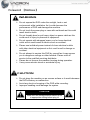
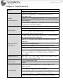
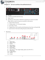
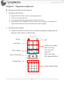
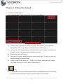
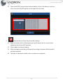
1
16CH NVR User Manual 2013 AUG V1.0 Notice before use This authorization agreement of client’s software/hardware is legally effective to you(individual or single machine) and our company. This agreement covers components of software/hardware, media, print, online publication and electronic files. All the application through installation, duplication or the other way must be based on this agreement. If you disagree with the terms of this agreement, please don’t install or use this product. This product is protected by copyright law, international copyright treaties and other international property laws and treaties. Please note this product authorizes to you, not sold. Through the software/hardware license code on the license certificate indicates you have got the permit of use. Copyright The company owns all the headers, including but not subject to the copyright, software/hardware products and any duplicates. The company reserves all the rights not expressed clearly. Unsecure notes The company clearly denies warrantee repairmen of any products. Unsecure of warrantee for any kind of expressed or implied, including any documents and software products of no limit, implied warrantee repairmen or marketability, suitable for specific usage or non-infringement. Terms and Conditions The overall risk, is that arising out of the use or performance of software and hardware products. This product will be informed, such as when it is used with certain device or other hardware, may enable you to carry out surveillance and data processing, which may be subject to or in violation of applicable law, which includes but is not limited to data privacy, and criminal law. Please check your use to comply with applicable laws is the responsibility of users themselves. Limitation of liability The provision of this paragraph is in effect to the maximum extent permitted by applicable law. In any situation Xia, VACRON or its dealer assumed any special, and accidentally of, and indirect of, and or any indirect loss (including but not limited to business profits loss, and business interrupted, and commercial information loss, and or any other money loss of compensation) due to using or cannot using of software products or provides or failed provides appropriate of support, even we of company has is informed this class damage of possibilities. If there is no willful misconduct or gross negligence, under any provision of this agreement, VACRON total liability, shall be limited to the amount actually paid. Other conventions (A) Prohibition of reverse engineering, decompilation, splitting or rescind the contract within the scope allowed by the applicable law cannot be waived by, as well as any software and hardware components of the product. (B) As long as the recipient agrees to the terms of this agreement, you may permanently transfer rights of use of this product. Closing remarks Without prejudice to any other rights, the company may terminate this license agreement. If you fail to comply with its terms and conditions, in which case you must destroy all copies of the software product. CONTENTS Foreword 【Notices】 ............................................................................................................................. 1 Chapter 1 【Specifications】 ................................................................................................................ 2 Chapter 2 【Front and Rear Panel Illustration】 ........................................................................... 4 1. Front Panel ........................................................................................................... 4 2. Rear Panel ............................................................................................................. 4 Chapter 3 【Hard Drive Installation】 ............................................................................................... 5 Chapter 4 【Hardware Installation】 ................................................................................................. 5 Chapter 5 【Operation Options】 ...................................................................................................... 6 1. Operating with a Mouse ................................................................................. 6 2. Operating with a Remote ............................................................................... 6 Chapter 6 【Operation Setup】 .......................................................................................................... 7 1. Live View and Operation ................................................................................ 7 2. Log .......................................................................................................................... 7 3. Manual Record (One Step Quick Recording) .......................................... 8 4. Setup ...................................................................................................................... 9 5. Playback ..............................................................................................................24 6. Previous and Next and Previous Page.....................................................25 7. Display Mode ....................................................................................................26 Chapter 7 【Advanced Features】 .................................................................................................27 Foreword 【Notices】 WARNING Do not expose the DVR under the sunlight, heat or wet environment while installation. As it could decrease the performance of DVR and damage the machine. Do not touch the power plug or case with wet hands as this could result electric shock. Do not forcedly bend or put heavy object on power cable as this could result in injury to personal or equipment. Do not operate with damaged power cord or loose electrical outlet as this could result in electric shock or accident. Please use individual power instead of share electrical outlets with other electrical equipment as this could result in damage or accident. Do not attempt to service this DVR by yourself as it may expose you to dangerous voltage or other hazards. Please refer all service to the qualified servicing distributor. Please do not remove the machine housing during operation. It may cause electric shock or accidental injury. CAUTION Do not place the machine on an uneven surface or it would decrease the DVR efficiency or malfunction. Avoid any shock or bumping of the DVR while recording. Improper handling could damage the system. CAUTION Make sure the voltage selector switch is set to appropriate setting before plug in! 1 Chapter 1【Specifications】 System CPU: TI SoC Operating system:Linux Build in SATA interface x 4,compatible SATA/SATAII HDD( Max. 3TB) Storage Support E-SATA interface and External E-SATA RAID function Device/Interface HDD Caddy x1 DVD burner x1(Optional) (DVG RW / DVD ±R;DVD burner occupied one interface of SATA) 35 operating buttons on Front panel / shuttle play controller User Interface NVR IR remote control x1 RS-232 x1 –support SMS sending device , SMS generate automatically when Alarm activated 3 Video outputs: HD output x2 and VGA x1 ; The alternatives are HD1 and VGA;HD2 is reserved. USB 2.0 x2 – connect to an external USB devices (mouse or USB flash) Video And Other Alarm OUT x4 / Alarm IN x16 I/O Interface Headphones (speakers) sound output x1 (left and right) Microphone audio input jack x1 (left and right) Ethernet x2 – 10/100/1000 (IEEE 802.3 Type 10Base-T / IEEE 802.3u Type 100Base-TX / IEEE 802.3ab Type 1000Base-T); Auto-MDIX. Network Protocol Ipv4 / ARP / TCP / UDP / ICMP / DHCP / NTP / DDNS / SMTP / FTP / HTTP / RTP / RTSP / RTCP Video Format H.264 compression format E-Map Real-time Live View capable 16CH VGA @30fps or 4CH 1080P @23fps Live / Playback 4-CH 1080P @23fps Synchronous Playback Recording Query: Time search, Event search (IP CAM displacement, Alarm I / O triggered alarm notification) Playback speed/ slow forward / fast forward in 5 different 2 speed, Play Frame by Frame mode (forward or backward) Pentaplex operation: Live/ Record/ Playback Support e-mail / SMS / Mobile App message notifications Event Notification Event Notification : Alarm I / O trigger, Motion detection, Video loss, HDD error Constant recording Schedule recording Alarm triggered recording (include motion detection recording): Complete event video reserved Recording Mode 10 seconds before and 60 minutes after event taken place. Schedule alarm triggered recording (include motion detection recording): Complete event video reserved 10 seconds before and 60 minutes after event taken place. Manual recording Only recording without live (depending on user authority) Backup Management Video output format: AVI The dump media directly burn to CD / DVD (optional) USB mobile storage device or remote NAS Remote Client software; live, playback set up by PC (remote side) Authorization: Maximum 10 group accounts, Hierarchical System authority Management Support 3 users log on by Client-side software or browser. Systems operation records, record login time, IP and selected video. Browser: MS IE7-IE9 / Fire Fox / Safari / Chrome Support Equipment Power Support megapixel IP Camera video Support CCTV camera video via Video Server. DC12V / 8.33A ( accessory 110V-240V 2.5A / DC12V 8.33A ADAPTER x 1) Operating Temperature 0-45 ℃ 3 Chapter 2 【Front and Rear Panel Illustration】 1. Front Panel A) USB slot B) Lockable removable hard drive tray. C) Power switch D) Operating on front panel is identical to operating on remote controller. Please refer to section of remote controller for instructions. 1) Single channel buttons 2) Display mode: 4, 9, 16 channel viewing 3) Arrow keys / Enter 4) Playback keys: fast forward/rewind/play/pause/stop keys, and jog shuttle 5) 2. Quick buttons: Record/Live/Play/Sequence/Next/Screen. Rear Panel 1) 2) 3) 4) 5) 6) 7) 8) 9) 10) 11) 12) Alarm Input Alarm Output RS-232 XGA Output Video Output Audio Input Audio Output HD Output x 2 (For single display, please use HD OUT 1) LAN x2 port E-SATA Output USB 2.0 DC12V 4 Chapter 3 【Hard Drive Installation】 Please install at least one hard drive before starting record video. 1. Power off the NVR 2. Insert the removable HDD tray to the removable HDD slot and close the HDD panel. 3. Lock up the HDD panel to prevent unauthorized removal of HDD. 4. For the use of large-capacity storage space (E-SATA), connect an E-SATA disk array to E-SATA input located on the back panel. Chapter 4 【Hardware Installation】 1. Connect network cameras to a network switch with network cables. CAT6 network cable or better is highly recommended. When connect network switch to the NVR, make sure the network LED indicator is lid up. (The network connection of the NVR is designed to be used with dedicated IP connectivity. (For general internet setup and knowledge, please refer to network setup). 2. For usage of the DC 12V power adaptor and cable, please refer to diagram of the rear panel. 3. The NVR will power up and display live viewing automatically when power is connected. Please refer to live viewing for more info. 5 Chapter 5 【Operation Options】 Operating with a Mouse and a Remote 1. Operating with a Mouse 1) Right click at Live View screen to open system menu. 2) Click to enter selected item. 3) Scroll mouse wheel to change value at drop down menu. 4) Press [APPLY ALL CHANNEL] button to apply current settings to all channels or right click at edit box to enter characters over screen keypad. 2. Operating with a Remote 1) Operation of remote controller and front panel are identical. Please refer the diagram of the remote controller below: Record LOG PLAY BACK AUDIO: Record Audio PREV: Prev. Page LIVE: Live View PTZ Controller ID:NVR ID NEXT: Next Page Enter / Arrows Keys SEQ: Sequential Mode Display Mode Single Channel Mode 6 Chapter 6 【Operation Setup】 1. Live View and Operation 1.1 Live view display after start up as diagram shown below. 1.2 Left and then right click any place on screen, menu bars on top-right and bottom-left will pop up. Right click again to close menu bars. 1.3 Viewing channel display may relocate freely on screen. Simply click and hold the left button and drag to desired display channel. 1.4 System time and HDD status. 1.5 Double click on time display to zoom-in and zoom-out. To move it, click and hold and drag to desire location. 1.6 Please format HDD before use. If HDD is not found, please format it again. To format HDD, go to SETUP and STORAGE menu. 2. Log 2.1 It generates event log of the system that are considered abnormal. Users may click and retrieve the event log on a specific date on the calendar. 7 2.2 Open the EVENT page as figure shown below, click on the date you wish to view, the event log will appear on the right side of screen. 3. Manual Record (One Step Quick Recording) 3.1 Right click then click on [Emergency] at quick launch bar to record video streaming sent from all IP cameras. 3.2 Click it again to stop recording. 3.3 After emergency recording, all manual recording channels will be blocked with blue squares. 3.4 The data is indicated in black color on time bar in playback. 8 4. Setup 4.1 Right click on live view screen to bring up Quick Launch Bar. Click [SETUP] to bring up SETUP menu as shown below. DISPLAY 1) The default setting of video display is HD and VGA resolution. Click on drop down menu of resolution to choose resolution setup. The maximum video resolution is 1080P. 2) If resolution is set at HD during dual-monitor display, one monitor may 9 be a spot monitor. 3) Click on [SAVE] to save and exit. CAMERA Setup 1) Choose the type of network camera. 2) Enable connection and display. Enter title of the camera, IP address, port, login name, and password. (Default login name: admin, password: admin) 10 3) The parameters of selected cameras must setup correctly. It includes stream types: main and sub stream; bitrate types: VBR (variable bitrate) and CBR (constant bitrate); frame rate, and bitrate. Click [apply all channel] to apply identical parameters to all cameras. 4) Color of cameras can be adjusted including brightness, contrast and saturation. Click [apply all channel] to apply identical parameters to all cameras 11 5) Select [ENABLE] to enable motion detection. Click [apply all channel] to apply identical parameters to all cameras. (Note: Motion detection must enable on camera end.) 12 Search 1) Enter SEARCH menu, click [START], the system will generate a list of cameras that are found and connected to the network. The number of cameras that are found in the network is located on the top-right corner. (Note: This does not mean the cameras are connected to the NVR). 2) Important! Click [STOP] to stop searching for cameras and proceed to next step. 3) Check all IP addresses of network cameras and make sure there is no duplication. 4) Set new IP addresses manually. 5) If the search to 16 or more IP CAM, select Next. 6) the user selects IP CAM Meanwhile, in the lower right corner will remind the user has selected IP CAM quantity. 13 7) Point the cursor and click the IP address under new IP that needs to be changed. On-screen keyboard will popup in the screen. Click again to close on-screen keyboard. 8) Make sure all NEW IP addresses are correct. Mark the cameras that will connect to the NVR. Click [SELECT ALL IPCAM] on top-left corner to apply to all cameras. (Note: the maximum number of cameras supported is 16 units). Click [APPLY] when ready to connect. Caution! IP addresses of NVR and cameras cannot be the same. Default IP address of NVR is 192.168.1.69. 14 9) Please allow the system apx. 20 seconds to connect the selected cameras. All channels that are connected successfully will show images, MAC addresses, and ip addresses. Otherwise, the channel will show blank. Click [STOP] when done. RECOR Record Setup 1) Click [ENABLE] to enable video and audio record. 2) Click [ENABLE] to enable pre-record (PREV REC) and post-record (POST 15 REC) and duration of alarm event. 3) Click [SELECT ALL IPCAM] to apply to all cameras. 4) Click [SAVE] to save and exit record setting. Schedule Record 1) Each camera can be set with its own schedule record individually. 2) Click record event type drop down list and select record event type. Then click on the cells to schedule record time of the day. Each cell represents an hour. 3) Click [SELECT ALL IPCAM] to apply to all cameras. 4) Click [SAVE] to save and exit schedule record setting. 16 EVENT Event Notification 1) Click [ENABLE] to enable email notification of an event. Server mail, server port, from email, login name, login password, and to mail must enter correctly as well as interval time between two email notifications. 2) Click [ENABLE] to enable send SMS function. Enter the phone number of the recipient and interval time between two SMS phone notification. Note: SMS phone notification must install SMS machine. Click [SAVE] to save and exit setting. 17 3) Sensor device must install and connect to ALARM IN. The NVR supports up to 16 sensors. Click [ENABLE] and select NO (normal open) or NC (normal close). When sensor triggers, email, SMS phone, and ALARM OUT (1~4) notifications can be sent out simultaneously. Click [SAVE] to save and exit sensor setting. 4) ALARM OUT device must install. The NVR supports up to 4 ALARM OUT devices. It may be triggered by motion detection, signal loss, or sensor detection (1~16). Click [ENABLE] to enable ALARM OUT function. Set device name, type: NO (normal open) or NC (normal close) and duration time. Click [SAVE] to save and exit ALARM OUT setting. 18 MOTION 1) MOTION : click [MOTION] to get to MOTION page. Click on the cell to mark types of notification: email, SMS phone, and alarm 1 to 4. 2) VIDEO LOSS : click [VIDEO LOSS] to get to VIDEO LOSS page. Click on the cell to mark types of notification: email, SMS phone, and alarm 1 to 4. 3) SENSOR : click [SENSOR] to get to SENSOR page. Click on the cell to mark types of notification: email, SMS phone, and alarm 1 to 4. 4) Click [SAVE] to save and exit setting. AUDIO 1) Click [ENABLE] to enable audio. 2) Click VOLUME drop down list and select volume level. 3) Select AIC or HD OUT 1 as audio out device. 4) Click [SAVE] to save and exit audio out setting. 19 STORAGE 1) Click [RECYCLE] for continuous recording and overwrite the old data on storage device. Click [ONCE] to record once and stop recording when storage is full. 2) The hard drives must be formatted sequentially before use to help establish overall storage space. 3) New hard drive installed must be formatted by the NVR before use. BACKUP 1) Insert USB flash memory device to USB slot on the NVR. 2) Select the camera from the list on left you wish to backup. Select the date on the calendar. 3) Use up / down arrows to change start and end times. 4) Set backup file type to AVI and device. 5) Click [BACKUP START] to begin backup. 20 SYSTEM INFORMATION 1) Current firmware and hardware versions. 2) MAC addresses and build date/time. 3) UBOOT and KERNAL versions and time released. 21 NETWORK 1) Two Ethernet available: Ethernet 0 and 1. 2) Click ip address cell to get the on-screen keyboard. Change ip address if needed. Click again to close the on-screen keyboard. 3) Select STATIC or DHCP. 4) Click [SAVE] to save and exit network setup. SETUP 1) Setup current data/time. Point the cursor on the date/time and use the wheel on the mouse to change the date/time. Click [APPLY TIME] to save the changes. 2) Select language. System must reboot to change to the set language. 3) SYNC IPCAM PARA:Can set whether to start synchronization,you can configure this interval. 4) Can be set whether to open the map function. 5) Firmware update: Save updated firmware on a USB and insert it to the USB slot on the front panel. Click [USB UPDATE]. (Note: the updated firmware must save on top layer on the USB). 6) Config Initialize: Click [CONFIG INIT] to reset the system to factory default setting. 7) System Reboot: Click [REBOOT] to reboot the system. 22 PASSWORD 1) Click [ENABLE] to enable password setting. Administrator has highest authority of operation. Administrator can authorize USERs different features by enabling/disabling playback, setup, and PTZ. Enter user name, password, and confirm password. Click [SAVE] to save and exit setting. 23 5. Playback 5.1 Operations of Playback 1) Click to go back to 16 channel live viewing. 2) Click to go back to previous set of four channel viewing. 3) Click to go to next set of four channel viewing. 4) Click to single channel viewing. 5) Click to four channel viewing. 6) Click to Arbitrary choice four channel viewing. 5.2 Search 1) Find the month and date on the calendar to view. Use the left/right arrows on top-left and right of the calendar to change the month and year. The dates that are red color represent there is data stored. 2) After selecting the date to view, click on the specific time of the day to view. 3) Each cell represents time of recording. It can be set from one to four minutes (default) per cell. (The unit indicator on top-left corner within the playback control screen shows recording time per cell). Click to enlarge the time bar. 4) After enlarging the time bar, it may not display the entire day in screen. Click to move to the specific time to view. 5) Click to move to the specific time to view. 24 6) Use the playback control buttons as chart below after finding the specific time to view. : Play : Stop : Pause : Revere (max. 32X) : Forward (max. 32X) : Reverse Playback by Frame : Forward Playback by Frame 6. Previous and Next and Previous Page 6.1 Click to go to previous / next four channel viewing. 6.2 Click the yellow arrows on center point of left and right side of screen to go to previous/next four channel viewing. 25 7. Display Mode 7.1 Click for 1, 4, 9, or 16 channel viewing 26 Chapter 7 1. 【Advanced Features】 Quick Adjustment Viewing Channel Layout. 1.1 The viewing channels are displayed in the order of IP address (e.g. xxx.xxx.xxx.001 is displayed before xxx.xxx.xxx.002). 1.2 Two viewing channels may be swapped viewing squares. 1.3 Click, hold, (the edge of the viewing channel turns green), drag and drop the channel to the desired position. 2 Quick Camera Info Display and Modification 2.1 Click the viewing channel for on-screen keyboard. 2.2 Right click on the cell to change parameter of the camera including camera name, ip address, and port. It also allows you to copy, paste, and delete. 27 3 Quick Search for IP Address and Name Change 3.1 Click top-left corner of the camera. 3.2 The parameter of the camera will appear on screen. Click on the cell for on-screen keyboard. 3.3 This does not mean change the setting on actual camera. This feature is only for quick viewing of already-known cameras that has been setup properly. 3.4 If changing ip address of a camera is needed, go to camera setup. Right click to close on-screen keyboard. 4. Quick Selection of Viewing Channels 4.1 Press and hold the left button to select specific channels to view. 4.2 he edges of the channel will turn green as shown below. Then click additional three channels if desired. (Maximum of 4 channels allowed). 4.3 After selecting the 4th channel, the live view changes to 4 –channel viewing automatically. 4.4 The sequence of channels is based on the order of channel selecting. Right click to finish and back to the original live viewing setting. 28 5. Zoom-In on Single Channel Display 5.1 Double click a channel, the live viewing will change to single channel viewing. 5.2 The yellow arrow for changing channel is located on the center of left/right side of the channel. Click left arrow for previous channel and right arrow for next channel. 5.3 hold, and mark the spot to zoom-in as shown below. 5.4 Release the left button on the mouse to see the zoomed-in area. Press, hold and maneuver the zoomed-in area. 5.5 This allows users to monitor the area easier. 5.6 Click right button to end zoom-in function. 29 6. Firmware Upgrade 6.1 Save new firmware on a USB flash memory or on a PC. 6.2 Enter the ip address of the NVR via network browser. (Default NVR IP address is 192.168.1.69). 6.3 Click [Firmware Upgrade]. Click [Browse] to locate new firmware on PC. 6.4 Click [upgrade] to begin firmware upgrade. Pay attention on the timer on screen. 6.5 When complete, the system will reboot and show live viewing automatically. The original setting of parameter remains unchanged. 6.6 If new firmware is saved on a USB flash memory, click [USB UPDATE] to begin firmware upgrade. 30 7. PTZ 7.1 Click top-left corner of a camera to bring up parameter ofcamera info. 7.2 Click PTZ icon on top-right corner for on-screen directional control panel. 7.3 On-screen PTZ directional control panel stays on screen during live viewing. 31 8. Remote Monitoring and Playback 8.1 To live view remotely on NK700, enter its IP address on IE to connect. 8.2 Click on the channels located on left side of screen to connect and view. 8.3 To playback remotely, click on the channels located on left side of screen. The time bar and calendar will appear on bottom of screen. 8.4 Click on the specific time you wish to view. The maximum number and resolution to view simultaneously is 4 channels on 1080P. Operating keys such as fast forward is located on bottom-right side of screen. 32 For More Information Please check VACRON Website http://www.vacron.com Made in Taiwan