1
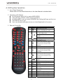
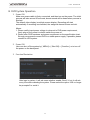
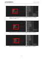
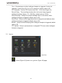
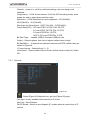
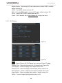
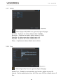
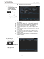
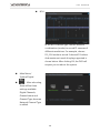
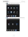
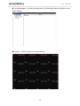
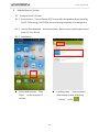
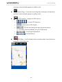
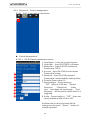
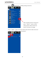
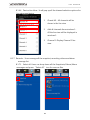
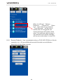
User Manual VDH-DX 2013 OCT V1.3 H-DX User Manual WARNING Do not expose the DVR under the sunlight, heat or wet environment while installation. As it could decrease the performance of DVR and damage the machine. Do not touch the power plug or case with wet hands as this could result electric shock. Do not forcedly bend or put heavy object on power cable as this could result in injury to personal or equipment. Do not operate with damaged power cord or loose electrical outlet as this could result in electric shock or accident. Please use individual power instead of share electrical outlets with other electrical equipment as this could result in damage or accident. Do not attempt to service this DVR by yourself as it may expose you to dangerous voltage or other hazards. Please refer all service to the qualified servicing distributor. Please do not remove the machine housing during operation. It may cause electric shock or accidental injury. CAUTION Do not place the machine on an uneven surface or it would decrease the DVR efficiency or malfunction. Avoid any shock or bumping of the DVR while recording. Improper handling could damage the system. CAUTION Make sure the voltage selector switch is set to appropriate setting before plug in! H-DX User Manual CONTENTS A. DVR System Operation..................................................................................................................... 1 1. Front Panel Operation .............................................................................................................. 1 2. Operation with Mouse .............................................................................................................. 1 3. Remote Controller ...................................................................................................................... 1 B. DVR System Operation..................................................................................................................... 3 1. Power ON....................................................................................................................................... 3 2. Power ON....................................................................................................................................... 3 3. Function Illustration ................................................................................................................... 3 4. Display Setup................................................................................................................................ 4 5. Main Menu .................................................................................................................................... 7 5.1 Record ..................................................................................................................................... 7 5.1.1 Record Conf .......................................................................................................... 8 5.1.2 PlayBack ................................................................................................................. 9 5.1.3 Backup ................................................................................................................. 12 5.2 Alarm..................................................................................................................................... 13 5.2.1 Motion Detect ................................................................................................... 14 5.2.2 Video Blind ......................................................................................................... 15 5.2.3 Video Loss .......................................................................................................... 16 5.2.4 Alarm Input ........................................................................................................ 18 5.2.5 Alarm Output .................................................................................................... 19 5.2.6 Abnormality ....................................................................................................... 19 5.2.7 Intellingent ......................................................................................................... 20 5.3 System .................................................................................................................................. 21 5.3.1 General ................................................................................................................ 22 5.3.2 Encode ................................................................................................................. 23 5.3.3 Network ............................................................................................................... 24 5.3.4 NetService .......................................................................................................... 25 5.3.5 GUI Display ......................................................................................................... 26 5.3.6 PTZ Config .......................................................................................................... 27 5.3.7 RS232.................................................................................................................... 28 i H-DX User Manual 5.3.8 Tour ....................................................................................................................... 28 5.3.9 Spot Set ............................................................................................................... 29 5.3.10 Digital ................................................................................................................ 30 5.4 Advanced ............................................................................................................................ 58 5.4.1 HDD Manage..................................................................................................... 58 5.4.2 Account ............................................................................................................... 59 5.4.3 Online User ........................................................................................................ 59 5.4.4 Output Adjust ................................................................................................... 60 5.4.5 AutoMaintain .................................................................................................... 60 5.4.6 Restore ................................................................................................................. 61 5.4.7 Upgrade .............................................................................................................. 61 5.4.8 Device Info.......................................................................................................... 62 5.4.9 Import/Export ................................................................................................... 62 5.5 Info ......................................................................................................................................... 63 5.5.1 HDD Info ............................................................................................................. 63 5.5.2 BPS......................................................................................................................... 64 5.5.3 LOG ....................................................................................................................... 64 5.5.4 Version ................................................................................................................. 65 5.6 Logout .................................................................................................................................. 66 6. NET Surveillance WEB IE........................................................................................................ 67 7. Login Cloud service via IE browser.................................................................................... 73 8. Mobile Monitor System......................................................................................................... 74 8.1 Android Vacron Viewer ............................................................................................... 74 8.2 iOS VacronViewer .......................................................................................................... 88 ii H-DX User Manual A. DVR System Operation 1. Front Panel Operation Please refer to Front Panel Instruction in the User Manual in attached disk. 2. Operation with Mouse In LIVE mode: Right click to enter MAIN MENU Click LEFT Key to enter /select menu operation. In MAIN MENU, user can enter SUBNENU by clicking left keys on the icon. Click RIGHT key to quit User can change setting by mouse or virtual keyboard in the menu. 3. Remote Controller 1 2 REC LOCK 3 4 5 6 7 █ 8 9 10 11 INFO 12 SEQ 13 RESET 14 SEARCH 15 PTZ 16 17 18 19 Z+ ZF+ F- 1 Enter RECORDING MODE Key Lock / Log-out Previous Page; available by Pause of PALYBACK mode Enter PLAY and BACKUP mode in LIVE VIEW mode. PLAY/ PAUSE in PLAYBACK mode PLAY/ PAUSE Next Page; available by Pause of PALYBACK mode Under the playback mode, there are 4 choices for the speed. Choose your choice to fast rewind. STOP; in PLAYBACK mode Under the playback mode, there are 4 choices for the speed. Choose your choice to fast forward. Under the playback mode, there are 4 choices for the speed. Choose your choice to slow forward. In Playback mode: Jump to next video System Version Display Sequence display (in Live-view mode) Reset all siren information Enter PLAY BACK user control interface Enter PTZ camera user control interface PTZ camera; Zoon IN PTZ camera; Zoom OUT PTZ camera: Focus IN PTZ camera: Focus OUT H-DX 20 21 ID ENTER 22 23 24 25 26 27 MENU ESC 28 29 30 User Manual Set ID code to control different DVR Enter / Confirm UI mode: Upper Option Live view mode: control video display page in single channel, 4, 8, 9 split display. PTZ control mode: UP UI mode: Downward Option Live view mode: control video display page in single channel, 4, 8, 9 split display. PTZ control mode: Downward UI mode: LEFT Option 1/4/8/9 display switch in LIVE mode. In PTZ control mode: Left UI mode: RIGHT Option 1/4/8/9 display switch in LIVE mode. In PTZ control mode: Right In LIVE mode: To enter operation Menu. Exit operation of single channel (LIVE or Playback mode) 4-split video display, press this bottom again to show next set 4-split video. (LIVE or Playback mode) 8-split video display, press this bottom again to show next set 8-split video. 1-8、9-16 (LIVE or Playback mode) 9-split video display, press this bottom again to show next set 9-split video. 1-9、8-16 16 Split screen 31 32 1~10(0) 33 11~16 In LIVEVIEW or PLAYBACK mode to show chosen video CH1~CH10; Number keys. In LIVEVIEW or PLAYBACK mode to show chosen video CH11~CH16 Note:There are many DVR equipments in the same place, the remote control first need to select a device, according to the DVR ID. So, should give each DVR device to define a unique device number (DVR ID). Otherwise, the remote control operation may be playing a role for multiple devices with the same DVR ID number at the same time. Set remote control of DVR Press 【DVR】 and then enter the DVR ID you want to operate, default DVR ID code is 000. User can set DVR ID by [Main Menu] > [ Basic] > [ System]. DVR IDcan be set between 001~998 (ID should be 3 digits ), then press【ENTER】to confirm the settings. Usercan operate different DVRs after doing the settings. 2 H-DX User Manual B. DVR System Operation 1. Power ON Make sure power cable is firmly connected, and then turn on the power. The initial process will take around 20 seconds, buzzer sound will be heard when process is finished. The default video display is multiple screen display. Recording will start automatically if recording is scheduled, the assigned channel shows red-dot. Memo: 1. Please vertify imput power voltage is coherent to DVR power requirement, firmly plug on the power line befor switch the power on. 2. Please refer DVR hardware and power requirement on the specification chart. Strongly recommend connect DVR to a stable power supply, if possible, please connect to UPS system. 2. Power ON User can shut off the system by [ MENU] > [ Shut Off] > [ Comfirm], or to turn off the power on the back panel. 3. Function Illustration After logo in system, it will ask users whether enable Cloud? If not, it will ask every time after rebooting the system. Please select the option “Will no longer be prompted” to avoid it. 3 H-DX User Manual In the multi- screen, right click the mouse, and a Quick-menu pop up. Select Main Menu or rest functions, key in Account ID & Password to login. Default Value of Account ID: admin, Password: blank. 4. Display Setup Select View 1 for monitoring Single screen, optional CAM01~16 single screen. 4 H-DX User Manual Select View 4 for monitoring 4 screens, optional CAM1~4 ,4, CAM5~8, CAM9~12, CAM13~16. Select View 8 for monitoring 8 screens, optional CAM1~8, CAM9~16. Select View 9 for monitoring 9 screens, optional CAM1~9, CAM8~16. 5 H-DX Select View 16 for monitoring 16 screens, 16 split screen. 6 User Manual H-DX 5. User Manual Main Menu (Figure 1) (Figure 2) Right click the mouse, select Main Menu and it will pop out, as (Figure 1) & (Figure 2). 5.1 Record (Figure 3) :Select (Figure 2) Record icon, pop out (Figure 3) page. 7 H-DX 5.1.1 User Manual Record Conf (Figure 4) : Select (Figure 3) Record Conf. icon, pop out (Figure 4) page. Channel:Scroll down window to Set the settings for 1Ch or all Ch, default value is channel 1. Redundancy:HDD RAID, when install the 2nd HDD, it is able to activate the disk mirror function. It simultaneously uploads the records to another HDD. Default value is Off. Length:Adjust the time period of recording, at least 1 Min, Max 120 Min. Default value is 60 Min. Prerecord: Mode:3 options: Schedule, Manual & Stop. Schedule mode: select requested days first, and then select recording mode & time, total 4 periods of time to choose; Manual mode: must complete the settings before recording; Stop mode: no recording at all; default value is settings. 8 H-DX User Manual 5.1.2 PlayBack c a b (Figure 5) (Figure 6) :Select (Figure 3) PlayBack icon, pop out (Figure 5) page. 9 H-DX User Manual a). Play select date & channels, click play button to playback. Pause Pause the video Back forward Rewind Play Video Stop Slow playback Fast rewind Fast forward, Click pause rewind button Stop video playback 4 speed options: 1X、2X、3X、4X. Return to normal speed, just click play button once again. 4 speed options: 1X、2X、3X、4X. Return to normal speed, just click play button once again. 4 speed options: 1X、2X、3X、4X. Return to normal speed, just click play button once again. rewind the image frame by frame. Click pause playback button playback the image frame by frame. Previous file button back to last hour file and playback. Next file button go to next hour file and playback. Click repeat button icon becomes to Click full screen button Click scissors button While using scissors button , repeat same file. enlarge the image. Click one more time back to normal. let icon becomes to period of time, and click backup the file. , select requested one more time to this function will be activated. Save modified file to USB (Flash disk). 10 H-DX User Manual b). Playback selected options; default value is select all. Select this function, click pause button or others to make it active; without selecting this function, only single Channel works. Select more accurate timing for playback, such as 24hr, 2 hr, 1 hr, 30 min; default value is 24 hr. c). Select a date to get into time table page, like (Figure 6), and click return to date searching page. Right click mouse, a dialogue pops out. UpWindow: Click to return previous layer, and back to Record page. Stop playback:Click to stop, select “Stop playback” to stop playing. Full screen display: Click “Full screen” to enlarge images to maximum, and then right click mouse to close full screen. Single screen:Select single screen, choose 1~16 Ch to playback. Four screens:Available options Ch1~4, Ch 5~8, Ch 9~12, Ch 13~16 to playback. Nine screens:Available options Ch1~9, Ch 8~16. Sixteen screens: Play back at all 16 Ch. 11 H-DX 5.1.3 User Manual Backup : Select (Figure 3) Backup icon, get into (Figure 6) page. (Figure 6) (Figure 7) (Figure 8) :Plug in USB storage device, click detect to search USB storage which will be shown in window, like (Figure 6). :Select backup icon to get into (Figure 7) page. 12 H-DX User Manual Type:All、External alarm、Motion detection、All alarm、Manual、Normal; default value is All channels. Channel:select which channels need to Backup, optional from Ch1~16; default value is Ch1. Start Time:select what time need to start backup. End Time:select what time to end backup. Remove:Remove selected files. Add:Add selected types or channels. Backup format:select H264 or AVI; default value is H264. :Select Burning icon to get into (Figure 8) page, enable to save any one Channel’s record into an USB storage device Synchronously. :Format selected USB storage device. :While backup, click stop icon to stop backup. 5.2 Alarm : Select (Figure 2) Alarm icon, get into (Figure 9) Page. (Figure10) (Figure 9) 13 H-DX (Figure 11) 5.2.1 User Manual (Figure 12) Motion Detect : Select (Figure 9) Motion Detect icon, get into (Figure 10) page. Channel:setup ch1~ ch 16 for individual settings, also can setup for all channels. Enable:Select to setup for the Motion Detect functions; default value is Off. Sensitivity:Set the sensitivity level, from lowest、lower、middle、higher、much higher、highest, 6 options. Default value is middle. Region: Select triggered area, as (Figure 11); default value is all area. Period:setup the alarm settings from Monday to Sunday, Any 4 days. Interval:Time between each trigger, 1 ~600 Sec. Alarm Output:According to the settings to trigger alarm output; default value is Off. Delay: A time period to record after triggering motion detect alarm, option: 0 ~ 3000 Sec; default value is 10 Sec. Channel Recording:Select which channel to record after motion detect is triggered; default value is Off. Tour:Channel pops out after alarm is triggered. If select all channels, it jumps from Ch 1 to ch16 in sequence; default value is Off. PTZ Activation:Setup the PTZ function from Ch1 ~ Ch16, as (Figure 12). Record delay:The recording duration after the buzzer being triggered. Option: 0 ~ 3000 Sec; default value is 10 Sec. Show message:Setup for a prompt message show on the screen when motion alarm is triggered; default value is Off. 14 H-DX User Manual Send Email:Setup to send triggered photos to assigned email address when motion alarm is triggered; default value is Off. Buzzer:Setup for buzzer beeping after motion alarm is triggered; default value is off. FTP Upload:Setup to upload photos to assigned FTP server when motion alarm is triggered. 5.2.2 Video Blind (Figure 13) : Select (Figure 9) Video Blind icon, get into (Figure 13) page. Channel:setup ch1~ ch 16 for individual settings, also can setup for all channels. Enable:Select to setup for the Video Blind functions; default value is Off. Sensitivity:Set the sensitivity level, from lowest、lower、middle、higher、much higher、highest, 6 options. Default value is middle. Period::setup the Video Blind from Monday to Sunday, Any 4 days. Alarm Output:According to the settings to trigger Video Blind output; default value is Off. 15 H-DX User Manual Delay: A time period to record after triggering Video Blind, option: 10 ~ 3000 Sec; default value is 10 Sec. Record Channel:select which channel to record after Video Blind is triggered; default value is Off. Tour:Channel pops out after Video Blind is triggered. If select all channels, it jumps from Ch 1 to ch16 in sequence; default value is Off.. PTZ Activation:Set the PTZ function from Ch1 ~ Ch16, like (Figure 12). Record Delay:The recording duration after the buzzer being triggered Video Blind. Option: 10 ~ 3000 Sec; default value is 10 Sec. Show message:Setup for a prompt message show on the screen when Video Blind is triggered; default value is Off. Send Email:Setup to send triggered photos to assigned email address when Video Blind is triggered; default value is Off. Buzzer:Setup for buzzer beeping after Video Blind is triggered; default value is Off. FTP Upload:Setup to upload photos to assigned FTP server when Video Blind is triggered. 5.2.3 Video Loss (Figure 14) 16 H-DX User Manual :Select (Figure 9) Video loss icon, get into (Figure 14) page. Channel:setup ch1~ ch 16 for individual settings, also can setup for all channels. Enable:Select to setup for the Video Loss functions; default value is Off. Period:setup the Video Loss from Monday to Sunday, Any 4 days. Alarm Output:According to the settings to trigger Video Loss output; default value is Off. Delay: A time period to record after triggering Video Loss, option: 10 ~ 3000 Sec; default value is 10 Sec. Record Channel:select which channel to record after Video Loss is triggered; default value is Off. Tour:Channel pops out after Video Loss is triggered. If select all channels, it jumps from Ch 1 to ch16 in sequence; default value is Off.. PTZ Activation:Set the PTZ function from Ch1 ~ Ch16, like (Figure 12). Record Delay:The recording duration after the buzzer being triggered Video Loss. Option: 10 ~ 3000 Sec; default value is 10 Sec. Show message:Setup for a prompt message show on the screen when Video Loss is triggered; default value is Off. Send Email:Setup to send triggered photos to assigned email address when Video Loss is triggered; default value is Off. Buzzer:Setup for buzzer beeping after Video Loss is triggered; default value is Off. FTP Upload:Setup to upload photos to assigned FTP server when Video Loss is triggered. 17 H-DX User Manual 5.2.4 Alarm Input (Figure 15) :Select (Figure 9) Alarm Input icon, get into (Figure 15) page. Channel:setup ch1~ ch 16 for individual settings, also can setup for all channels. Enable:Select to setup for the Alarm Input funtions; default value is Off. Type: Setup Normal open or Normal close; default value is Off. Period:setup the Alarm Input from Monday to Sunday, Any 4 days. Alarm Output:According to the settings to trigger Alarm Input; default value is Off. Delay: A time period to record after triggering Alarm Input, option: 10 ~ 3000 Sec; default value is 10 Sec. Record Channel:select which channel to record after Alarm Input is triggered; default value is Off. Tour:Channel pops out after Alarm Input is triggered. If select all channels, it jumps from Ch 1 to ch16 in sequence; default value is Off. PTZ Activation:Set the PTZ function from Ch1 ~ Ch16, like (Figure 12). Record Delay:The recording duration after the buzzer being triggered Alarm Input. Option: 10 ~ 3000 Sec; default value is 10 Sec. Show message:Setup for a prompt message show on the screen when Alarm Input is triggered; default value is Off. Send Email:Setup to send triggered photos to assigned email address when Alarm Input is triggered; default value is Off. Buzzer:Setup for buzzer beeping after Alarm Input is triggered; default value is Off. 18 H-DX User Manual FTP Upload:Setup to upload photos to assigned FTP server when Alarm Input is triggered. 5.2.5 Alarm Output (Figure 16) :Select (Figure 9) Alarm Output icon, get into (Figure 16) page. 5.2.6 Abnormality (Figure 17) :Select (Figure 9) Abnormality icon, get into (Figure 17) page. Event Type:Optional: No Disk, Disk Error, Disk No Space, Net Disconnection, IP conflict…etc. Enable:Select to setup for the Abnormality function; default value is Off. Show message:Setup for a prompt message show on the screen when Abnormality is triggered; default value is Off. Buzzer:Setup for buzzer beeping after Abnormality is triggered; default value is Off. 19 H-DX 5.2.7 User Manual Intellingent (Figure 18) (Figure 19) :Select (Figure 9) Intelligent Analysis icon, get into (Figure 18) page. Channel:setup ch1~ ch 16 for individual settings, also can setup for all channels. Enable:Select to setup for Intelligent functions; default value is Off. Algorithm:3 options:Perimeter alert, Items care, Video Diagnosis. Rule:click “Set” get into (Figure 19) page, setup whether to Show Traces, Sensitivity: Higher, middle, low. Move scroll bar for Minimum moving distance. Alert way: Cordon & Warning Area. Alarm Output:According to the settings to trigger Intelligent analysis; default value is Off. Delay: A time period to record after triggering Intelligent analysis, option: 10 ~ 3000 Sec; default value is 10 Sec. Record Channel:select which channel to record after Intelligent Analysis is triggered; default value is Off. 20 H-DX User Manual Tour:Channel pops out after Intelligent Analysis is triggered. If select all channels, it jumps from Ch 1 to ch16 in sequence; default value is Off. PTZ Activation:Set the PTZ function from Ch1 ~ Ch16, like (Figure 12). Record Delay:The recording duration after the buzzer being triggered Intelligent Analysis. Option: 10 ~ 3000 Sec; default value is 10 Sec. Show message:Setup for a prompt message show on the screen when Intelligent Analysis is triggered; default value is Off. Send Email:Setup to send triggered photos to assigned email address when Intelligent Analysis is triggered; default value is Off. Buzzer:Setup for buzzer beeping after Intelligent Analysis is triggered; default value is Off. FTP Upload:Setup to upload photos to assigned FTP server when Intelligent Analysis is triggered. 5.3 System (Figure 20) :Select (Figure 2) System icon, get into (Figure 20) page. 21 H-DX 5.3.1 General (Figure 21) (Figure 22) (Figure 23) 22 User Manual H-DX User Manual :Select (Figure 21) General icon, get into (Figure 21) page. System Time:Setup current Year, date & time. Date Format:Time format setup, set up of YYYY/MM/DD, MM/DD/YYYY, DD/MM/YYYY, the default value is YYYY/MM/DD. Date Separator:Options:-./, date presents by selected symbol; The default value is -. Time Format:Set: 24-HOUR or 12-HOUR; The default value is 24-HOUR. Language:There are 28 languages can select. HDD Full:Setup Overwrite HDD or stop writing while HDD is full; The default value is Overwrite. DVR No.:Set DVR No., Options: 0 ~998;The default value is 0. Video Standard:Set Video Standard, NTSC or PAL. Auto Logout:After a period of time without using, it requests to input Password to access Menu, options: 0 ~ 60 Min, 0 means no Password required; default value is 0. Machine Name:Setup the Name of DVR, maximum 32 characters;default value is LocalHost. Daylight Saving Time:Set Day of Week (Figure 22) & Date(Figure 23), it will add 1 hour for assigned time. 5.3.2 Encode (Figure 24) :Select (Figure 20) Encode icon, get into (Figure 24) page. 23 H-DX User Manual Channel:setup ch1~ ch16 for individual settings, also can setup for all channels. Compression:H.264 & extra stream, H.264 for DVR recording model, extra stream for web or smart phone monitor mode. Resolution:H.264 Resolution for device playback : CIF(352x240)、 HD1(704x240)、D1(704x480), Resolution for Extra stream : QCIF(176x120)、CIF(352x240). Frame Rate(FPS):CIF max NTSC: 30 FPS, PAL: 25 FPS; D1 max NTSC: 30 FPS, PAL: 25 FPS; D1 max NTSC/PAL: 15 FPS; QCIF & CIF max NTSC/PAL: 6 FPS. Bit Rate Type: Variable (VBR) & Constant (CBR) bit rate. Quality:Several options, from low to highest; default value is high. Bit Rate(Kb/s): It depends on selected resolution and FPS; default value as shown in Figure 24. 1 Frame Interval:Optional from 2 ~ 12. Video/Audio:Select enable Video & Audio, default value is Video On/ Audio Off. 5.3.3 Network (Figure 25) :Select (Figure 20) Network icon, get into (Figure 25) page. This figure is only available while connect to IP router. Net Card:Wire Netcard. DHCP Enable:Select to auto dispatch IP, unable select is need to key in IP manual. 24 H-DX User Manual IP Address:Input correspondence IP address; default value is 192.168.1.10. Subnet Mask:Input correspondence Subnet Mask; default value is 255.255.255.0. Gateway:Input correspondence gateway; default value is 192.168.1.1. Primary DNS:Input primary DDNS server; default value is 192.168.1.1. Secondary DNS:Input secondary DDNS server; default value is 8.8.8.8. Media Port:Input Media Port; default value is 34567. HTTP Port:Input HTTP Port; default value is 80. Transfer Policy:Options: Adaptive、Quality Preferred、Fluency Preferred; default value is Quality Preferred. 5.3.4 NetService (Figure 26) :Select (Figure 20) NetService icon, get into (Figure 26) page. PPPOE:After selected, click set, keyin account & Password of PPPOE and save to create an IP; default value is Off. NTP:Network Time Protocol, setup to adjust current local time; default value is Off. Email:After alarm is triggered, send messages to assigned email address; default value is Off. IP Filter:Setup the Restricted Type: Blacklist & Whitelist; default value is Off. DDNS:Set DDNS IP via IE browser, DDNS types: CN99、DynDns、Oray、 NO-IP、MYQ-SEE; default value is Off. FTP:Set FTP, send an alarm triggered message via FTP, default value is Off. ARSP:Input ARSP server; default value is Off. AlarmServer:Set Alarm Server; default value is Off. Wireless Config:Set Wireless Config; default value is Off. 25 H-DX User Manual Mobile Monitor:Monitoring DVR via mobile phone, default PORT is 34599; default value is On. UPNP:Set UPNP; default value is Off. WiFi:Connect USB dongle to receive WiFi signal; default value is Off. RTSP:Input RTSP_PORT; default value is 554. Cloud:Via IE browser key in http://xmeye.net/ to login the cloud. 5.3.5 GUI Display (Figure 27) (Figure 28) :Select (Figure 20) GUI Display Icon, get into (Figure 27) page. Channel Title:Setup the title name for 16 channels, as (Figure 28). Time Display:Select to display time; default value is On. Channel Title:Select to display channel titles; default value is On. Record Status:Select to display record status; default value is On. Alarm Status:Select to display alarm status;default value is On. Deflick:Prevent images flicking; default value is On. 26 H-DX User Manual Transparency:Adjust the transparency of dialogue GUI. Resolution:Adjust the resolution for VGA & HDMI, default value is VGA, 1920*1080. Channel:Select ch1 ~ ch16. Region Cover:Choose which channel to display after selected, Ch 1 to 4, and assign positions. Time display & Channel Title:Adjust the positions of time display and channel title. 5.3.6 PTZ Config (Figure 29) :Select (Figure 20) PTZ Config icon, get into (Figure 29) page. Channel:Select Ch 1 ~ 16. Protocol:22 options can select; default value is PELCOD. Address:PTZ address Number; default value is 1. Baud rate:8 options can select; default value is 9600. Data Bits : 4 options can select; default value is 8. Stop Bits:2 options can select; default value is 1. Parity: 4 options can select; default value is None. 27 H-DX 5.3.7 User Manual RS232 (Figure 30) :Select (Figure 20) RS232 icon, get into (Figure 30) page. Function:5 options can select; default value is NONE. Baud rate:8 options can select; default value is 115200. Date Bits:4 options can select; default value is 8. Stop Bits:2 options can select; default value is 1. Parity:4 options can select; default value is None. 5.3.8 Tour (Figure 31) :Select (Figure 20) Tour icon, get into (Figure 30) page. Enable Tour:Enable the auto switching tour function; default value is Off. Interval:Set the switching tour time, min 5 Sec, max 120 Sec; default value is 5 Sec. 28 H-DX User Manual View 1:Set single screen for each switch tour; default value is All open. View 4:Set 4 screens for each switch tour; default value is All open. View 8:Set 8 screens for each switch tour; default value is All open. View 9:Set 9 screens for each switch tour; default value is All open. View 16:Set 16 screens for each switch tour; default value is All open. Alarm Tour Type: Interval:Set the switching time when alarm is triggered, min 5 Sec, max 120 Sec; default value is 5 Sec. Return after finished:Return to Live image after alarm end. 5.3.9 Spot Set (Figure 32) :Select (Figure 20) Spot Set icon, get into (Figure 32) page. TV Channel:connect CVBS(BNC/ TV) signal. Enable Tour:Enable the auto switching tour function; default value is Off. Interval:Set the switching tour time, min 5 Sec, max 120 Sec; default value is 5 Sec. View 1:Set single screen for each switch tour. View 4:Set 4 screens for each switch tour. View 16:Set 16 screens for each switch tour; default value is All open. 29 H-DX User Manual 5.3.10 Digital Main Menu/ System/Digital : Set channel mode. User can set the channel model here. a). Channel Type:When setting resolution of cameras, ANALOG means analog cameras, NETWORK means IP cameras. Choose “Channel Type”, you will have the following different setting views: 4CH models; models; VDH-DXC816. 1) 4CH models 2) 8CH models 30 8CH models; VDH-DXB576 H-DX 3) VDH-DXB576 models 4) VDH-DXC816 models 31 User Manual H-DX User Manual 5.3.10.1 Normal recording: Only analog cameras need to be recorded. 4CH In the 4CH ChannelType, choose different modes to record videos of different resolutions. For example, choose 960H_4CH mode to record 4 channel 960H videos. And maximum tunnel of replay supported is shown below. After clicking OK, the DVR will request to reboot the system. 8CH In the 8CH ChannelType, choose different modes to record videos of different resolutions. For example, choose 960H_8CH mode to record 8 channel 960H video. And maximum tunnel of replay supported is shown below. After clicking OK, the DVR will request to reboot the system. 32 H-DX User Manual 16CH( VDH-DXB576) In the DXB576_16CH Channeltype, choose different modes to record videos of different resolution. (960H recording is not real-time here.) For example, choose D1_16CH mode to record 16 channel D1 videos.And maximum tunnel of replay supported is shown below. After clicking OK, the DVR will request to reboot the system. 16CH (VDH-DXC816) In the DXC816_16CH ChannelType, choose different modes to record videos of different resolutions. For example, choose 960H_16CH mode to record 16 channel 960H videos. And maximum tunnel of replay supported is shown below. After clicking OK, the DVR will request to reboot the system. 33 H-DX User Manual 5.3.10.2 Hybrid recording: Both analog cameras and IP cameras need to be recorded. 4CH In the 4CH ChannelType, choose different analog/IP combination (modes) to record videos of different resolutions. For example, choose Analog D1_2CH/Network1080P_1CH、 720P_1CH mode to record 2 channel D1, 1CH 1080P and 1CH 720P videos. And maximum tunnel of replay supported is shown below. After clicking OK, the DVR will request to reboot the system. Main Menu/ System/Digital : After rebooting, there will be three settings available: Digital Channels, Channel status and ChannelType, because Network ChannelType recording is added. 34 H-DX User Manual Digital channels Main Menu/ System/Digital/ Digital channels :You can set the target IP cameras or DVRs that you want to record. a). b). c). d). e). f). g). Channel: Set the NETWORK channels one by one or set all channels at once to have the same settings. Enable: Check it to enable the setting function. Default is unchecked. Time synchronization: Check it to synchronize connected IP cameras/DVRs with the system time on DVR. Decode Order: Choose modes of network transmission, Real time first/Middle/ fluency first. Default: Middle. Connection Mode: Single Connection/Multiple Connection. Multiple Connections can connect several IP Cams/DVRs to a single channel and switch between them. Default : Single Connection. Add: Search available IP Cam/DVR for connection. Delete: Delete the selected IP Cam/DVR from the list. 35 H-DX User Manual Remote access configuration Main Menu/ System/Digital/ Digital channels/ Remote access configuration :Choose “Add” to do the Remote access configuration. Choose Search to find all available IP Cam/DVR and select which one to connect. a). Configure name: Edit device name. Default: chConfig01. b). Device Type: Choose IPC、DVR or HVR. Default: IPC. c). Remote access: Set remote access. Value: 0~65535. d). Protocol: Use NETIP or ONVIF. Default: NETIP. e). Stream: Main stream or Sub stream. Default: Main stream. f). Device address: Show the IP address of the selected IP Cam/DVR. g). Port: Display the port of the selected IP Cam/DVR. h). Username: Input the Username of the IP Cam/DVR. Default: admin. i). Password: Input the password of the IP Cam/DVR. Default: (BLANK). Channel status Main Menu/ System/Digital / Channel status :display the connection status of each NETWORK channel. 36 H-DX User Manual 8CH In the 8CH ChannelType, choose different analog/IP combination (modes) to record videos of different resolutions. For example, choose Analog D1_2CH/Network1080P_1CH、 720P_1CH mode to record 2 channel D1, 1CH 1080P and 1CH 720P videos. And maximum tunnel of replay supported is shown below. After clicking OK, the DVR will request to reboot the system. Main Menu/ System/Digital : After rebooting, there will be three settings available: Digital Channels, Channel status and Channel Type, because Network Channel Type is added. 37 H-DX User Manual Digital channels Main Menu/ System/Digital/Digital channels :You can set the target IP cameras or DVRs that you want to record. a). Channel: Set the NETWORK channels one by one or set all channels at once to have the same settings. b). Enable: Check it to enable the setting function. Default is unchecked. c). Time synchronization: Check it to synchronize connected IP cameras/DVRs with the system time on DVR. d). Decode Order: Choose modes of network transmission, Real time first/Middle/ fluency first. Default: Middle. e). Connection Mode: Single Connection/Multiple Connection. Multiple Connections can connect several IP Cams/DVRs to a single channel and switch between them. Default : Single Connection. f). Add: Search available IP Cam/DVR for connection. g). Delete: Delete the selected IP Cam/DVR from the list. 38 H-DX Main Menu/ System/Digital/ Digital channels/ Remote access configuration :Choose “Add” to do the Remote access configuration. Choose Search to find all available IP Cam/DVR and select which one to connect. User Manual Remote access configuration a). Configure name: Edit device name. Default: chConfig01. b). Device Type: Choose IPC、DVR or HVR. Default: IPC. c). Remote access: Set remote access. Value: 0~65535. d). Protocol: Use NETIP or ONVIF. Default: NETIP. e). Stream: Main stream or Sub stream. Default: Main stream. f). Device address: Display the IP address of the selected IP Cam/DVR. g). Port: Display the port of the selected IP Cam/DVR. h). Username: Input the Username of the IP Cam/DVR. Default: admin. i). Password: Input the password of the IP Cam/DVR. Default: (BLANK). Channel status Main Menu/ System/Digital / Channel status :display the connection status of each NETWORK channel. 39 H-DX User Manual 16CH(VDH-DXB576) In the DXB576_16CH ChannelType, choose different analog/IP combination (modes) to record videos of different resolutions. For example, choose Analog D1_4CH/Network1080P_1CH、720P_3CH mode to record 4 channel D1, 1CH 1080P and 3CH 720P videos. And maximum tunnel of replay supported is shown below. After clicking OK, the DVR will request to reboot the system. Main Menu/ System/Digital : After rebooting, there will be three settings available: Digital Channels, Channel status and Channel Type, because Network Channel Type is added. 40 H-DX User Manual Digital channels Main Menu/ System/Digital/Digital channels :You can set the target IP cameras or DVRs that you want to record. a). Channel: Set the NETWORK channels one by one or set all channels at once to have the same settings. b). Enable: Check it to enable the setting function. Default is unchecked. c). Time synchronization: Check it to synchronize connected IP cameras/DVRs with the system time on DVR. d). Connection Mode: Choose Single Connection/Multiple Connection mode. Multiple Connection can connect several IP Cams/DVRs to a single channel and switch between them. Default : Single Connection. e). Add: Search available IP Cam/DVR for connection. f). Delete: Delete the selected IP Cam/DVR from the list. 41 H-DX Main Menu/ System/Digital/ Digital channels/ Remote access configuration :Choose “Add” to do the Remote access configuration. Choose Search to find all available IP Cam/DVR and select which one to connect. User Manual Remote access configuration a). Configure name: Edit device name. Default: chConfig01. b). Device Type: Choose IPC、DVR or HVR. Default: IPC. c). Remote access: Set remote access. Value: 0~65535. d). Protocol: Use NETIP or ONVIF. Default: NETIP. e). Stream: Main stream or Sub stream. Default: Main stream. f). Device address: Display the IP address of the selected IP Cam/DVR. g). Port: Display the port of the selected IP Cam/DVR. h). Username: Input the Username of the IP Cam/DVR. Default: admin. i). Password: Input the password of the IP Cam/DVR. Default: (BLANK). Channel status Main Menu/ System/Digital / Channel status :display the connection status of each NETWORK channel. 42 H-DX User Manual 16CH(VDH-DXC816) In the C816_16CH ChannelType, choose different analog/IP combination (modes) to record videos of different resolutions. For example, choose Analog 960H_8CH、 720P_8CH mode to record 8 channel 960H and 8CH 720P videos. And maximum tunnel of replay supported is shown below. After clicking OK, the DVR will request to reboot the system. Main Menu/ System/Digital : After rebooting, there will be three settings available: Digital Channels, Channel status and Channel Type, because Network Channel Type is added. 43 H-DX User Manual Digital channels Main Menu/ System/Digital / Digital channels :You can set the target IP cameras or DVRs that you want to record. a). Channel: Set the NETWORK channels one by one or set all channels once to have the same settings. b). Enable: Check it to enable the setting function. Default is unchecked. c). Time synchronization: Check it to synchronize connected IP cameras/DVRs with the system time on DVR. d). Connection Mode: Choose Single Connection/Multiple Connection mode. Multiple Connections can connect several IP Cams/DVRs to a single channel and switch between them. Default : Single Connection. e). Add: Search available IP Cam/DVR for connection. f). Delete: Delete the selected IP Cam/DVR from the list. 44 H-DX Remote access configuration Main Menu/ System/Digital/ Digital channels/ Remote access configuration :Choose “Add” to do the Remote access configuration. Choose Search to find all available IP Cam/DVR and select which one to connect. a). Configure name: Edit device name. Default: chConfig01. b). Device Type: Choose IPC、DVR or HVR. Default: IPC. c). Remote access: Set remote access. Value: 0~65535. d). Protocol: Use NETIP or ONVIF. Default: NETIP. e). Stream: Choose Main stream or Sub stream. Default: Main stream. f). Device address: Display the IP address of the selected IP Cam/DVR. g). Port: Display the port of the selected IP Cam/DVR. h). Username: Input the Username of the IP Cam/DVR. Default: admin. i). Password: Input the password of the IP Cam/DVR. Default: (BLANK). User Manual Channel status Main Menu/ System/Digital / Channel status :display the connection status of each NETWORK channel. 45 H-DX User Manual 5.3.10.3 NETWORK recording: Only IP cameras need to be recorded 4CH In the 4CH ChannelType, choose different combination (modes) to record IP cameras of different resolutions. For example, choose D1_9CH mode to record 9 channel D1 videos.And maximum tunnel of replay supported is shown below. After clicking OK, the DVR will request to reboot the system. Main Menu/ System/Digital : After rebooting, there will be three settings available: Digital Channels, Channel status and Channel Type, because Network Channel Type is added. 46 H-DX User Manual Digital channels Main Menu/ System/Digital/Digital channels :You can set the target IP cameras or DVRs that you want to record. a). Channel: Set the NETWORK channels one by one or set all channel at once to have the same settings. b). Enable: Check it to enable the setting function. Default is unchecked. c). Time synchronization: Check it to synchronize connected IP cameras/DVRs with the system time on DVR. d). Decode Order: Choose modes of network transmission, Real time first/Middle/ fluency first. Default: Middle. e). Connection Mode: Choose Single Connection/Multiple Connection mode. Multiple Connections can connect several IP Cams/DVRs to a single channel and switch between them. Default : Single Connection. f). Add: Search available IP Cam/DVR for connection. g). Delete: Delete the selected IP Cam/DVR from the list. 47 H-DX User Manual Remote access configuration Main Menu/ System/Digital/ Digital channels/ Remote access configuration :Choose “Add” to do the Remote access configuration. Choose Search to find all available IP Cam/DVR and select which one to connect. a). Configure name: Edit device name. Default: chConfig01. b). Device Type: Choose IPC、DVR or HVR. Default: IPC. c). Remote access: Set remote access. Value: 0~65535. d). Protocol: Use NETIP or ONVIF. Default: NETIP. e). Stream: Main stream or Sub stream. Default: Main stream. f). Device address: Display the IP address of the selected IP Cam/DVR. g). Port: Display the port of the selected IP Cam/DVR. h). Username: Input the Username of the IP Cam/DVR. Default: admin. i). Password: Input the password of the IP Cam/DVR. Default: (BLANK). Channel status Main Menu/ System/Digital / Channel status :Display the connection status of each NETWORK channel. 48 H-DX User Manual 8CH In the 8CH ChannelType, choose different combination (modes) to record IP cameras of different resolutions. For example, choose D1_9CH mode to record 9 channel D1 videos. And maximum tunnel of replay supported is shown below. After clicking OK, the DVR will request you to reboot the system. Main Menu/ System/Digital : After rebooting, there will be three settings available: Digital Channels, Channel status and Channel Type, because Network Channel Type is added. 49 H-DX User Manual Digital channels Main Menu/ System/Digital/Digital channels :You can set the target IP cameras or DVRs that you want to record. a). Channel: Set the NETWORK channels one by one or set all channels at once to have the same settings. b). Enable: Check it to enable the setting function. Default is unchecked. c). Time synchronization: Check it to synchronize connected IP cameras/DVRs with the system time on DVR. d). Decode Order: Choose modes of network transmission, time first/Middle/ fluency first. Default: Middle. e). Connection Mode: Choose Single Connection/Multiple Connection mode. Multiple Connection can connect several IP Cams/DVRs to a single channel and switch between them. Default : Single Connection. f). Add: Search available IP Cam/DVR for connection. g). Delete: Delete the selected IP Cam/DVR from the list. 50 H-DX User Manual Remote access configuration Main Menu/ System/Digital/ Digital channels/ Remote access configuration :Choose “Add” to do the Remote access configuration. Choose Search to find all available IP Cam/DVR and select which one to connect. a). Configure name: Edit device name. Default: chConfig01. b). Device Type: Choose IPC、DVR or HVR. Default: IPC. c). Remote access: Set remote access. Value: 0~65535. d). Protocol: Use NETIP or ONVIF. Default: NETIP. e). Stream: Main stream or Sub stream. Default: Main stream. f). Device address: Display the IP address of the selected IP Cam/DVR. g). Port: Display the port of the selected IP Cam/DVR. h). Username: Input the Username of the IP Cam/DVR. Default: admin. i). Password: Input the password of the IP Cam/DVR. Default: (BLANK). Channel status Main Menu/ System/Digital / Channel status :Display the connection status of each NETWORK channel. 51 H-DX User Manual 16CH(VDH-DXB576) In the DXB576_16CH ChannelType, choose different combination (modes) to record IP cameras of different resolutions. For example, choose D1_16CH mode to record 16 channel D1 videos. And maximum tunnel of replay supported is shown below. After clicking OK, the DVR will request to reboot the system. Main Menu/ System/Digital : After rebooting, there will be three settings available: Digital Channels, Channel status and Channel Type, because Network Channel Type is added. 52 H-DX User Manual Digital channels Main Menu/ System/Digital/Digital channels :You can set the target IP cameras or DVRs that you want to record. a). Channel: Set the NETWORK channels one by one or set all channels once to have the same settings. b). Enable: Check it to enable the setting function. Default is unchecked. c). Time synchronization: Check it to synchronize connected IP cameras/DVRs with the system time on DVR. d). Decode Order: Choose modes of network transmission, Real time first/Middle/ fluency first. Default: Middle. e). Connection Mode: Choose Single Connection/Multiple Connection mode. Multiple Connection can connect several IP Cams/DVRs to a single channel and switch between them. Default : Single Connection. f). Add: Search available IP Cam/DVR for connection. g). Delete: Delete the selected IP Cam/DVR from the list. 53 H-DX User Manual Remote access configuration Main Menu/ System/Digital/ Digital channels/ Remote access configuration :Choose “Add” to do the Remote access configuration. Choose Search to find all available IP Cam/DVR and select which one to connect. a). Configure name: Edit device name. Default: chConfig01. b). Device Type: Choose IPC、DVR or HVR. Default: IPC. c). Remote access: Set remote access. Value: 0~65535. d). Protocol: Use NETIP or ONVIF. Default: NETIP. e). Stream: Main stream or Sub stream. Default: Main stream. f). Device address: Display the IP address of the selected IP Cam/DVR. g). Port: Display the port of the selected IP Cam/DVR. h). Username: Input the Username of the IP Cam/DVR. Default: admin. i). Password: Input the password of the IP Cam/DVR. Default: (BLANK). Channel status Main Menu/ System/Digital / Channel status :Display the connection status of each NETWORK channel. 54 H-DX User Manual 16CH(VDH-DXC816) In the DXC816_16CH Channel Type, choose different combination (modes) to record IP cameras of different resolutions. For example, choose D1_24CH mode to record 24 channel D1 videos. And maximum tunnel of replay supported is shown below. After clicking OK, the DVR will request to reboot the system. Main Menu/ System/Digital : After rebooting, there will be three settings available: Digital Channels, Channel status and Channel Type, because Network Channel Type is added. 55 H-DX User Manual Digital channels Main Menu/ System/Digital/Digital channels :You can set the target IP cameras or DVRs that you want to record. a). Channel: Set the NETWORK channels one by one or set all channels once to have the same settings. b). Enable: Check it to enable the setting function. Default is unchecked. c). Time synchronization: Check it to synchronize connected IP cameras/DVRs with the system time on DVR. d). Connection Mode: Choose Single Connection/Multiple Connection mode. Multiple Connections can connect several IP Cams/DVRs to a single channel and switch between them. Default: Single Connection. e). Add: Search available IP Cam/DVR for connection. f). Delete: Delete the selected IP Cam/DVR from the list. 56 H-DX User Manual Remote access configuration Main Menu/ System/Digital/ Digital channels/ Remote access configuration :Choose “Add” to do the Remote access configuration. Choose Search to find all available IP Cam/DVR and select which one to connect. a). Configure name: Edit device name. Default: chConfig01. b). Device Type: Choose IPC、DVR or HVR. Default: IPC. c). Remote access: Set remote access. Value: 0~65535. d). Protocol: Use NETIP or ONVIF. Default: NETIP. e). Stream: Main stream or Sub stream. Default: Main stream. f). Device address: Display the IP address of the selected IP Cam/DVR. g). Port: Display the port of the selected IP Cam/DVR. h). Username: Input the Username of the IP Cam/DVR. Default: admin. i). Password: Input the password of the IP Cam/DVR. Default: (BLANK). Channel status Main Menu/ System/Digital / Channel status :Display the connection status of each NETWORK channel. 57 H-DX 5.4 User Manual Advanced (Figure 35) :Select (Figure 2) Advanced icon, get into (Figure 35) page. 5.4.1 HDD Manage (Figure 36) :Select (Figure 35) HDD Manage icon, get into (Figure 36) page. Read/Write:Set HDD enable to Read & Write. Read Only:Set HDD enable to read only. Redundant:only when there are 2pcs more HDDs for recording same information, and then can enable this function. Format Disk:Format HDD. Recover:Reappear the error. Partition:Partition the HDD. 58 H-DX 5.4.2 User Manual Account (Figure 37) :Select (Figure 35) Account icon, get into(Figure 37) page. Modify User:Modify user accounts. Modify Group:Modify group accounts. Modify Pwd:Modify passwords. Add User:Add a new user account. Add Group:Sort accounts by groups. Delete User:Delete user accounts. Delete Group:Delete group accounts. Update:Update the database after modification. 5.4.3 Online User (Figure 38) :Select (Figure 35) Online User icon, get into(Figure 38) page. 59 H-DX User Manual Display how many current online users. 5.4.4 Output Adjust (Figure 39) :Select (Figure 35) Output Adjust icon, get into (Figure 39) page. Adjust the position & brightness for display. 5.4.5 AutoMaintain (Figure 40) :Select (Figure 35) AutoMaintain icon, get into (Figure 40) page. Enable to reboot the DVR and delete files after assigned time. 60 H-DX 5.4.6 Restore (Figure 41) :Select (Figure 35) Restore icon, get into (Figure 41) page. Restore all values to default value. 5.4.7 Upgrade (Figure 42) :Select (Figure 35) Upgrade, get into (Figure 42) page. Plug USB flash disk to upgrade selected files. 61 User Manual H-DX 5.4.8 Device Info (Figure 43) :Select (Figure 35) Device Info, get into (Figure 43) page. Key in the information for DVR. 5.4.9 Import/Export (Figure 44) :Select (Figure 2) Info icon, get into (Figure 44) page. 62 User Manual H-DX 5.5 5.5.1 User Manual Info HDD Info Select this to show how many pcs for HDD and USB memory storage devices, as (Figure 45). (Figure 45) Select this to show the recording time for HDD, as(Figure 46). (Figure 46) :Select (Figure 45) HDD Info, get into (Figure 46) page. 63 H-DX 5.5.2 BPS (Figure 47) :Select (Figure 44) BPS icon, get into (Figure 47) page. Display the statistics of current image BPS. 5.5.3 LOG (Figure 48) :Select (Figure 44) LOG icon, get into (Figure 48) page. Records of DVR LOG message. 64 User Manual H-DX 5.5.4 Version (Figure 49) :Select (Figure 44) Version icon, get into(Figure 49) page. Display current system version and serial no. 65 User Manual H-DX User Manual 5.6 Logout Logout current account and then can login another user account. Shutdown the device. Reboot the device. (Figure 50) :Select (Figure 2) Logout icon, get into (Figure 50) page. 66 H-DX 6. User Manual NET Surveillance WEB IE Login IE browser After Keyin IP or DDNS, if password without setting in DVR device, just key in “admin” for login. After login, a message pops out to choose the monitor streams for main stream or subsidiary stream, default value is subsidiary stream. 67 H-DX After login, monitoring images and select 1/4/9/16 screens. Playback : Setting requested period of time to playback. 68 User Manual H-DX Alarm Log: Login in and then can search Alarm log messages. Device Config:Setting the record selections. 1) Record: 69 User Manual H-DX 2) Alarm settings:Setting the alarm selections. 3) System settings:Setting the system selections. 70 User Manual H-DX User Manual 4) Advanced:Setting the Advanced selections. 5) Info:Checking HDD information, Log, current version & device No. 71 H-DX User Manual Config Manager:Set the storage place for Recording Videos and photos, and alarm setting. Log Out:Click to log out for current screen. 72 H-DX 7. User Manual Login Cloud service via IE browser IE: key in http://xmeye.net to login Cloud service system By User Register:Register a new account. Download Web:If login failed, please download Active.exe control element. By Device Key in device number to login Cloud service. 73 H-DX 8. User Manual Mobile Monitor System 8.1 Android Vacron Viewer 8.1.1 Introduction:VacronViewer APP is specially designed and produced by FUHO Technology (VACRON) for monitoring remotely on smartphone. 8.1.2 Version Requirement:Android system : Basic version requirement need to be V2.2 or above. 8.1.3 Installation: Select and execute “Play Store” on the manual of It will appears “VacronViewer” after keying in and searching mobile. “Vacron” in the 74 . H-DX User Manual It will appear installation instruction after selecting VacronViewer and select “Install” to start installation process It will appear”VacronViewer” in the manual after download is completed. 75 H-DX User Manual 8.1.4 Operation Instruction: 8.1.4.1 It will start executing after selecting “VacronViewer”. 8.1.4.2 Four main functions are on top of the window:Live View、Device List、Records、Remote Play. 8.1.5 Live View: [Live View Windows] :Display Live View image. [Screen 01~09] :It is drop-down menu and users can select for monitor either window 01~09 or 10~16. It can be chosen for four split windows and display 01~04、05~08、09~12、or 13~16. 76 H-DX User Manual [Split Windows]:It can be selected to monitor with single window、four split windows、nine split windows. Single window:Display one full window. Four Split window:Display four windows. Nine Split Windows:Display nine split windows. [Stop All]: Stop all active images.PS:Applied to Nine Split Windows、Four Split windows、Single window. [Play All]: Start playing all active images. [Activate Individual Window] : Select individual window and start playing live view. [Stop Individual Window] : Stop playing live view for the individual window.PS:Applied to Nine Split Windows、Four Split windows、Single window. [Device list]: Select to switch to device list page. [Device list]: Users can change to other device for live view monitor after switching to device list page. [Snapshot]:Image can be snapshot after the frame of individual 77 H-DX User Manual window is selected and appears in yellow color. [Recording]:It can start recording after the frame of individual window is selected and appears in yellow color. PTZ Function:Applied to DVR device. :Control PTZ direction. : It will rotate in 360 degree. :PTZ will start going through the preset points (1~16) when those are already set up in DVR device. :Focal length adjustment. :Iris adjustment. GPS Map:It will indicate vehicle location when VacronViewer is applied to vehicle devices. 78 H-DX User Manual 8.1.6 Device List:Device management. 8.1.6.1 Add:It can add up new device. Device Management: 8.1.6.1.1 DX-DVR device parameters set up: 1. Host Name:It can set up device name. 2. Host Addr.:Input DX-DVR IP or Domain. 3. Media Port:Input DX-DVR media port Preset value: 34567. 4. Account:Input DX-DVR Account name Preset value: admin. ❶ 5. Password:Input DX-DVR password ❷ Preset value: Leave blank(No setting value) 6. Channel: Preset value: 16 ❸ 7. Receive Alarm:Preset setting is ❹ “OFF”.When it is ON and “Motion Detection” “Chanel lost” “Video ❺ Lost” have been set up properly, “Push ❻ Message” will be sent to mobile when it is ❼ triggered. 8. Audio:Preset setting is “OFF”.Users can ❽ set up whether audio is ON or OFF. It will be back to device list when all the settings are done and “Return” button of mobile is pressed. 79 H-DX 8.1.6.1.2 ❶ ❷ ❸ ❹ ❺ ❻ 8.1.6.1.3 User Manual DVR device parameters set up: 1. Host Name:It can set up device name. 2. Host Addr.:Insert DVR IP or Domain. 3. Input DX-DVR media port Preset value: 9000. 4. Account:Input DX-DVR Account name.Preset value : Leave blank(If no setting value set up). 5. Password:Input DX-DVR setting password.Leave blank if there is no set up value. 6. Channel: Preset value: 8 It will be back to device list when all the settings are done and “Return” button of mobile is pressed. Vehicle device parameters set up: 1. Host Name:It can set up device name. 2. Host Addr.:Insert 3G Server IP or Domain Name.(Example:3G Server Domain Name in Taipei: taipei3g.mobilekore.com) ❶ ❷ ❸ 3. Media Port:Insert Vehicle media port. Preset value: 24680 4. Account: Input 3G Server account name.(Example : Demo bus) ❹ 5. Password: Input 3G Server setting ❺ password.(Example : Demo 123456) It will be back to Vehicle device list when all the setting are done and “Return” button of mobile is pressed. 80 H-DX User Manual 8.1.6.1.4 IPCam device parameters set up: 1. Host Name:It can set up device name. 2. Host Addr.:Insert IPCam IP or Domain Name. 3. Media Port:Input IPCam media ❶ ❷ ❸ port.Preset value : 80 4. Account:Input IPCam account name. Preset value : admin 5. Password:Input IPCam setting ❹ password.Preset value : Leave blank(If no ❺ setting value) ❻ 6. Channel: preset value: 1 It will be back to Vehicle device list when all the setting are done and “Return” button of mobile is pressed. 8.1.6.1.5 TI-NVR device parameters set up: 1. Host Name:It can set up device name. 2. Host Addr.:Input NVR IP or Domain Name. 3. Media Port:Input NVR Media port. ❶ ❷ Preset value: 8080 4. Account:Input NVR account name. 5. Password:Insert NVR setting ❸ password.Preset value: Leave blank(If no ❹ setting value) ❺ 6. Channel: preset value: 16 ❻ It will be back to Vehicle device list when all the setting are done and “Return” button of mobile is pressed. 81 H-DX 8.1.6.1.6 User Manual PC200 device parameters set up: 1. Host Name:It can set up device name. 2. Host Addr.:Input PC200 or Domain Name. 3. Media Port:Input PC200 Media port. ❶ ❷ Preset value: 5566 4. Account:Input PC200 account name. 5. Password:Input PC200 setting ❸ password. ❹ Preset value: Leave blank(If no setting ❺ value) ❻ 6. Channel: preset value: 16 It will be back to PC200 device list when all the setting are done and “Return” button of mobile is pressed. 8.1.6.1.7 LEX device parameters set up: 1. Host Name:It can set up device name. 2. Host Addr.:Input LEX IP or Domain Name. 3. Media Port:Input Lex media port. ❶ ❷ ❸ Preset value: 5577 4. Account:Input LEX account name. Preset value : admin 5. Password:Input LEX setting password. ❹ Preset value: Leave blank(If no setting ❺ value). 82 H-DX 8.1.6.2 User Manual Modification:Modify settings device list. After modifying device setting and press “Return” button, all the setting values will be saved and back to the device list page. 8.1.6.3 Delete:Users can remove device from the list when device are selected and “Delete” icon are pressed. 83 H-DX User Manual 8.1.6.4 Device Live View:It will pop up all the channel selection options for live view monitoring. ❶ 1. Chanel All:All channels will be shown in the live view. ❷ ❸ 2. Add all channels from windows 1 : All the live view will be displayed in windows 1. 3. Channel 1: Display Channel 1 live view. 8.1.7 Records:It can manage all the snapshot, recording videos and alarm message list. 8.1.7.1 Select all: Users can drop-down all the Snapshots/Videos/Alarm messages and press “Select All” icon for remove files. 84 H-DX User Manual 8.1.7.2 Unselect all: User can cancel the selection of all the Snapshots/ Videos/ Alarm message list that was selected. 85 H-DX 8.1.7.3 User Manual Alarm Message list When it is ON and “Motion Detection” “Chanel lost” “Video Lost” have been set up properly, “Push Message” will be sent to mobile when it is triggered and unread messages will remain white color. The maximum data storage is 100 characters and oldest message will be over-write when it is over 100. 8.1.8 Remote Playback:User can playback video on DVR, NVR, IPCAM, or Vehicle remotely. e.g.:All record/Manual records/Schedule records/Motion detection records/Alarm records 86 H-DX 8.1.9 User Manual PUSH Video : alert message will pop up on the screen within 5~8 seconds after it is triggered. Click “Watch” to start playback video that records event. The channel will be marked by yellow frame if alarm trigger is detected. 87 H-DX User Manual 8.2 iOS VacronViewer 8.2.1 Introduction:VacronViewer is designed by Fuho Technology Ltd. It is the live-view and remote recording apps suitable for the devices manufactured by Fuho, brand name VACRON. 8.2.2 Installation: 8.2.2.1 How to install VACRON VIEWER [App Store] 8.2.2.2 Into “App Store” and search for “vacron” , user will find [VacronViewer] 88 H-DX 8.2.2.3 User Manual Click [VacronViewer], user will see introduction and version information, please press FREE and beginning to download the apps. 89 H-DX 8.2.2.4 User Manual Click [VacronViewer], user will see introduction and version information, please press FREE and beginning to download the apps. 8.2.3 Function of VacronViewer: 8.2.3.1 There are three major options: LIVE, Device List and Records. 90 H-DX User Manual 8.2.4 How to see Live View Image: 8.2.4.1 [LIVE VIEW]:Live view channels of selected Device. 8.2.4.2 [Split Window]:Single, 4-split, 9-split (default). Single channel: double click to display selected channel. 4 Split Channel: show #1~4 live view channels. 9 Split Channel: show #1~9 live view channels. 8.2.4.3 [Snapshot]: choose channel and yellow frame will appear. Press PIC to take snapshot. 8.2.4.4 [Recording]:choose channel and yellow frame will appear. Press REC to recording. 8.2.5 PTZ Function: support for DVR only 8.2.5.1 8.2.5.2 8.2.5.3 :Control the direction of PTZ. :Auto Pan. :Preset PTZ camera viewing point 1~16 on DVR, when user press GoTo, camera to turn to the preset point. 8.2.5.4 Zoom: Zoom In & Out. 8.2.5.5 Focus: PTZ camera focus. 8.2.5.6 Diaphragm : PTZ camera diaphragm adjustment. 91 H-DX 8.2.6 User Manual Device List:Add/ Change Device setting. 8.2.6.1 Add:Press [+] to add new device on apps. 8.2.6.1.1 Add DX-DVR series to apps. a) Name: Assign a remark name for the device. b) Host Address:Key in the device IP address or Domain name. c) Media Port:Key in DX-DVR media port. a. Default: 34567 b. d) Cmd Port:Key in DX-DVR media port. c. Default: 34567 d. e) Account:key in User name of DX-DVR. e. Default user name: admin. f) f. Password: key in password of DX-DVR, please keep blank if there’s no password. Press DONE to finish the setting. 92 H-DX 8.2.6.1.2 User Manual Add DVR device a) Name: Assign a remark name for the device. b) Host Address:Key in the device IP address or Domain name. c) Media Port:Key in DVR media port. a. Default: 9000 b. d) Cmd Port:Key in DVR media port. c. Default: 8000 d. e) Account:key in User name of DVR. Default user name: admin. e. f) Password: key in password of DVR, f. please keep blank if there’s no password. Press DONE to finish the setting. 8.2.6.1.3 Add 3G MDVR to Vacron Viewer a) Name: Assign a remark name for the device. b) Host Address:Key in the IP address or Domain name of 3G server. (ex. Taipei 3G Server Domain Name : a. taipei3g.mobilekore.com) b. c) Media Port:Key in DVR media port. c. Default: 24680 d. d) Cmd Port:Key in DVR media port. Default: 24681 e. e) Account:key in User name of 3G server. f. (ex: Demo bus). g. f) Password: key in password of 3G server, please keep blank if there’s no password. g) Vehicle ID:Key in Vehicle ID and press DONE to complete the setting. Press DONE to finish the setting. 93 H-DX 8.2.6.1.4 User Manual Add IP Camera to Vacon Viewer a) Name: Assign a remark name for the device. b) Host Address:Key in the IP address or Domain name. c) Media Port:Key in IP camera media a. port. Default: 80 b. d) Cmd Port:Key in IP camera media port. c. Default: 80 d. e) Account:key in User name of IP camera, e. default user name: admin. f) Password: key in password of IP camera, f. please keep blank if there’s no password. Press DONE to complete the setting. 8.2.6.1.5 Add IP Camera to Vacon Viewer a) Name:Assign a remark name for the device. b) Host Address:Key in the IP address or Domain name. c) Media Port:Key in NVR media port. a. Default: 8080 b. d) Cmd Port:Key in NVR media port. c. Default: 80 d. e) Account:key in User name of NVR, e. default user name: admin. f) Password: key in password of NVR, f. please keep blank if there’s no password. Press DONE to complete the setting. 94 H-DX 8.2.6.1.6 User Manual Add NVR PC200 to Vacron Viewer a) Name:Assign a remark name for the device. b) Host Address:Key in the IP address or Domain name. c) Media Port:Key in NVR media port. a. Default: 5566 b. d) Cmd Port:Key in NVR media port. c. Default: 80 d. e) Account:key in User name of NVR, e. default user name: admin. f) Password: key in password of NVR, f. please keep blank if there’s no password. Press DONE to complete the setting. 8.2.6.1.7 Add LEX to Vacron Viewer: a) Name:Assign a remark name for the device. b) Host Address:Key in the IP address or Domain name. c) Media Port:Key in NVR media port. a. Default: 5577 b. d) Cmd Port:Key in NVR media port. c. Default: 5566 d. e) Account:key in User name of NVR, e. default user name: admin. f) Password: key in password of NVR, f. please keep blank if there’s no password. Press DONE to complete the setting. 95 H-DX 8.2.6.1.8 User Manual Add NK100 to Vacron Viewer a) Name:Assign a remark name for the device. b) Host Address: Key in the IP address or Domain name. c) Media Port:Key in NVR media port. a. Default: 34567 b. d) Cmd Port:Key in NVR media port. c. Default: 34567 e) Account: key in User name of NVR, d. default user name: (blank). e. f) Password: key in password of NVR, keep f. blank if user doesn’t set a password. Press DONE to complete the setting. 8.2.6.2 Modification: press to enter and modify the setting of device. Press SAVE to save the setting of device. 96 H-DX 8.2.6.3 User Manual Delete device: Press MODIFICATION to enter the setting, and press [ Delete the Device Info] bottom to delete the device from Vacron Viewer. 8.2.6.4 Live view: choose Device from Device List to see live view of the device. 8.2.7 Record: user can do snapshot and do recording, and find the records here. 97 FUHO TECHNOLOGY CO.,LTD. No. 30, Lane 726, Jinma Rd, Sec. 3, Chang Hua City, Taiwan 500. TEX:886.4.751.2881