1
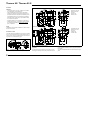
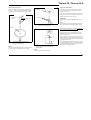
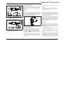
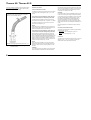
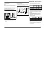
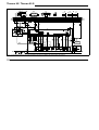
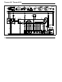
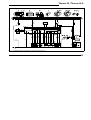
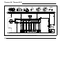
Water Heaters
Installation Instructions
Thermo 90
Thermo 90-TRS
Thermo 90 S
Thermo 90 S-TRS
(Transport of hazardous goods)
Type BW 80 (Petrol), Type Thermo 90 S B (Petrol)
Type DW 80 (Diesel), Type Thermo 90 S D (Diesel)
Operating Instructions must be read before
attempting to start up the heater.
4/1997
Thermo 90 / Thermo 90 S
Table of Contents
Page
Installation Instructions
1
Legal Provisions for Installation 1
Installation
2
Installation Example
3
Connection to the Vehicle’s Cooling System
4
Fuel Supply
4
Fuel Lines
6
Metering Pump
6
Combustion Air Supply
7
Exhaust Pipe
7
Electrical Connections
8
Circuit Diagrams
10
Initial Operation
17
Malfunctions
18
Technical Data
20
Variants
21
Template for heater mounting
bracket
23
Webasto Service Phone Line
25
I
Thermo 90 / Thermo 90 S
Installation Instructions
Legal Provisions for Installation
For testing the heater in accordance with articles 19, 20
oder 21 StVZO the following regulations are primarily to be
observed (§ 22 a StVZO):
NOTE:
These provisions are binding within the scope of the
StVZO (German Road Licensing Regulations) and
should also be observed in countries where no special locally applicable regulations are in effect!
Within the scope of the StVZO (German Road Licensing
Regulations) “General Design Certifications” have been
granted by the Federal Office for Motor Traffic for the
Thermo 90 water heater with the following marks of approval:
~S231 for Thermo 90 heaters Petrol type BW 80
~S232 for Thermo 90 heaters Diesel type DW 80 and
for Thermo 90-TRS heater Diesel type DW 80.
~S299 for Thermo 90 S heaters Petrol type
Thermo 90 S B
~S298 for Thermo 90 S heaters Diesel type
Thermo 90 S D and
for Thermo 90 S-TRS heaters Diesel type
Thermo 90 S D
The installation of the heaters must be performed in accordance with these Installation Instructions. The installation must be checked
a) upon the homologation of the vehicles in accordance
with § 20 StVZO
b) upon any individual test in accordance with
§ 21 StVZO, or
c) upon any examination in accordance with § 19 StVZO
by a registered expert or examiner for motor traffic, an
expert for automotive vehicles, or any other authorised
official, in accordance with paragraph 7.4a of
Appendix VIII to the StVZO
and in the case of item c) the proper installation must be
certified on the approval certificate contained on the design certification stating the following:
- vehicle manufacturer
- vehicle type and
- vehicle identification number
The effectiveness of the design certification (homologation) is dependent on this certificate. The approval certification is to be kept in the vehicle.
The year of the initial operation must be durably marked
on the type plate of the heater by the installer by removing
the years that do not apply.
Extracting the combustion air from the interior of the
vehicle is not permissible.
The discharge opening of the exhaust pipe must point upward, sideways or, in the case of routing the exhaust pipes
along the underside of the bottom vehicle, it must be located near the lateral or rear edge of the driver’s cab or vehicle. Exhaust pipes must be so routed that the possibility
of exhaust fumes entering the interior of the vehicle is
remote. The functioning of any parts of the vehicle essential for its operation must not be impaired.
main unaffected by torsional stresses in the vehicle, engine movement and the like. They must be protected
against mechanical damage. Fuel-carrying parts must be
protected against excessive heat and must be arranged
such that any dripping or evaporating fuel can neither collect nor be ignited by hot components or electrical equipment.
The heater must not be installed in rooms occupied by persons.
The operating state of the heater at any given time – at
least an indication as to whether it is “on” or “off” – must
be easily recognizable.
Webasto will not assume any liability if the installation instructions and the notes contained therein are not observed. The same applies to improperly performed repairs
or those where others than genuine replacement parts
have been used. In those cases, the heater’s General Design Certification and thus the General Operating Permit
(homologation) will be invalidated as a consequence.
The openings of the combustion air inlet and exhaust gas
outlet must be so designed that a spherical object of 16
mm in diameter cannot be introduced.
Electric lines, switchgear and control gear of the heater
must be so arranged in the vehicle that their proper functioning cannot be impaired under normal operating conditions.
For the routing of fuel lines and the installation of additional fuel tanks articles 45 and 46 StVZO are to be adhered to. The most important excerpts therefrom are as follows:
Fuel lines must be designed in such a way that they re-
Use of the Water Heaters
The Webasto Thermo 90 water heater in conjunction with
the vehicle heating system is designed to provide the following features:
- heating the driver’s cab,
- de-frosting the vehicle’s windscreen as well as
- preheating of water-cooled engines.
The water heater operates independently of the vehicle’s
engine and is connected to the cooling system, the fuel
system and the electrical system of the vehicle.
1
Thermo 90 / Thermo 90 S
Installation
Thermo 90
5
3
CAUTION:
- The legal provisions on page 1, relating to the installation of the heater, must be observed
- When installing the Thermo 90-TRS in vehicles designed for the transport of hazardous materials the requirements laid down in TRS 002 and TRS 003 (Technical Guidelines relating to the ordinance of transporting
hazardous goods on the road) must be fulfilled in addition to those of the StVZO.
Combustion air inlet
Exhaust gas outlet
Fuel inlet
Coolant inlet
Coolant outlet
1
2
3
4
5
Combustion air inlet
Exhaust gas outlet
Fuel inlet
Coolant inlet
Coolant outlet
4
- If the water heater is to be operated in a separately installed heating system, it is mandatory that the installation drawing be submitted to Webasto for approval
prior to installation.
NOTE:
The different vehicle-specific installation conditions should
be taken into account.
1
2
3
4
5
2
1
Thermo 90 S
5
3
Installation Location
The heater should be installed at a level as low as possible
so as to ensure automatic venting of the heater and the circulating pump. This is of special importance as the circulating pump is not of the self-priming type.
4
1
Fig. 2:
2
Dimensions of the Heater
Type Plate
Fig. 1:
2
Installation Position T90 / T90S
The type plate must be located in a place where it is protected against damage and be easily accessible once the
heater has been installed (or else, a type plate duplicate is
to be used).
The years not applicable are to be removed from the type
plate.
Thermo 90 / Thermo 90 S
cable harness
fuel line
exhaust pipe
water circuit
without non-return valve
Fig. 3:
with non-return valve and thermostat
Installation Examples for the Thermo 90 / Thermo 90 S Heater
Legend of Fig. 3
1 Heat exchanger of vehicle heating system
2 Switch for vehicle heating fan
3 Relay for vehicle fan
4 Digital timer
5 Fuse bank in vehicle
6 Non-return valve with leakage hole
7
8
9
10
11
12
13
T-piece
Vehicle engine
Heater
Circulating pump
Water pump
Radiator
Regulating valve
14
15
16
17
18
19
Exhaust silencer
Metering pump
Combustion air intake pipe
Thermostat
Electronic control unit
Control unit (alternative installation location of
Thermo 90 S)
3
Thermo 90 / Thermo 90 S
Connection to the Vehicle Cooling System
Fuel Supply
In the case of thermostat circuits only thermostats that
open at temperatures < 65°C should be used.
Fuel is drawn from the vehicle fuel tank or from a separate
fuel tank.
The heater is connected to the vehicle cooling system in
accordance with Fig. 3. The amount of coolant in the cooling system should be at least 6 liters.
In principle, only the water hoses supplied by Webasto
should be used. If this is not the case, the hoses must at
least comply with the requirements of DIN 73411. The
hoses are to be routed without any kinks and – for proper
venting – in an upward pitch, if possible. Hose connections
must be secured against slipping off by means of hose
clamps.
The values relating to the permissible pressure at the fuel
extraction point can be taken from the Table below.
NOTE:
The hose clamps must be tightened to a torque of 4 Nm.
Before the heater is started up for the first time or after the
coolant has been replaced, it must be ensured that the
cooling system is properly bled. Heater and piping should
be so installed that permanent self-bleeding of the system
is ensured.
permissible fuel feed height
H (m)
at max. permissible
overpressure (bar) in fuel
line
0.00
0.2
1.00
0.11
2.00
0.03
permissible fuel suction
height S (m)
at max. permissible
underpressure (bar) in fuel
tank
0.00
-0.10
0.50
-0.06
1.00
-0.02
Proper bleeding action can be recognized by the nearly silent operation of the circulating pump. Insufficient bleeding
can result in tripping the resettable temperature limiter.
l1 + l2 ≤ 10 m
l1 ≤ 1.2 m
l2 ≤ 8.8 m
Fig. 4:
4
Fuel Supply
Thermo 90 / Thermo 90 S
Vehicles with Diesel Engines
Vehicles with Petrol Engines
Plastic tank
Fuel must be drawn from the fuel tank or a separate tank
(see Figs. 5, 6 and 7). When fuel is supplied from a separate tank, any pressure-related influence can be excluded.
In the case of carburettor or injection engines equipped
with return lines, the heater’s fuel system is to be integrated in the return line.
In the case of carburettor engines without return line, the
fuel circuit of the heater is to be integrated in the flow line
between the vehicle’s fuel tank and pump.
Fuel extracting
device
Sealing ring
ANNOTATION
A fuel flow line can usually be identified by the in-line fuel
filter.
Sealing ring
Fig. 6:
Fuel Extraction From the Plastic Tank
(Extraction via Tank Drain Plug)
Tank fitting
Hole Pattern
NOTE:
If the vehicle’s fuel system is equipped with a vapour separator, fuel extraction is to take place upstream of same.
For fuel extraction from flow or return lines it is mandatory that the special Webasto fuel pickup (see Fig. 8)
be used.
The fuel pickup is to be so mounted that any air or gas
bubbles that may form are automatically discharged toward the tank (see Fig. 8).
Air or gas bubbles in the fuel line of the vehicle can form if
there is a leak in the vehicle’s carburettor or fuel pump or
in the case of ambient temperatures exceeding the vaporizing temperature of the fuel.
Fig. 5:
Fuel Extraction From the Plastic Tank
(Extraction via Tank Fitting)
Fig. 7:
NOTE:
After tank extracting device has been cut to length by sawing, remove any burr and metal chips from cut edge.
*
Webasto Tank Extracting Device
Fuel should not be extracted from within the vicinity of the
engine as gas bubbles are likely to form in the lines owing
to the heat radiating from the engine which may result in
malfunctions in the heating operation.
tank extracting device only to be used with
metal fuel tanks
NOTE:
The fitting must be made of sheet metal!
5
Thermo 90 / Thermo 90 S
Fuel Lines
correct
Only steel, copper and plastic pipes made of plasticized,
light-resistant and temperature-stabilized PA 11 or PA 12
(e.g. Mecanyl RWTL) in accordance with DIN 73378 may
be used.
NOTE:
Do not cut Mecanyl lines using a side cutter.
to engine
from tank
to metering pump
Fig. 8:
Webasto Fuel Pickup
If the heater is installed in vehicles equipped with injection
systems it is therefore to be determined whether the fuel
pump is mounted inside or outside the tank.
Where the fuel pump is located inside the tank, fuel may
only be extracted from the return line in which case it must
be ensured that the return line extends almost to the bottom of the tank and that it is not closed by a nonreturn
valve. Failing this, the return pipe can be extended.
Where the fuel pump is mounted outside the tank, the connection to the fuel system can be accomplished between
the fuel tank and the fuel pump.
6
clamp
incorrect
bubble
As in the majority of cases it is not possible to route the
lines in a continuous upward pitch, the inside diameter
must not exceed a given dimension. If the inside diameter
equals or is greater than 4 mm, air or gas bubbles accumulate which result in malfunctions if the lines sag or are
routed in a downward pitch. When the diamters shown in
Fig. 4 and 8 are used, you can be sure that no unwanted
bubbles will form.
Fig. 9:
The lines leading from the metering pump to the heater
should not be routed in a downward pitch.
Metering Pump with Damper
To prevent the fuel lines from sagging, freely suspended
lines must be secured. Mounting should be performed in
such a manner that the lines are protected against flying
stones and thermal influence (exhaust pipe).
bubble
Pipe/Hose Connection
The metering pump is a combined delivery/metering and
shutoff system and is subject to certain installation criteria
(see Figs. 4, 10 and 11).
Installation Location
Connecting 2 Pipes Using a Hose
The proper connection of fuel lines using a hose is shown
in Fig. 9.
Check for leakage!
Prior to installing the metering pump it must be ensured
that the maximum pressure prevailing at the fuel extraction
point is less than 0,2 bar.
It is recommended that the metering pump be installed in a
location which is sufficiently cool. On no account must the
permissible ambient temperature at any given operating
stage be in excess of + 20 °C in the case of petrol, and
+ 40°C in the case of Diesel variants.
Metering pump and fuel lines must not be located within
the radiation range of hot vehicle parts. If necessary, a radiation protection is to be provided.
The preferred installation location is near the tank.
Thermo 90 / Thermo 90 S
12-volts and 24-volts - Petrol and Diesel
Installation and Mounting
The combustion air inlet must not be located above the exhaust gas outlet.
The metering pump is to be attached by vibration-damping
suspension. The installation position is restricted in accordance with Figs. 10 and 11 in order to ensure sufficient selfventilation.
preferably
15°-90°
Fig. 10:
NOTE:
If it is not possible to route the combustion air line in a
downward pitch, a ø 4mm water drain hole is to be provided at the lowermost point.
Fuel Filter
If dirt in the fuel must be reckoned with, only Webasto filter,
order no. 487 171, should be used. Filter is preferably to
be installed in vertical position, where this is not possible, it
may also be installed horizontally (installation position 0°90°). Direction of flow to be observed!.
Metering Pump
Installation Position and Mounting
0 - 90°
12-volts and 24-volts - Diesel only
When the heater is installed in the vicinity of the vehicle
tank in a common installation space, combustion air must
be drawn in from the outside of the vehicle and the exhaust gas be discharged to the atmosphere. Lead-through
openings must be splash-proof.
If the heater is located in an enclosed installation housing,
a ventilation opening of at least 6 cm2 is required. If the
temperature in the installation housing exceeds the permissible ambient temperature of the heater (see Technical
Data), the ventilation opening must be enlarged after consultation with Webasto.
Exhaust Pipe
Fig. 12:
Fuel Filter
Installation Position to be Observed
Combustion Air Supply
Fig. 11:
Metering Pump
Installation Position horizontal
On no account must the combustion air be extracted from
areas where persons are present. The combustion air intake opening must not point in the direction of travel. It
must be so located that the possibility of clogging due to
contamination or snow and the drawing in of splash water
is remote.
The combustion air line (inside diameter min. 30 mm) may
have a length between 0.5m and 5m and may feature several bends totalling 360°. The smallest bending radius is
45 mm.
The exhaust pipe (inside diameter 38 mm) can have a
length between 0.5m and 5 m and may feature several
bends (totalling 360°, smallest bending radius 85 mm). It is
mandatory to provide an exhaust silencer which is to be installed near the heater.
The discharge opening of the exhaust pipe must not point
in the direction of travel (see Fig. 13).
The exhaust pipe discharge opening must be so located
that any clogging caused by snow or mud is not to be expected.
Rigid pipes made of unalloyed or alloyed steel with a minimum wall thickness of 1.0 mm or flexible tubes of alloyed
steel only are to be used as exhaust pipes. The exhaust
pipe is to be secured to the heater, e.g. by means of a
clamp. For further regulations refer to the Legal Provisions.
7
Thermo 90 / Thermo 90 S
Unique to Thermo 90-TRS: For legal provisions relating
Electrical Connections
to the routing of the exhaust pipe refer to Technical Information E3 - 5.10 (order no. 776 623).
Control Unit/Heater Connection
To ensure an angle of discharge of 90° ± 10°, it is required that the pipe clamp be attached no more than
150 mm, from the exhaust pipe end
The electrical connection of the heaters is to be carried out
in accordance with circuit diagrams Figs. 16, 17, 18, 19
and 20.
Connection upon the installation of Thermo 90 into a
vehicle for the transport of dangerous goods (TRS).
For legal provisions relating to the electrical connection
refer to Technical Information E3 - 5.10 (order no. 776 623).
The electrical connection is to be carried out in accordance with circuit diagram Fig. 17.
NOTE:
Switch S6 must be so installed that upon the start-up of a
pumping device either positive or negative potential is applied to the respective inputs of the control unit.
Connection upon the installation of Thermo 90 S into
a vehicle for the transport of dangerous goods (TRS).
When installing the Thermo 90 S heaters in vehicles for
the transport of dangerous goods, the requirements laid
down in TRS 002 and TRS 003 (Technical Guidelines relating to the directive concerning the carriage of dangerous
goods by road) must be fulfilled in addition to those of the
StVZO. The electrical connection is to be performed in accordance with circuit diagram Fig. 19 or 20.
direction of discharge approximately vertical 90° ± 10°
Fig. 13:
Exhaust Pipe Discharge Opening
Installation Position
NOTE:
Switch S7 must be installed in such a way that positive
potential is applied across the corresponding input of the
electronic control unit when a pumping device is put into
operation.
CAUTION:
If no ground connection is provided via Y2 or H5 when the
heater is activated, all TRS functions will be inoperative.
8
After positive potential has been applied across the X12/5
control unit input (auxiliary drive “ON”), a short 20-second
after-run period will follow and subsequently the control
unit will be in the ’fault lock-out’ state.
CAUTION:
In accordance with the Technical Guidelines relating to the
ordinance concerning the carriage of dangerous goods by
road, heaters may only be activated by means of a special,
manually operated switch located in the driver’s cabin.
If the heater is equipped with a standard digital timer it
must be ensured that pin 4 of the timer remains unassigned so that the heater can only be activated by means
of the instant heat button (circuit diagram available upon request).
No other digital timers are allowed to be used in TRS vehicles.
Connection of the Heater Controls
The heater can be switched on and off using the following
Webasto heater controls:
- Digital timer see circuit diagram Fig. 16 or 18
- Switch see circuit diagram Fig. 17 or 19.
Vehicle Fan
The vehicle fan is activated by means of a relay, see circuit
diagram Fig. 16, 17, 18, 19 or by means of a relay provided with an interior-temperature thermostat.
Thermo 90 / Thermo 90 S
Control Unit Thermo 90
Control Unit Thermo 90 S
NOTE:
Control units for the 12-volt variant are provided with red labelling, those for the 24-volt variant with green labelling.
In the installation position as shown in Fig. 15 the control
unit conforms to IP6K4K type of enclosure.
The control unit should be installed in a protected location,
preferably in the driver’s cab.
In the installation position as shown in Fig. 14 the control
unit has the degree of protection IP 54 and in any other installation position the degree of protection is IP 50.
Setting the Control Temperatures for Thermo 90
Table
Preset
Control Restart
Temperature
Idle
After
at Sensor
Period Control Idle
Period
negative at B6
80°C
90°C
75°C
B6 open
72°C
82°C
67°C
positive at B6
65°C
75°C
60°C
On the standard cable harness B6 is open.
NOTE:
The selected control idle period temperature of the heater
should lie below the opening temperature of the radiator
thermostat!
Setting the Control Temperatures for Thermo 90 S
Fig. 15:
Control Unit T 90 S (from 03/97), Installation
Position
If the signal “Motor on”/"Motor off" (terminal D+) is connected to the control unit X12 / 7, different control threshold values will take effect.
Preset
Control
Temperature Idle
at Sensor
Period
Fig. 14:
Control Unit, Installation Position
Restart After
Control Idle
Period
“Motor on”
72°C
82°C
67°C
“Motor off”
80°C
90°C
75°C
(only required for degree of protection IP 54 DIN 40050)
*
Space required for removing the receptacle
housings
If the signal of terminal D+ is not connected, the temperatures correspond to those of “Motor off”.
NOTE:
The temperature selected for the control idle period of the
heater should be lower than the opening temperature of
the radiator thermostat.
9
Thermo 90 / Thermo 90 S
Legend for circuit diagrams:
➀ this terminal is not used for petrol-operated heaters.
➁ For temperature codification (temperature at water outlet) refer to the table on page 9
< 7,5 m
7,5 - 15 m
2
0,75 mm
2
➂ Digital timer P1:
with positive voltage connected to pin 4 = continuous operation when “instant heat” is selected
positive voltage not connected to pin 4 = heating operation: 1 hour
➃ Digital timer P2:
with positive voltage connected to pin 10 = continuous operation when “instant heat” is selected
pin 10 open
= variable heating times can be programmed
(10 min. to 120 min.); basic setting: 120 min.
10
Colour of cables
Wire cross sections
1,0 mm
2
1,5 mm
2
2,5 mm
2
4,0 mm
1,0 mm
1,5 mm
2,5 mm
4,0 mm
6,0 mm
2
2
2
2
2
bl
br
ge
gn
gr
or
rt
sw
vi
ws
blue
brown
yellow
green
grey
orange
red
black
violet
white
Thermo 90 / Thermo 90 S
Pos.
A1
A2
B1
B2
B3
B4
E
F1
F2
F3
H1
H2
H3
H4
H5
H6
Designation
Heater
Electronic control unit
Flame detector
Temperature sensor
Temperature limiter
Interior-temperature thermostat
Pencil-type glow plug
Fuse 20A
Fuse 5A
Fuse 20A
Symbol for “Heating” on display
LED in pos. S4
LED
LED max. 20 mA
Lamp min. 1.2 W
Red LED (in pos. P2)
K1
K2
K5
K6
M1
M2
M3
P
P1
Relay (in pos. A2)
Relay (in pos. A2)
Relay
Relay
Motor
Motor
Motor
Tester
Digital timer 1529
Comment
Thermo 90/Thermo 90 S
flat fuse SAE J 1284
flat fuse SAE J 1284
flat fuse SAE J 1284
operation indicator (in pos. P1 or P2)
operation indicator (max. 2W)
illumination of symbols (in pos. P1 or P2)
flame indicator (option)
Operation indicator of pumping device
Illumination of ’instant heat’ button,
stand-by state indicator, operation indicator
main relay
for circulating pump
for vehicle fan
only req. if battery switch connected to neg. pole
combustion air fan
circulating pump
vehicle fan
for fault diagnosis
for presetting operating times
Pos.
P2
R
S1
S2
S3
S4
S5
S6
S7
S8
V106
V107
V108
X1
X2
X3
X4
X5
X6
X11
X12
X13
Y1
Y2
Designation
Digital timer, standard (1531)
Resistor
Switch for circulating pump
Switch
Switch
Switch
Disconnect switch 1 or 2-pole
Switch at pumping device
Switch, pumping device
Pushbutton
Transistor
Transistor
Transistor
Connector 12-pole
Connector 8-pole
Connector 12-pole
Connector 2-pole
Connector 2-pole
Connector 2-pole
Connector 12-pole
Connector 12-pole
Connector 2-pole
Metering pump
Magnetic valve
Comment
for presetting operating times
series resistor for H4
for separate switch-on
battery switch connected to positive pole
battery switch connected to negative pole
on / off
Emergency Stop switch electr. or pneum.
connected to positive or negative pole
connected to positive voltage
’instant heat’ button, remote control
in pos. A2
in pos. A2
in pos. A2
part of pos. A1
part of pos. P1
part of pos. P2
diagnostic system
at pos. A2 (ST 1)
at Pos. A2 (ST 2)
at pos. A2 (ST 3)
for pumping device
11
Thermo 90 / Thermo 90 S
ϑ
Fig. 16:
12
ϑ
System Diagram Thermo 90, 12 and 24V, with Digital Timer with 3 Time Settings, for legende refer to page 10 and 11
Thermo 90 / Thermo 90 S
ϑ
Fig. 17:
ϑ
System Diagram Thermo 90-TRS, 24V, for legende refer to page 10 and 11
13
Thermo 90 / Thermo 90 S
ϑ
Fig. 18:
14
System Diagram Thermo 90 S, 12 and 24V, with Digital Timer (standard) ,for legende refer to page 10 and 11
ϑ
Thermo 90 / Thermo 90 S
ϑ
Fig. 19:
ϑ
System Diagram Thermo 90 S - TRS, 24V, for legende refer to page 10 and 11
15
Thermo 90 / Thermo 90 S
ϑ
Fig. 20:
16
ϑ
System Diagram Thermo 90 S - TRS, 24V, without auxiliary drive, for legende refer to page 10 and 11
Thermo 90 / Thermo 90 S
Initial Operation
After the heater has been installed, the water circuit and
the fuel supply system must be thoroughly bled. When so
doing, the vehicle manufacturer’s instructions must be adhered to.
During a test run of the heater, all water and fuel connections must be checked for leakage and security. Should
the heater shut down during operation, troubleshooting activities must be carried out.
17
Thermo 90 / Thermo 90 S
Malfunctions
Diagnosis in the Event of a Fault Shutdown Thermo 90 S
Fault Shutdown
Check fuses and electrical connections.
If the flame fails to materialize fuel is delivered for max.
180 seconds.
After the occurrence of a malfunction, the fault is indicated
on the display of the digital timer if the heater is equipped
with a standard digital timer:
If the flame is extinguished during operation fuel is delivered for max. 90 seconds.
In the event of overheating (tripping of temperature
limiter) no fuel is delivered.
In the event of a shutdown initiated by the undervoltage
protection device
Thermo 90
Thermo 90 S
12 volts
10,5V ± 0,5V
10,5V – 0,5V
24 volts
21V ± 1V
21V – 1V
for more than 20 seconds,no fuel is delivered.
After the cause of malfunction has been eliminated, interlock deactivation is to be performed by switching the
heater off and then back on. If an overheating condition
has occurred the pushbutton of the temperature limiter
must be reset.
18
F 01 No start (after 2 start-up attempts)
F 02 Flame extinction (recurrent >5)
F 03 Undervoltage or overvoltage
F 04 Premature flame detection
F 05 Flame detector interruption or
flame detector short circuit
F 06 Temperature sensor interruption or
temperature sensor short circuit
F 07 Metering pump interruption or
metering pump short circuit
F 08 Blower motor interruption or
blower motor short circuit
blower motor incorrect speed
F 09 Pencil-type glow plug interruption or
pencil-type glow plug short circuit
F 10 Overheating
F 11 Circulating pump interruption or
circulation pump short circuit
If the heater is activated by the switch, the types of malfunctions are indicated by coded flashing signals via the
operation indicator light during the after-run period of the
heater.
After five short signals have been emitted, the long flashing pulses can be counted:
1x
2x
3x
4x
5x
No start (after 2 start-up attempts)
Flame extinction (recurrent >5)
Undervoltage or overvoltage
Premature flame detection
Flame detector interruption or
flame detector short circuit
6x Temperature sensor interruption or
temperature sensor short circuit
7x Metering pump interruption or
metering pump short circuit
8x Blower motor interruption or
blower motor short circuit
blower motor incorrect speed
9x Pencil-type glow plug interruption or
pencil-type glow plug short circuit
10x Overheating
11x Circulating pump interruption or
circulating pump short circuit
Thermo 90 / Thermo 90 S
Diagnosis in the Event of a Fault Shutdown of Thermo 90
Check fuses and electrical connections.
If the heater is activated by the switch or the timer with 3
time settings, the different types of malfunctions are indicated by coded flashing signals via the operation indicator
light during the after-run period of the heater.
After five short signals have been emitted, the long flashing pulses can be counted:
1x
2x
3x
4x
5x
6x
7x
8x
9x
No start (after 2 start-up attempts)
Flame extinction (recurrent >5)
Undervoltage
Premature flame detection
Flame detector interruption or
flame detector short circuit
Temperature sensor interruption or
temperature sensor short circuit
Metering pump interruption or
metering pump short circuit
Blower motor interruption or
blower motor short circuit
blower motor incorrect speed
Pencil-type glow plug interruption or
pencil-type glow plug short circuit
19
Thermo 90 / Thermo 90 S
Technical Data
Unless tolerances are shown within the technical data
table on the right, a tolerance of ± 10% applies at an ambient temperature of +20°C and at rated voltage.
Electrical components:
Control unit, motors for combustion air fan and circulating
pump, pencil-type glow plug, switch and digital timer (presetting of operating times not possible in the case of TRS
vehicles) are designed either for 12-volt or 24-volt operation. Components such as thermal cut-out, temperature
sensor and flame detector are identical in 12 V and
24 V heaters.
Heater
Thermo 90
Petrol
Thermo 90 S
Petrol
Type
BW 80
Thermo 90 S B
DW 80
Thermo 90 S D
Mark of approval
~S231
~S299
~S232
~S298
Type
Heat output
Fuel consumption
Fuel for Thermo 90 and
Thermo 90-TRS (Diesel):
The Diesel fuel specified by the vehicle manufacturer is
suitable as fuel for the heater.
Any negative effect caused by additives is not known.
When the fuel for the heater is drawn from the vehicle’s
fuel tank the vehicle manufacturer’s specifications concerning additives are to be observed.
When changing to cold-resistant fuels, the heater must be
operated for about 15 minutes to ensure that the fuel line
and the fuel pump are also filled with the new fuel.
Max.
control range
2,0 kW - 7,6 kW
Petrol
Diesel
Max.
control range
0,25 l/h - 1,0 l/h
1,1 l/h
0,19 l/h - 0,9 l/h
Rated voltage
Operating voltage range
Max.
control range
Permissible ambient temperature:
Heater:
- operation
- storage
Control unit:
- operation
- storage
Metering pump:
- operation
- storage
Permissible operating overpressure
(heat carrier)
Capacity of heat exchanger
12 Volt
12 oder 24 Volt 1)
10 ... 15 bzw. 20 ... 30 volts
37 W - 83 W
90 W
37 W - 83 W
-40° ... +110°C (90°C 2))
-40° ... +110°C (90°C 2))
-40° ... + 75°C
-40° ... + 85°C
-40° ... + 20°C | -40° ... + 40°C
-40° ... + 85°C
Max
2,0 bar
0,15 l
+40°C
Minimum circuit capacity
Flow rate of circulating pump against
0.15 bar
CO2 content in exhaust gas (permissible Max.
operating range)
CO2-Setting values at RT and a
Max.
geograph. altitude above sea level
Dimensions of heater
(tolerance ± 3 mm)
Weight
20
9,1 kW
1,8 kW - 7,6 kW
10 ... 15 volts
Max. combustion air intake temperature
1)
2)
Thermo 90 Thermo 90 S
Diesel
Diesel
Thermo 90- Thermo 90 STRS
TRS
water heater with Ferro-tec technology
Fuel
Rated power consumption with
circulating pump (without vehicle fan)
Fuel for Thermo 90 Petrol-Type Heater:
The fuel specified by the vehicle manufacturer is suitable
as fuel for the heater.
Both leaded and unleaded fuel may be used.
Operation
Thermo 90-TRS: 24 volts only
Thermo 90 S with control unit mounted to the heater
6,00 l
1650 l/h
10 ... 12,0 Vol .-%
0m
10%
500m
10,6%
1000m
11,3%
length 310 mm (355 mm 2))
width 133 mm
height 220 mm
4,8 kg
Thermo 90 / Thermo 90 S
Variants Thermo 90
Variants Thermo 90 S
Thermo 90 Petrol-Type
(Type BW 80)
Water heater for “petrol” fuel
Thermo 90 S Petrol-Type
(Typ Thermo 90 S B)
Water heater for “petrol” fuel
Thermo 90 Diesel-Type
(Type DW 80)
Water heater for “Diesel” fuel
Thermo 90 S Diesel-Type
(Typ Thermo 90 S D)
Water heater for “Diesel” fuel
Thermo 90-TRS (Type DW 80)
Water heater Thermo 90 with TRS
configuration
specially designed for use in vehicles carrying hazardous materials
Thermo 90-TRS
(Typ Thermo 90 S D)
Water heater Thermo 90 S with
TRS configuration
specially designed for use in vehicles carrying hazardous materials
The petrol-fuelled Thermo Top 90
water heaters are designed to
operate on 12 V, the Thermo 90
Diesel heaters on 12 or 24 V, and
the Thermo 90-TRS heaters operate on 24 V only.
The petrol-fuelled Thermo Top 90 S
water heaters are designed to
operate on 12 V, the Thermo 90 S
Diesel heaters on 12 or 24 V, and
the Thermo 90-TRS heaters operate on 24 V only.
21
Thermo 90 / Thermo 90 S
22
Template for heater mounting bracket
Scale 1:1
Gabarit de perçage pour le support de l’appareil de chauffage
Echelle 1:1
Thermo 90 / Thermo 90 S
24
Subject to change
Webasto Thermosysteme GmbH
82131 Stockdorf . Kraillinger Str. 5 . Phone (089) 85794-0
Fax (089) 8 57 94-448 . Telex 5 23 647 webas d