1
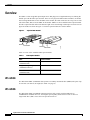
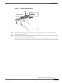
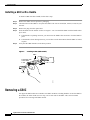
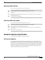
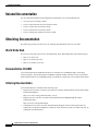
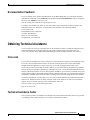
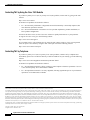
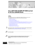
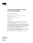
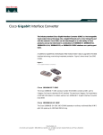
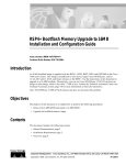
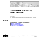
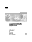
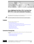
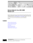
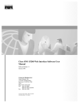
Gigabit Interface Converter Installation Note
Product Numbers: WS-G5484(=), WS-G5486(=), WS-G5487(=)
This installation note provides the technical specifications and installation instructions for the Gigabit
Interface Converters (GBICs) that you install in the Catalyst 6000, Catalyst 5000, and Catalyst 4000
family Gigabit Ethernet ports that accept GBICs.
Contents
This publication consists of these sections:
•
Overview, page 2
•
Safety Overview, page 6
•
Required Tools, page 8
•
Installing the GBIC, page 8
•
Removing a GBIC, page 10
•
Standards Compliance Specifications, page 11
•
Translated Safety Warnings, page 12
•
Related Documentation, page 18
•
Obtaining Documentation, page 18
•
Obtaining Technical Assistance, page 19
Corporate Headquarters: Cisco Systems, Inc., 170 West Tasman Drive, San Jose, CA 95134-1706 USA
Cisco Systems, Inc. All rights reserved.
78-5399-03 Rev. A0
Overview
Overview
The GBIC is a hot-swappable input/output device that plugs into a Gigabit Ethernet port, linking the
module port with the fiber-optic network. There are two physical GBIC models available; one model
has a locking handle that secures the GBIC in the module; the other model uses two clips, one on each
side of the GBIC, that secure the GBIC in the module. GBICs are also available in three optical models.
The three optical models differ in the distance light can be sent through a fiber-optic network. The two
physical models are shown in Figure 1. The three optical models are listed in Table 1.
Figure 1
Physical GBIC Models
Clip
Handle
Receiver
Transmitter
51178
Receiver
Transmitter
Table 1 is a list of the available GBIC optical models.
Table 1
GBIC Optical Models
GBIC
Product Number
Short wavelength
(1000BASE-SX)
WS-G5484
Long wavelength/long haul
(1000BASE-LX/LH)
WS-G5486
Extended distance
(1000BASE-ZX)
WS-G5487
WS-G5484
The WS-G5484 GBIC (1000BASE-SX) operates on ordinary multimode fiber (MMF) link spans of up
to 1804 feet (550 meters) in length (See Table 5 on page 4).
WS-G5486
The WS-G5486 GBIC (1000BASE-LX/LH) interfaces fully comply with the IEEE 802.3z
1000BASE-LX standard. However, their higher optical quality allows them to reach 10 km over
single-mode fiber (SMF) versus the 5 km specified in 802.3z.
Gigabit Interface Converter Installation Note
2
78-5399-03 Rev. A0
Overview
When using an LX/LH GBIC with a 62.5-micron diameter MMF, you must install a mode-conditioning
patch cord (CAB-GELX-625 or equivalent) between the GBIC and the MMF cable on both the transmit
and receive ends of the link in the following situations:
•
Less than 328 feet (100 meters). When illuminating short lengths of MMF with an LX/LH GBIC,
the mode-conditioning patch cord reduces the amount of optical power coupled into the MMF.
Excessive power can saturate the LX/LH receiver causing an elevated bit error rate (BER).
•
Greater than 984 feet (300 meters). When illuminating long lengths of MMF with an LX/LH GBIC,
the mode-conditioning patch cord offsets the laser light to reduce the possibility of differential
mode delay.
WS-G5487
The WS-G5487 GBIC (1000BASE-ZX) operates on ordinary SMF link spans of up to 70 km in length.
Link spans of up to 100 km are possible using premium SMF or dispersion-shifted SMF (premium SMF
has a lower attenuation per unit length than ordinary SMF; dispersion-shifted SMF has both lower
attenuation per unit length and less dispersion).
The WS-G5487 GBIC must be coupled to SMF cable, which is the cable type typically used in
long-haul telecommunications applications. The WS-G5487 GBIC will not operate correctly when
coupled to MMF cable, and it is not intended to be used in application environments (e.g., building
backbones or horizontal cabling) where MMF is frequently used.
The WS-G5487 GBIC is intended to be used as a physical medium dependent (PMD) component for
Gigabit Ethernet interfaces. This GBIC operates at a signaling rate of 1250 MBaud, transmitting and
receiving 8B/10B encoded data.
When you have shorter distances of SMF, you might need to insert an in-line optical attenuator in the
link to avoid overloading the receiver:
Note
•
Insert a 10-dB in-line optical attenuator between the fiber-optic cable plant and the receiving port
on the WS-G5487 GBIC at each end of the link whenever the fiber-optic cable span is less than
15.5 miles (25 km).
•
Insert a 5-dB in-line optical attenuator between the fiber-optic cable plant and the receiving port on
the WS-G5487 GBIC at each end of the link whenever the fiber-optic cable span is equal to or
greater than 15.5 miles (25 km) and less than 31 miles (50 km).
The maximum number of installed 1000BASE-ZX GBICs is limited in each Catalyst
chassis. These limits fall within the emission specifications for these products. Table 2
lists the 1000BASE-ZX GBIC limits for the different Catalyst systems.
Table 2
Maximum Number of 1000BASE-ZX (WS-G5487) GBICs Per Platform
Platform
Maximum number of 1000BASE-ZX GBICs
Catalyst 4000 family
12 to comply with EN55022 Class B and FCC Class A
Catalyst 5000 family
12 to comply with FCC Class A
Catalyst 6000 family
12 to comply with EN55022 Class B
24 to comply with FCC Class A
Gigabit Interface Converter Installation Note
78-5399-03 Rev. A0
3
Overview
Specifications
GBIC specifications are listed in Table 3. GBIC transmitter power and receiver sensitivity values are
listed in Table 4.
Table 3
GBIC Specifications
Specification
Description
Dimensions (H x W x D)
0.39 x 1.18 x 2.56 inches
(1 x 3 x 6.5 cm)
Weight
1 ounce maximum (28.4 grams)
Connectors
Multimode fiber-optic: SC
Single-mode fiber-optic: SC
Connector polishing
SX — The SX GBIC uses ball lenses
and an air gap. A flat polish on the
fiber-optic interface connectors is
suggested.
LX/LH — Super Physical Contact
with a 20 micron radius
Table 4
GBIC Channel Insertion Loss
Specification
1000BASE-SX
1000BASE-LX/LH
1000BASE-ZX
Transmitter output power
(minimum/maximum)
0/–9.5 dBm
–3/–9.5 dBm
0/4.77 dBm
Receiver maximum input power
0 dBm
–3 dBm
–3 dBm
Receiver sensitivity
–17 dBm
–19 dBm
–23 dBm
50 micron MMF
3.4 dB
4.4 dB
N/A
62.5 micron MMF
3.2 dB
6 dB
N/A
9 micron SMF
N/A
6.5 dB
21.5 dB
Channel insertion loss
Port Cabling Specifications
Table 5 provides cabling specifications for the GBICs that you install in the Gigabit Ethernet port. Note
that all GBIC ports have SC-type connectors, and the minimum cable distance for all GBICs listed
(MMF and SMF) is 6.5 feet (2 meters).
Gigabit Interface Converter Installation Note
4
78-5399-03 Rev. A0
Overview
Table 5
GBIC Port Cabling Specifications
GBIC
SX
2
Wavelength
(nm)
Fiber Type
Core Size1
(micron)
Modal
Bandwidth
(MHz/km)
Cable Distance
850
62.5
160
722 feet (220 meters)
62.5
200
902 feet (275 meters)
50.0
400
1640 feet (500 meters)
50.0
500
1804 feet (550 meters)
62.5
500
1804 feet (550 meters)
50.0
400
1804 feet (550 meters)
50.0
500
1804 feet (550 meters)
SMF
8.3/9/10
–
6.2 miles (10 km)
SMF
8.3/9/10
–
43.5 miles (70 km)
8
–
62.1 miles (100 km)4
MMF
(WS-G5484)
LX/LH
1310
MMF3
(WS-G5486)
ZX
1550
(WS-G5487)
1. The numbers given for multimode fiber-optic cable refer to the core diameter. For single-mode fiber-optic cable,
8.3 microns refers to the core diameter. The 9-micron and 10-micron values refer to the mode-field diameter (MFD), which
is the diameter of the light-carrying portion of the fiber. This area consists of the fiber core plus a small portion of the
surrounding cladding. The MFD is a function of the core diameter, the wavelength of the laser, and the refractive index
difference between the core and the cladding.
2. Use with MMF only.
3. When using an LX/LH GBIC with 62.5-micron diameter MMF, you must install a mode-conditioning patch cord
(CAB-GELX-625 or equivalent) between the GBIC and the MMF cable on both the transmit and receive ends of the link.
The mode-conditioning patch cord is required for link distances less than 328 feet (100 m) or greater than 984 feet (300 m).
The mode-conditioning patch cord prevents overdriving the receiver for short lengths of MMF and reduces differential
mode delay for long lengths of MMF.
4. Requires dispersion-shifted single-mode fiber-optic cable.
Note
The mode-conditioning patch cord (CAB-GELX-625 or equivalent) is required to comply
with IEEE standards. The IEEE found that link distances could not be met with certain
types of fiber-optic cable cores. The solution is to launch light from the laser at a precise
offset from the center by using the mode-conditioning patch cord. At the output of the
patch cord, the LX/LH GBIC is compliant with the IEEE 802.3z standard for
1000BASE-LX.
Gigabit Interface Converter Installation Note
78-5399-03 Rev. A0
5
Safety Overview
Safety Overview
Safety warnings appear throughout this publication in procedures that, if performed incorrectly, may
harm you. A warning symbol precedes each warning statement.
Warning
This warning symbol means danger. You are in a situation that could cause bodily
injury. Before you work on any equipment, be aware of the hazards involved with
electrical circuitry and be familiar with standard practices for preventing accidents.
To see translations of the warnings that appear in this publication, refer to the
"Translated Safety Warnings" section in this document.
Waarschuwing
Dit waarschuwingssymbool betekent gevaar. U verkeert in een situatie die lichamelijk
letsel kan veroorzaken. Voordat u aan enige apparatuur gaat werken, dient u zich
bewust te zijn van de bij elektrische schakelingen betrokken risico's en dient u op de
hoogte te zijn van standaard maatregelen om ongelukken te voorkomen. Voor
vertalingen van de waarschuwingen die in deze publicatie verschijnen, kunt u het
gedeelte “Translated Safety Warnings” (Vertalingen van veiligheidsvoorschriften)
raadplegen in dit document.
Varoitus
Tämä varoitusmerkki merkitsee vaaraa. Olet tilanteessa, joka voi johtaa
ruumiinvammaan. Ennen kuin työskentelet minkään laitteiston parissa, ota selvää
sähkökytkentöihin liittyvistä vaaroista ja tavanomaisista onnettomuuksien
ehkäisykeinoista. Tässä julkaisussa esiintyvien varoitusten käännökset löydät tämän
asiakirjan "Translated Safety Warnings" (käännetyt turvallisuutta koskevat
varoitukset).
Attention
Ce symbole d'avertissement indique un danger. Vous vous trouvez dans une situation
pouvant causer des blessures ou des dommages corporels. Avant de travailler sur un
équipement, soyez conscient des dangers posés par les circuits électriques et
familiarisez-vous avec les procédures couramment utilisées pour éviter les accidents.
Pour prendre connaissance des traductions d’avertissements figurant dans cette
publication, consultez la section « Translated Safety Warnings » (Traduction des avis
de sécurité) de ce document.
Warnung
Dieses Warnsymbol bedeutet Gefahr. Sie befinden sich in einer Situation, die zu einer
Körperverletzung führen könnte. Bevor Sie mit der Arbeit an irgendeinem Gerät
beginnen, seien Sie sich der mit elektrischen Stromkreisen verbundenen Gefahren
und der Standardpraktiken zur Vermeidung von Unfällen bewußt. Übersetzungen der
in dieser Veröffentlichung enthaltenen Warnhinweise finden Sie im Abschnitt
“Translated Safety Warnings” (Übersetzung der Warnhinweise) in diesem Dokument.
Avvertenza
Questo simbolo di avvertenza indica un pericolo. La situazione potrebbe causare
infortuni alle persone. Prima di lavorare su qualsiasi apparecchiatura, occorre
conoscere i pericoli relativi ai circuiti elettrici ed essere al corrente delle pratiche
standard per la prevenzione di incidenti. La traduzione delle avvertenze riportate in
questa pubblicazione si trova nella documento “Translated Safety Warnings”
(Traduzione delle avvertenze di sicurezza) nel presente documento.
Gigabit Interface Converter Installation Note
6
78-5399-03 Rev. A0
Safety Overview
Advarsel
Dette varselsymbolet betyr fare. Du befinner deg i en situasjon som kan føre til
personskade. Før du utfører arbeid på utstyr, må du vare oppmerksom på de
faremomentene som elektriske kretser innebærer, samt gjøre deg kjent med vanlig
praksis når det gjelder å unngå ulykker. Hvis du vil se oversettelser av de advarslene
som finnes i denne publikasjonen, kan du se i avsnittet "Translated Safety Warnings"
[Oversatte sikkerhetsadvarsler] i dette dokumentet.
Aviso
Este símbolo de aviso indica perigo. Encontra-se numa situação que lhe poderá causar
danos físicos. Antes de começar a trabalhar com qualquer equipamento,
familiarize-se com os perigos relacionados com circuitos eléctricos, e com quaisquer
práticas comuns que possam prevenir possíveis acidentes. Para ver as traduções dos
avisos que constam desta publicação, consulte a secção “Translated Safety
Warnings” - “Traduções dos Avisos de Segurança” neste documento.
¡Advertencia!
Este símbolo de aviso significa peligro. Existe riesgo para su integridad física. Antes
de manipular cualquier equipo, considerar los riesgos que entraña la corriente
eléctrica y familiarizarse con los procedimientos estándar de prevención de
accidentes. Para ver una traducción de las advertencias que aparecen en esta
publicación, consultar la sección titulada “Translated Safety Warnings” que aparece
en este documento.
Varning!
Denna varningssymbol signalerar fara. Du befinner dig i en situation som kan leda till
personskada. Innan du utför arbete på någon utrustning måste du vara medveten om
farorna med elkretsar och känna till vanligt förfarande för att förebygga skador. Om du
vill se översättningar av de varningar som visas i denna publikation, se avsnittet
"Translated Safety Warnings" [Översatta säkerhetsvarningar] i detta dokument.
Warning
Before you install, operate, or service the system, read the Site Preparation and Safety
Guide . This guide contains important safety information you should know before
working with the system.
Warning
Only trained and qualified personnel should be allowed to install, replace, or service
this equipment.
Warning
Class 1 laser product.
Warning
Because invisible laser radiation may be emitted from the aperture of the port when no
cable is connected, avoid exposure to laser radiation and do not stare into open
apertures.
Gigabit Interface Converter Installation Note
78-5399-03 Rev. A0
7
Required Tools
Warning
Ultimate disposal of this product should be handled according to all national laws and
regulations.
Warning
During this procedure, wear grounding wrist straps to avoid ESD damage to the card. Do
not directly touch the backplane with your hand or any metal tool, or you could shock
yourself.
Required Tools
No tools are required to remove or install a GBIC.
Installing the GBIC
Two physical GBIC models are available. One GBIC model has a locking handle to secure the GBIC in
the module; the other model uses two clips, one on each side of the GBIC. This section contains the
procedures for installing both GBIC models.
Installing a GBIC with Clips
To install a GBIC that has clips, follow these steps:
Step 1
Remove the GBIC from its protective packaging.
Step 2
Check the label on the GBIC to verify that the GBIC is the correct model (SX, LX/LH, or ZX) for your
network.
Step 3
Grip the sides of the GBIC with your thumb and forefinger and insert the GBIC into the module
socket, as shown in Figure 2.
Note
GBICs are keyed to prevent incorrect insertion.
Gigabit Interface Converter Installation Note
8
78-5399-03 Rev. A0
Installing the GBIC
Figure 2
Installing a GBIC (With Clips)
GBIC
Squeeze in clips
and slide GBIC
into slot
NK
LI
51180
Plug
Step 4
Slide the GBIC through the flap covering the socket opening until you hear a click indicating the
GBIC is locked into the slot.
Step 5
When you are ready to attach the network interface fiber-optic cable, remove the plug from the GBIC
optical bore and save the plug for future use.
Gigabit Interface Converter Installation Note
78-5399-03 Rev. A0
9
Removing a GBIC
Installing a GBIC with a Handle
To install a GBIC that has a handle, follow these steps:
Step 1
Remove the GBIC from its protective packaging.
Step 2
Check the label on the GBIC to verify that the GBIC is the correct model (SX, LX/LH, or ZX) for your
network.
Step 3
Remove the plug from the optical bore.
Step 4
Slide the GBIC into the module socket. See Figure 3. You can install the GBIC with the handle either
up or down.
Step 5
a.
If the handle is up during insertion, you must lower the handle after insertion to lock the GBIC in
place.
b.
If the handle is down during insertion, you will hear a click that indicates that the GBIC is locked
in place.
Verify that the GBIC handle is in the down position.
Figure 3
Installing a GBIC (With Handle)
GBIC
Pull handle down
to lock GBIC
in slot
NK
LI
51179
Plug
Removing a GBIC
Two physical GBIC models are available. One GBIC model has a locking handle to secure the GBIC in
the module; the other model uses two clips, one on each side of the GBIC. This section contains
procedures for removing both GBIC models.
Gigabit Interface Converter Installation Note
10
78-5399-03 Rev. A0
Standards Compliance Specifications
Removing a GBIC with Clips
If you are removing a GBIC that has clips, follow these steps:
Step 1
Disconnect the network fiber-optic cable from the GBIC SC-type connector.
Step 2
Release the GBIC from the slot by simultaneously squeezing the two plastic tabs (one on each side of
the GBIC).
Step 3
Slide the GBIC out of the Gigabit Ethernet module slot. A flap drops down to protect the Gigabit
Ethernet module connector.
Step 4
Place the GBIC in an antistatic bag.
Removing a GBIC with a Handle
If you are removing a GBIC with a handle, follow these steps:
Step 1
Disconnect the network fiber-optic cable from the GBIC SC-type connector.
Step 2
Rotate the handle up to release the GBIC from the slot.
Step 3
Grip the handle or the sides of the GBIC and slide the GBIC out of the slot. A flap drops down to
protect the slot.
Step 4
Place the GBIC in an antistatic bag.
Standards Compliance Specifications
This section provides compliance information for the GBIC.
FCC Class A Compliance
This equipment has been tested and found to comply with the limits for a Class A digital device,
pursuant to part 15 of the FCC rules. These limits are designed to provide reasonable protection against
harmful interference when the equipment is operated in a commercial environment. This equipment
generates, uses, and can radiate radio-frequency energy and, if not installed and used in accordance with
the instruction manual, may cause harmful interference to radio communications. Operation of this
equipment in a residential area is likely to cause harmful interference, in which case users will be
required to correct the interference at their own expense.
Gigabit Interface Converter Installation Note
78-5399-03 Rev. A0
11
Translated Safety Warnings
You can determine whether your equipment is causing interference by turning it off. If the interference
stops, it was probably caused by the Cisco equipment or one of its peripheral devices. If the equipment
causes interference to radio or television reception, try to correct the interference by using one or more
of the following measures:
•
Turn the television or radio antenna until the interference stops.
•
Move the equipment to one side or the other of the television or radio.
•
Move the equipment farther away from the television or radio.
•
Plug the equipment into an outlet that is on a different circuit from the television or radio. (That is,
make certain the equipment and the television or radio are on circuits controlled by different circuit
breakers or fuses.)
Modifications to this product not authorized by Cisco Systems could void the FCC approval and negate
your authority to operate the product.
Class 1 Laser Compliance
This product has been tested and found to comply with the limits for Class 1 laser for IEC825,
EN60825, and 21CFR1040 specifications.
Translated Safety Warnings
This section contains the translations of the warnings included in this document.
Safety Information Referral Warning
Warning
Before you install, operate, or service the system, read the Site Preparation and Safety
Guide. This guide contains important safety information you should know before
working with the system.
Waarschuwing
Lees de handleiding Voorbereiding en veiligheid van de locatie Handleiding voordat u
het systeem installeert of gebruikt of voordat u onderhoud aan het systeem uitvoert.
Deze handleiding bevat belangrijke beveiligingsvoorschriften waarvan u op de hoogte
moet zijn voordat u met het systeem gaat werken.
Varoitus
Ennen kuin asennat järjestelmän tai käytät tai huollat sitä, lue Asennuspaikan
valmistelu-jaturvaopas -opasta. Tässä oppaassa on tärkeitä turvallisuustietoja, jotka
tulisi tietää ennen järjestelmän käyttämistä.
Attention
Avant d'installer le système, de l'utiliser ou d'assurer son entretien, veuillez lire le
Guide de sécurité et de préparation du site . Celui-ci présente des informations
importantes relatives à la sécurité, dont vous devriez prendre connaissance.
Gigabit Interface Converter Installation Note
12
78-5399-03 Rev. A0
Translated Safety Warnings
Warnung
Avvertenza
Advarsel
Aviso
¡Advertencia!
Varning!
Warnhinweis Bevor Sie das System installieren, in Betrieb setzen oder warten, lesen
Sie die Anleitung zur Standortvorbereitung und Sicherheitshinweise . Dieses
Handbuch enthält wichtige Informationen zur Sicherheit, mit denen Sie sich vor dem
Verwenden des Systems vertraut machen sollten.
Prima di installare, mettere in funzione o effettuare interventi di manutenzione sul
sistema, leggere le informazioni contenute nella documentazione sulla Guida alla
sicurezza . Tale guida contiene importanti informazioni che è necessario acquisire
prima di iniziare qualsiasi intervento sul sistema.
Før du installerer, tar i bruk eller utfører vedlikehold på systemet, må du lese
Veiledning for stedsklargjøring og sikkerhet . Denne håndboken inneholder viktig
informasjon om sikkerhet som du bør være kjent med før du begynner å arbeide med
systemet.
Antes de instalar, funcionar com, ou prestar assistência ao sistema, leia o Guia de
Preparação e Segurança do Local . Este guia contém informações de segurança
importantes que deve conhecer antes de trabalhar com o sistema.
Antes de instalar, manejar o arreglar el sistema, le aconsejamos que consulte la Guía
de prevención y preparación de una instalación . Esta guía contiene importante
información para su seguridad que debe saber antes de comenzar a trabajar con el
sistema.
Innan du installerar, använder eller utför service på systemet ska du läsa
Förberedelser och säkerhet Handbok . Denna handbok innehåller viktig
säkerhetsinformation som du bör känna till innan du arbetar med systemet.
Qualified Personnel Warning
Warning
Waarschuwing
Varoitus
Only trained and qualified personnel should be allowed to install, replace, or service
this equipment.
Deze apparatuur mag alleen worden geïnstalleerd, vervangen of hersteld door
bevoegd geschoold personeel.
Tämän laitteen saa asentaa, vaihtaa tai huoltaa ainoastaan koulutettu ja laitteen
tunteva henkilökunta.
Attention
Il est vivement recommandé de confier l'installation, le remplacement et la
maintenance de ces équipements à des personnels qualifiés et expérimentés.
Warnung
Das Installieren, Ersetzen oder Bedienen dieser Ausrüstung sollte nur geschultem,
qualifiziertem Personal gestattet werden.
Avvertenza
Questo apparato può essere installato, sostituito o mantenuto unicamente da un
personale competente.
Gigabit Interface Converter Installation Note
78-5399-03 Rev. A0
13
Translated Safety Warnings
Advarsel
Bare opplært og kvalifisert personell skal foreta installasjoner, utskiftninger eller
service på dette utstyret.
Aviso
Apenas pessoal treinado e qualificado deve ser autorizado a instalar, substituir ou
fazer a revisão deste equipamento.
¡Advertencia!
Varning!
Solamente el personal calificado debe instalar, reemplazar o utilizar este equipo.
Endast utbildad och kvalificerad personal bör få tillåtelse att installera, byta ut eller
reparera denna utrustning.
Class 1 Laser Product Warning
Warning
Waarschuwing:
Varoitus:
Avertissement :
Warnung:
Avvertenza.
Advarsel!
Class 1 Laser Product
Waarschuwing voor klasse 1 laserprodukten
lasertuote luokka 1
Produits Laser Class 1
Produkt-Warnhinweis zu Lasergeräten der Klasse 1
Prodotto Laser di Classe 1
Advarsel for laserprodukter i klasse 1
Aviso
Aviso sobre produtos a laser da Classe 1
Aviso
É Aviso sobre producto láser de Clase 1
Varning!
Varning beträffande laserprodukt, klass 1
Gigabit Interface Converter Installation Note
14
78-5399-03 Rev. A0
Translated Safety Warnings
Invisible Laser Radiation Warning
Warning
Waarschuwing
Varoitus
Because invisible laser radiation may be emitted from the aperture of the port when no
cable is connected, avoid exposure to laser radiation and do not stare into open
apertures.
Omdat er onzichtbare laserstraling uit de opening van de poort geëmitteerd kan
worden wanneer er geen kabel aangesloten is, dient men om blootstelling aan
laserstraling te vermijden niet in de open openingen te kijken.
Kun porttiin ei ole kytketty kaapelia, portin aukosta voi vuotaa näkymätöntä
lasersäteilyä. Älä katso avoimiin aukkoihin, jotta et altistu säteilylle.
Attention
Etant donné qu’un rayonnement laser invisible peut être émis par l’ouverture du port
quand aucun câble n’est connecté, ne pas regarder dans les ouvertures béantes afin
d’éviter tout risque d’exposition au rayonnement laser.
Warnung
Aus der Öffnung des Ports kann unsichtbare Laserstrahlung austreten, wenn kein
Kabel angeschlossen ist. Kontakt mit Laserstrahlung vermeiden und nicht in offene
Öffnungen blicken.
Avvertenza
Poiché quando nessun cavo è collegato alla porta, da quest’ultima potrebbe essere
emessa radiazione laser invisibile, evitare l’esposizione a tale radiazione e non
fissare con gli occhi porte a cui non siano collegati cavi.
Advarsel
Aviso
Usynlige laserstråler kan sendes ut fra åpningen på utgangen når ingen kabel er
tilkoblet. Unngå utsettelse for laserstråling og se ikke inn i åpninger som ikke er
tildekket.
Evite uma exposição à radiação laser e não olhe através de aberturas expostas,
porque poderá ocorrer emissão de radiação laser invisível a partir da abertura da
porta, quando não estiver qualquer cabo conectado.
¡Advertencia!
Cuando no esté conectado ningún cable, pueden emitirse radiaciones láser invisibles
por el orificio del puerto. Evitar la exposición a radiaciones láser y no mirar fijamente
los orificios abiertos.
Varning!
Osynliga laserstrålar kan sändas ut från öppningen i porten när ingen kabel är
ansluten. Undvik exponering för laserstrålning och titta inte in i ej täckta öppningar.
Gigabit Interface Converter Installation Note
78-5399-03 Rev. A0
15
Translated Safety Warnings
Product Disposal Warning
Warning
Ultimate disposal of this product should be handled according to all national laws and
regulations.
Waarschuwing
Het uiteindelijke wegruimen van dit product dient te geschieden in overeenstemming
met alle nationale wetten en reglementen.
Varoitus
Tämä tuote on hävitettävä kansallisten lakien ja määräysten mukaisesti.
Attention
La mise au rebut ou le recyclage de ce produit sont généralement soumis à des lois
et/ou directives de respect de l'environnement. Renseignez-vous auprès de
l'organisme compétent.
Warnung
Die Entsorgung dieses Produkts sollte gemäß allen Bestimmungen und Gesetzen des
Landes erfolgen.
Avvertenza
Lo smaltimento di questo prodotto deve essere eseguito secondo le leggi e regolazioni
locali.
Advarsel
Endelig kassering av dette produktet skal være i henhold til alle relevante nasjonale
lover og bestemmelser.
Aviso
Deitar fora este produto em conformidade com todas as leis e regulamentos nacionais.
¡Advertencia!
Varning!
Al deshacerse por completo de este producto debe seguir todas las leyes y
reglamentos nacionales.
Vid deponering hanteras produkten enligt gällande lagar och bestämmelser.
Gigabit Interface Converter Installation Note
16
78-5399-03 Rev. A0
Translated Safety Warnings
Wrist Strap Warning
Warning
Waarschuwing
During this procedure, wear grounding wrist straps to avoid ESD damage to the card.
Do not directly touch the backplane with your hand or any metal tool, or you could
shock yourself.
Draag tijdens deze procedure aardingspolsbanden om te vermijden dat de kaart
beschadigd wordt door elektrostatische ontlading. Raak het achterbord niet
rechtstreeks aan met uw hand of met een metalen werktuig, omdat u anders een
elektrische schok zou kunnen oplopen.
Varoitus
Käytä tämän toimenpiteen aikana maadoitettuja rannesuojia estääksesi kortin
vaurioitumisen sähköstaattisen purkauksen vuoksi. Älä kosketa taustalevyä suoraan
kädelläsi tai metallisella työkalulla sähköiskuvaaran takia.
Attention
Lors de cette procédure, toujours porter des bracelets antistatiques pour éviter que
des décharges électriques n’endommagent la carte. Pour éviter l’électrocution, ne pas
toucher le fond de panier directement avec la main ni avec un outil métallique.
Warnung
Zur Vermeidung einer Beschädigung der Karte durch elektrostatische Entladung
während dieses Verfahrens ein Erdungsband am Handgelenk tragen. Bei Berührung
der Rückwand mit der Hand oder einem metallenen Werkzeug besteht
Elektroschockgefahr.
Avvertenza
Advarsel
Aviso
Durante questa procedura, indossare bracciali antistatici per evitare danni alla
scheda causati da un’eventuale scarica elettrostatica. Non toccare direttamente il
pannello delle connessioni, né con le mani né con un qualsiasi utensile metallico,
perché esiste il pericolo di folgorazione.
Bruk jordingsarmbånd under prosedyren for å unngå ESD-skader på kortet. Unngå
direkte berøring av bakplanet med hånden eller metallverktøy, slik at di ikke får
elektrisk støt.
Durante este procedimento e para evitar danos ESD causados à placa, use fitas de
ligação à terra para os pulsos. Para evitar o risco de choque eléctrico, não toque
directamente na parte posterior com a mão ou com qualquer ferramenta metálica.
¡Advertencia!
Usartiras conectadas a tierra en las muñecas durante este procedimiento para evitar
daños en la tarjeta causados por descargas electrostáticas. No tocar el plano
posterior con las manos ni con ninguna herramienta metálica, ya que podría producir
un choque eléctrico.
Varning!
Använd jordade armbandsremmar under denna procedur för att förhindra
elektrostatisk skada på kortet. Rör inte vid baksidan med handen eller metallverktyg
då detta kan orsaka elektrisk stöt.
Gigabit Interface Converter Installation Note
78-5399-03 Rev. A0
17
Related Documentation
Related Documentation
For more detailed installation and configuration information, refer to these publications:
•
Site Preparation and Safety Guide
•
Catalyst 4003 and 4006 Switch Installation Guide
•
Catalyst 5000 Family Installation Guide
•
Catalyst 6000 Family Installation Guide
•
Catalyst 6000 Family Module Installation Guide
Obtaining Documentation
The following sections provide sources for obtaining documentation from Cisco Systems.
World Wide Web
You can access the most current Cisco documentation on the World Wide Web at the following sites:
•
http://www.cisco.com
•
http://www-china.cisco.com
•
http://www-europe.cisco.com
Documentation CD-ROM
Cisco documentation and additional literature are available in a CD-ROM package, which ships
with your product. The Documentation CD-ROM is updated monthly and may be more current than
printed documentation. The CD-ROM package is available as a single unit or as an annual subscription.
Ordering Documentation
Cisco documentation is available in the following ways:
•
Registered Cisco Direct Customers can order Cisco Product documentation from the Networking
Products MarketPlace:
http://www.cisco.com/cgi-bin/order/order_root.pl
•
Registered Cisco.com users can order the Documentation CD-ROM through the online
Subscription Store:
http://www.cisco.com/go/subscription
•
Nonregistered CCO users can order documentation through a local account representative by
calling Cisco corporate headquarters (California, USA) at 408 526-7208 or, in North America, by
calling 800 553-NETS(6387).
Gigabit Interface Converter Installation Note
18
78-5399-03 Rev. A0
Obtaining Technical Assistance
Documentation Feedback
If you are reading Cisco product documentation on the World Wide Web, you can submit technical
comments electronically. Click Feedback in the toolbar and select Documentation. After you complete
the form, click Submit to send it to Cisco.
You can e-mail your comments to [email protected].
To submit your comments by mail, for your convenience many documents contain a response card
behind the front cover. Otherwise, you can mail your comments to the following address:
Cisco Systems, Inc.
Document Resource Connection
170 West Tasman Drive
San Jose, CA 95134-9883
We appreciate your comments.
Obtaining Technical Assistance
Cisco provides Cisco.com as a starting point for all technical assistance. Customers and partners can
obtain documentation, troubleshooting tips, and sample configurations from online tools. For
Cisco.com registered users, additional troubleshooting tools are available from the TAC website.
Cisco.com
Cisco.com is the foundation of a suite of interactive, networked services that provides immediate, open
access to Cisco information and resources at anytime, from anywhere in the world. This highly
integrated Internet application is a powerful, easy-to-use tool for doing business with Cisco.
Cisco.com provides a broad range of features and services to help customers and partners streamline
business processes and improve productivity. Through Cisco.com, you can find information about Cisco
and our networking solutions, services, and programs. In addition, you can resolve technical issues with
online technical support, download and test software packages, and order Cisco learning materials and
merchandise. Valuable online skill assessment, training, and certification programs are also available.
Customers and partners can self-register on Cisco.com to obtain additional personalized information
and services. Registered users can order products, check on the status of an order, access technical
support, and view benefits specific to their relationships with Cisco.
To access Cisco.com, go to the following website:
http://www.cisco.com
Technical Assistance Center
The Cisco TAC website is available to all customers who need technical assistance with a Cisco product
or technology that is under warranty or covered by a maintenance contract.
Gigabit Interface Converter Installation Note
78-5399-03 Rev. A0
19
Obtaining Technical Assistance
Contacting TAC by Using the Cisco TAC Website
If you have a priority level 3 (P3) or priority level 4 (P4) problem, contact TAC by going to the TAC
website:
http://www.cisco.com/tac
P3 and P4 level problems are defined as follows:
•
P3—Your network performance is degraded. Network functionality is noticeably impaired, but
most business operations continue.
•
P4—You need information or assistance on Cisco product capabilities, product installation, or
basic product configuration.
In each of the above cases, use the Cisco TAC website to quickly find answers to your questions.
To register for Cisco.com, go to the following website:
http://www.cisco.com/register/
If you cannot resolve your technical issue by using the TAC online resources, Cisco.com registered
users can open a case online by using the TAC Case Open tool at the following website:
http://www.cisco.com/tac/caseopen
Contacting TAC by Telephone
If you have a priority level 1(P1) or priority level 2 (P2) problem, contact TAC by telephone and
immediately open a case. To obtain a directory of toll-free numbers for your country, go to the following
website:
http://www.cisco.com/warp/public/687/Directory/DirTAC.shtml
P1 and P2 level problems are defined as follows:
•
P1—Your production network is down, causing a critical impact to business operations if service
is not restored quickly. No workaround is available.
•
P2—Your production network is severely degraded, affecting significant aspects of your business
operations. No workaround is available.
This document is to be used in conjunction with the Catalyst 6000 or Catalyst 5000 Family Installation Guide.
AccessPath, AtmDirector, Browse with Me, CCDA, CCDE, CCDP, CCIE, CCNA, CCNP, CCSI, CD-PAC, CiscoLink, the Cisco NetWorks logo, the Cisco Powered Network logo,
Cisco Systems Networking Academy, the Cisco Systems Networking Academy logo, Discover All That’s Possible, Fast Step, Follow Me Browsing, FormShare, FrameShare,
GigaStack, IGX, Internet Quotient, IP/VC, iQ Breakthrough, iQ Expertise, iQ FastTrack, the iQ Logo, iQ Net Readiness Scorecard, MGX, the Networkers logo, Packet, PIX,
RateMUX, ScriptBuilder, ScriptShare, SlideCast, SMARTnet, TransPath, Voice LAN, Wavelength Router, WebViewer are trademarks of Cisco Systems, Inc.; Changing the Way
We Work, Live, Play, and Learn, Empowering the Internet Generation, are service marks of Cisco Systems, Inc.; and Aironet, ASIST, BPX, Catalyst, Cisco, the Cisco Certified
Internetwork Expert logo, Cisco IOS, the Cisco IOS logo, Cisco Systems, Cisco Systems Capital, the Cisco Systems logo, Enterprise/Solver, EtherChannel, EtherSwitch, FastHub,
FastSwitch, IOS, IP/TV, LightStream, MICA, Network Registrar, Post-Routing, Pre-Routing, Registrar, StrataView Plus, Stratm, SwitchProbe, TeleRouter, and VCO are registered
trademarks of Cisco Systems, Inc. or its affiliates in the U.S. and certain other countries.
All other brands, names, or trademarks mentioned in this document or Web site are the property of their respective owners. The use of the word partner does not imply a partnership
relationship between Cisco and any other company. (0101R)
Copyright © 1998–2001, Cisco Systems, Inc.
All rights reserved. Printed in USA.
Gigabit Interface Converter Installation Note
20
78-5399-03 Rev. A0