1
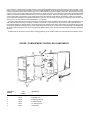
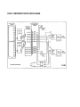
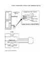
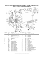
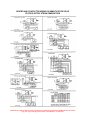
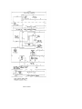
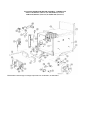
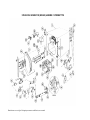
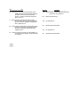
Cleveland Range
REPAIR MANUAL
Model No.
6/9CEM18/27/36/48
6/9CGM100/200/250/300
6/9CDM
6/9CSM
Cleveland Range, Inc.
UNITED STATES
1333 East 179th St.
Cleveland, Ohio 44110
Phone: (216) 481-4900 • FAX: (216) 481-3782
CANADA
Garland Commercial Ranges • 1777 Kamato Rd.
Mississauga, Ontario CN L4W 1X4
Phone: (416) 624-0260 • FAX: (416) 624-0623
FCS-05
INSTALLATION INSTRUCTIONS
for
STEAMERS, STEAMER/KETTLES,
MODULAR BOILER BASES, and
KETTLES ON BOILER BASES
CONVECTION
STEAMER with
KETTLE
MODULAR
BOILER
BASE
KETTLES ON
BOILER BASE
Cleveland Range, Inc.
UNITED STATES
1333 East 179th St.
Cleveland, Ohio 44110
Phone: (216) 481-4900 - Telex: 98-0546 • FAX: (216) 481-3782
CANADA
Garland Commercial Ranges • 1177 Kamato Rd.
Mississauga, Ontario CN L4W 1X4
Phone: (416) 624-0260 • FAX: (416) 624-0623
INSTALLATION INSTRUCTIONS FOR
STEAMERS, STEAMER/KETTLES, MODULAR BOILER BASES, and
KETTLES ON BOILER BASES
FOR YOUR SAFETY
Do not store or use gasoline or other flammable vapors
and liquids in the vicinity of this or any other appliance.
WARNING
Installation of this equipment must be accomplished by qualified installation personnel.
working to all applicable local and national codes. Improper installation of this product could
cause injury or damage.
Cleveland Range equipment is designed and built to comply with applicable standards for manufacturers. Included among those
certification agencies which have approved the safety of the equipment design and construction are: UL. A.G.A., NSF, ASME,
CSA, CGA, and others.
Cleveland Range equipment is designed and certified for safe operation only when permanently installed in accordance with
local and/or national codes. Many local codes exist, and it is the responsibility of the owner and installer to comply with these
codes.
In no event shall Cleveland Range assume any liability for consequential damage or injury resulting from installations which are
not in strict compliance with our installation instructions. Specifically, Cleveland Range will not assume any liability for damage
or injury resulting from improper installation of equipment, including, but not limited to, temporary or mobile installations.
INSTALLATION INSTRUCTIONS FOR ALL MODELS
1.
These instructions must be retained by the owner/user for future reference. Gas-fired boilers are only to be installed in
noncombustible areas that have provisions for adequate air supply. The term "boiler" will be used synonymously with "steam
generator."
WARNING
The flooring that will be directly under the boiler, must also be made of a noncombustible material.
2. Position: For proper operation and drainage, the equipment must be level. It should be placed next to an open floor drain. DO
NOT POSITION THE UNIT DIRECTLY ABOVE THE FLOOR DRAIN. Observe all clearance requirements to provide air
supply for proper operation, as well as sufficient clearance for servicing. The surrounding area must be free and clear of
combustibles. Dimensions and clearance specifications are shown on the specification sheet.
3. Install in accordance with local codes and/or the National Electric Code ANSI/NFPA No. 70-1987. Installation in Canada must
be in accordance with the Canadian Electrical Code CSA Standard C22.1. Equipment that is connected to electricity must be
grounded by the installer. A wiring diagram is provided inside the base cabinet
4- The drain line outlet discharges exhaust steam and hot condensate. Connect 11/2" IPS piping (or larger) to extend the drain line
to a nearby open floor drain. Up to two elbows and six feet of 11/2" IPS (or larger) extension pipe should be connected to the
drain termination. Drain piping extended six to twelve feet, or using three elbows, should be increased to 2" IPS. No more than
two pieces of Cleveland Range equipment should be connected to one common drain line. The maximum length of extension
from the drain termination should not exceed six feet and use no more than two elbows. The extension piping must have a
gravity flow and vent freely to the air. This drain outlet must be free-vented to avoid the creation of back pressure in the steamer
cooking compartments. To ensure a vented drain line. DO NOT, UNDER ANY CIRCUMSTANCES. CONNECT THE DRAIN
OUTLET DIRECTLY TO THE FLOOR DRAIN OR SEWER LINE. Do not run the drain line discharge into PVC drain piping
or any other drain piping material not capable of sustaining 180°F operation.
FAILURE TO OBSERVE THESE REQUIREMENTS CAN RESULT IN DAMAGE TO EQUIPMENT AND/OR THE POSSIBILITY OF INJURY
(Continued on next page)
• Direct-steam connected pressure steamers do not require a cold water connection, and therefore steps #5 and #6 do not
apply. Refer directly to step #7. A kettle fill faucet, if-so equipped, requires a hot and/or cold water connection. The data
contained in step #5 for cold water also applies to hot water.
5. Connect COLD water supply plumbing to the line strainer. (Never connect hot water to the boiler's water fill line strainer).
Constant flow pressure must be maintained between 35 and 60 psi, and not experience a pressure drop below 35 psi when
other appliances are used. If the water pressure exceeds 60 psi, a pressure reducing valve must be installed in the water supply
plumbing to reduce the water pressure to less than 60 psi. Locations and pressure data are shown on the specification sheet.
1/4" IPS plumbing is sufficient for water supply lines up to 20 feet in length, but water supply lines longer than 20 feet should
be at least 3/8" IPS. Rush water supply lines thoroughly before connecting them to the unit. Use water which is low in total
dissolved solids content and low in gas content to prevent internal scaling, pitting and corrosion of the steam generator, and
carry-over of minerals into the steam. Water which is fit to drink can still contain highly detrimental impurities.
NOTE: If equipped with a kettle and kettle water fill swing spout, 3/8" (10mm) hot and/or cold water connection(s) will be
required at the swing spout's Valve-6, Turn on the cold water supply to the unit. Ensure that the manual water valve, inside the
base cabinet. is open.
7. Connect the primary fuel supply in accordance with the following instructions. Location and other data are shown on the
specification sheet.
For Gas-Fired Steam Generators:
Post, in a prominent location, instructions to be followed in the event the user smells gas. This information shall be obtained
by consulting the local gas supplier. Install a sediment trap (drip leg) in the gas supply line, then connect gas supply piping to
the boiler's gas valve piping. GAS-FIRED EQUIPMENT IS DESIGNED FOR INSTALLATION ONLY IN NONCOMBUSTIBLE LOCATIONS. THIS INCLUDES THE FLOORING THAT WILL BE DIRECTLY UNDER THE
EQUIPMENT. Location, plumbing size, and pressure data are shown on the specification sheet. Boilers rated at less than
225.000 BTU require 3/4" IPS gas supply piping, and boilers rated at 225.000 BTU or more require 1" IPS gas supply piping.
Natural gas supply pressure must be between 4" -14" water column, and LP. gas supply pressure must be between 12" - 14"
water column . NEVER EXCEED 14" WATER COLUMN (1/2 psi) GAS PRESSURE. If the gas supply pressure exceeds
14'' water column, a pressure regulating valve must be installed in the gas supply plumbing to reduce the gas pressure to less
than 14" water column. Installation must be in accordance with local codes, or in the absence of local codes, with the National
Fuel Gas Code, ANSI Z223.1-1984. Installation in Canada must be in accordance with Installation Codes for Gas Burning
Appliances and Equipment B149.1 and B149.2. Use a gas pipe joint compound which is resistant to LP gas. Turn the gas
valve's control knob to "on" (the word "on" on the knob will be opposite the index on the valve's body). Test all pipe joints for
leaks with soap and water solution. Never obstruct the flow of combustion and ventilation air. Observe all clearance
requirements to provide adequate air openings into the combustion chamber. The appliance and its individual shut-off valve
must be disconnected from the gas supply piping system during any pressure testing of that system at test pressures in excess
of 1/2 psi (14" water column or 3.45 kPa). The appliance must be isolated from the gas supply piping system at test pressures
equal to or less than 1/2 psi (14" water column or 3.45 kPa). A permanent 115 volt electrical connection is required at the
junction box. The junction box location is shown on the specification sheet. The unit must be electrically grounded by the
installer.
For Electric-Powered Steam Generators:
Connect electric power location and date are shown on the specification sheet. Provide connection as required by your unit:
either directly to the single contactor, or to the terminal block (when equipped with multiple contactors). Electric supply must
match power requirements specified on the data plate inside the base cabinet. The copper wiri
ng must be adequate to carry the required current at the rated voltage. A separate fused disconnect switch must be supplied and
installed. The unit must be electrically grounded by the installer.
For Steam Coil Steam Generators:
Connect steam supply piping to the input side of the steam coil. Location and pressure data are shown on the specification
sheet- Incoming steam pressure must be regulated between 35 and 45 psi. A 3/4" strainer, equipped with a 20 mesh stainless
steel screen, must be supplied and installed at the incoming steam connection point Rush the steam line thoroughly before
connecting it to the boiler. To ensure an adequate volume of steam, the branch steam supply line must be 3/4" IPS minimum.
Connect the inverted bucket trap to the outlet end of the steam coil. Fill the trap with water before installing it. A permanent
115 volt electrical connection is required at the junction box. The junction box location is shown on the specification sheet.
The unit must be electrically grounded by the installer.
For Direct-Steam-Connected Steamers/Kettles:
Connect steam supply piping to the input side of the line strainer. Location and pressure data are shown on the specification
sheet. Rush the steam line thoroughly before connecting it to the steamer. To ensure an adequate volume of steam. the branch
steam supply line must be 3/4" IPS minimum. (Direct-steam-connected kettles require 1/2" IPS pipe if the kettle's total
capacity is 20 gallons or less, and 3/4" IPS pipe if the total capacity exceeds 20 gallons.) A permanent 115 volt electrical
connection is required at the junction box. The junction box location is shown on the specification sheet. The unit must be
electrically grounded by the installer. (Note: pressure steamers equipped with strictly manual steam and drain valves do not
require an electrical connection.)
(Continued on reverse side)
(Continued)
8. Press the top of the power on-off rocker switch. The red indicator light in the switch will come on and the boiler will
begin to fill with water.
• Direct-steam-connected steamers are not equipped with self-generating boilers or "steam" switches. Therefore, these models
do not require the 5-minute boiler water fill time, nor is it necessary to push a "steam" switch to produce steam, as indicated
in step #9. As soon as the pressure gauge on the control panel registers 10 psi (5 psi for pressure steamers), preheating may
begin. If you are operating a direct-steam-connected steamer, steps #9 and #10 do not apply. Refer directly to step #11.
9. After about five minutes, the amber light in the "steam'' switch will glow, indicating the water has reached a safe operating
level in the boiler. The "steam" switch can now be pressed (momentarily) in order to produce steam in the boiler. This will
activate the energy source (electric heaters, gas burners, or steam solenoid valve), and the amber light will go out. The energy
source cannot be activated until the boiler contains sufficient water, indicated by the amber light. The "steam" switch must be
pushed to re-start the steamer after it is shut off for any reason (including a momentary power interruption). Do not attempt to
start or operate this appliance during a power failure. Whenever the amber light is illuminated, the healer, steam supply, or
burners are off, and no steam is being generated- (Note: for units containing gas-fired boilers only: if the burners fail to ignite
in four seconds, a safety circuit will de-energize the system. In this event, momentarily press the power switch to the "off"
position, then back to the "on" position. The "steam" switch amber light should be on. Wait 5 minutes, then press the "steam"
switch to start the burner ignition cycle once again.)
10. Check to ensure that the water in the boiler's sight gauge glass automatically stays about 1/3 full when the boiler is started up
and operated.
11. Check to ensure that the steam pressure gauge registers 10 psi (5 psi for pressure steamers).
The steam pressure is factory-adjusted to provide the proper pressure. In some cases, however, the factory setting may shift due
to shaking in transit, and resetting will be required after installation. Proper adjustments and maintenance procedures are
detailed on a separate data sheet entitled "Steam Pressure Adjustments." Adjustments should be made only by qualified service
personnel. The factory pressure settings shown in the accompanying chart should never be exceeded.
12. When the installation is complete and free of leaks, refer to the Operating Procedures page, in order to check for proper
operation of the unit.
GAUGE PRESSURE R
READING WITH NO STEAM PLOW (STOIC PRESSURE)
Self-Contained Steam Generator Gas or Electric
Self-contained Steam Coil Generator
Steamer's
Pressure
Reducing Valve
Operating
Pressure Switch
High Limit
Safety Pressure
Switch
Operating
Pressure
Switch
N/A
5 psi
10 psi
5psi
N/A
5 psi
10 psi
5 psi
10 psi
15 psi
5 psi
High Limit Safety
Pressure Switch
Direct-Connect (To "House" Steam
Supply)
Steam Supply
Pressure Range
Steamer's
Pressure
Reducing Valve
Steam Supply
Pressure Range
i
30-45 psi
N/A
N/A
10 psi
30-45 psi
5 psi
12-45 psi
i
30-45 psi
5 psi
12-45 pa
Equipment
Steam Generator Only
5 psi
Pressure Steamer
10 ps
Pressure Steamer With Any
Kettle(S)
5 ps
Steam Generator Only 10 psi
N/A
10 psi
15 psi
10 psi
15 psi
30-45 psi
N/A
N/A
Kettle Only —At
N/A
10 psi
15 psi
N/A
N/A
N/A
N/A
5-45 psi
Convection Steamer with or
Without Kettles
N/A
10 psi
15 pa
10 psi
15 psi
35-45 psi
10 pa
15-45 OS
i
10 ps
'Kettles are to be connected to the "house" steam supply
2SO-TR (R2)0388
Data Sheet 260-TY
CLEVELAND CONVECTION STEAMER (MODEL C) OPERATING INSTRUCTIONS
Operation of the Cleveland Convection Steamer is very easy Each operator should read and understand the following procedures to effectively
start, operate, and shutdown the steamer each day.
Start-up and Preheat:
1- Check the cooking compartments to ensure that the steam tubes and drain screens are in place and secure. Check inside the steamer's base
cabinet to ensure that the manual drain valve is closed and the manual water s upply valve is open.
2. Press the top of the power on-off rocker switch located at the lower left of the control panel, under the steam pressure gauge. The red indicator
Iight in the switch will come on and the boiler will begin to fill with water.
• Direct-steam-connected steamers are not equipped with self-generating boilers or "steam" switches. Therefore, these models
do not require the 5 minute boiler water fill time. nor is it necessary to push a "steam" switch to produce steam, as indicated in
step #3 below. As soon as the pressure gauge on the control panel registers 10 psi. preheating may begin. If you are
operating a direct-steam-connected steamer. "skip" step #3. and refer directly to step #4.
3. After about five minutes, the amber light in me "STEAM" switch will glow, indicating the water has reached a safe operating level in the boiler.
The "STEAM" switch can now be pressed (momentarily) in order to produce steam in the boiler. This will activate the energy source (electric
heaters. gas burners, or steam solenoid valve), and the amber light will go out The energy source cannot be activated until the boiler contains
sufficient water, indicated by the amber light. The "STEAM" switch must be pressed to restart the steamer after it is shut off for any reason
(including a momentary power interruption). No attempt should be made to operate the equipment during a power failure. Whenever the amber
Iight is illuminated, the heaters, steam supply, or burners are off, and no steam is being generated. (Note tor steamers containing, gas-fired
boilers only if the burners tail to ignite in four seconds, a safety circuit will de-energize the system. In this event, momentarily press the power
switch to the "off" position, then back to the "on" position. The "STEAM" switch's amber light should be on. Wait 5 minutes, then press the
"STEAM" switch to start burner ignition cycle once again.) In about 20 minutes the steam pressure gauge on the control panel should register
10 psi.
4. You can now preheat the cooking compartment(s). Cooking compartments should always be preheated before cooking.
NOTE: With a steamer/kettle combination, if both must be used at the same time, always heat the kettle first When kettle contents begin to
simmer and steam pressure returns the steamer compartments may be preheated.
5. To preheat close the compartment door by gently swinging it shut Set the electronic digital timer for one minute, in accordance with the
following timer setting instructions. It will be several minutes before the time display begins to count down. When the preheating is completed,
me steam will automatically shut off and a tour second alarm will sound.
Timer Setting:
Each Convection Steamer compartment is equipped with an independent electronic digital timer, which has a maximum setting of 99 minutes.
Each timer is connected to a temperature sensing device in the cooking compartment. THIS SENSOR WILL ALLOW THE TIMER TO COUNT
DOWN ONLY
will use, as the timer automatically compensates for food product defrosting and/or heat-up time.
The timer can be set when the "COOKING TIME" display shows "00" (double zeros) which are illuminated continuously (not flashing). The two
small. square pads below the timer display are pressed to set the timer. Press 1 to set one to nine (and zero) minutes for units digits (single
minutes). Press 10 to set ten to ninety minutes for ten's digit (multiples of ten minutes). Pressing continuously on either pad causes the digits to
change at a rate of digits per second. If you pass the correct digit, continue pressing the pad. The display will cycle from "9" back to "O." then
continue upward again.
The timer is activated (and steam enters the cooking compartment} when the "START/ cancel pad is pressed. Red LED- lights glow in the upperleft comer of the pad and the lower-right corner of the time display when the timer is activated. REMEMBER, THE TIMER WILL BEGIN TO
COUNT DOWN ONLY AFTER THE COMPARTMENT REACHES PROPER COOKING TEMPERATURE. When the timer is counting down, the
red LED. light continuously flashes on and off at the lower-right corner of the display. Once the pre-set time has counted down to zero, an alarm
will sound for four seconds and the timer display will continuously flash "00" until the "start/CANCEL" pad is pressed. Once the timer is activated,
the time cannot be changed unless the "start/CANCEL" pad is pressed. Once pressed. the pad's LED will go out, any remaining time in the timer
will be cancelled, and the display will show "00 — not flashing, A new time setting can now be entered into the timer display.
EXAMPLE: To cook for 14 minutes: Press the "start/CANCEL" pad to be sure the timer display shows "00" and is not flashing. Press the 10 then
release it when the "1" appears in the display. Press the 1 and release it when the "4" appears in the display. Press the "START/cancel pad to
start the timer (note the illuminated red LED.'s in the pad and the time display). When the display counts down to zero. a tour second alarm will
sound, and the display will flash "00" (the LED.'s will go out}. Press the "start/CANCEL" pad to reset the timer, shown by continuously illuminated
"00" in the display (not flashing).
Automatic Cooking Operation:
To cook, place a pan of food in the compartment, set the desired cooking time and press the "START/ cancel" pad The timer will delay.
automatically compensating lor defrosting and/or food product heat-up time. If you have set the timer at 10 minutes, it may in fact take 11 on 2
minutes for the set
When the display counts down to zero. the four second alarm will sound, and the display will flash "00" (the LED's will go out). Press the
"start/CANCEL" pad to reset the timer, shown by continuously illuminated "00" in the display.
Manual Cooking Operation:
If a cooking cycle longer than 99 minutes is desired, do not use the timer. Just press the "MANUAL OPERATION" pad. located below the timer, to
start the flow of steam. You must press the pad again to shut off the steam. A red LED light in the upper-left comer of the pad illuminates nates
when the manual mode is activated and steam is flowing into the cooking compartment. THE TIMER CAN BE USED DURING THIS TIME. IT WILL
OPERATES AS STATED. EXCEPT IT WILL NOT TURN OFF THE STEAM AFTER THE ALARM SOUNDS.
The door may be opened for food inspection anytime during the cooking cycle, but KEEP HANDS OUT OF THE COOKING COMPARTMENT TO
PREVENT BURNS. Optimum steam heat transfer, and therefore a higher quality food product is achieved when shallow perforated uncovered
pans are used.
Boiler Shutdown:
The red-lighted power switch must be shut off for 3 minutes a minimum of once every 8 hours to automatically drain highly mineralized water from
the boiler, which reduces the formation of scale.
Data—Sheet—26EO (R1)
CONVECTION STEAMER MECHANICAL COMPONENTS
(Solid State Model "C" with Touch Control Timer Panel)
REFERENCE NUMBER
PART NUMBER
DESCRIPTION
1
2
3
4
5
6
7
8
9
10
11
12
44090
44098
68214
07138
04171
14687
68508
44087
44088
02089
69629
44167
58113
70638
19152
40878
58178
58179
40883
40884
19552
40783
15203
69298
69233
41423
Inner Door Assembly
Gasket Retainer Plate
Inner Gasket Retainer Plate
Gasket
Inner Door
Knurled Finger Nut. 1/4-20
Inner Door Mounting Stud
Outer Door Assembly
Outer Door Weldment
Bushing (2 required)
Door Spring
Door Latch Assembly
Door Latch (less plastic insert & screws)
Plastic Insert (not shown)
Pivot Screw (2 required)
Door Catch Assembly
Upper Hinge Bracket (lower if door is hinged right
Lower Hinge Bracket (upper if door a hinged right)
Upper Hinge Pin and Retainer (lower if door a hinged right)
Lower Hinge Pin and Retainer (upper if door is hinged right)
Spacer
Steam Tube
"0" Ring (4 required)
Drain Screen (After Dec. 1. 1983)
Drain Screen (Before Dec. 1. 1983)
Slide Rack
13
14
15
16
17
18
19
20
21
22
CLEVELAND RANGE, INC., 1333 EAST 179th ST., CLEVELAND, OHIO 44110
Manufacturer reserves right of design improvement or modification, as warranted.
LITHO IN U.S-A.
Data Sheet 261
CONVECTION STEAMER ELECTRICAL COMPONENTS
(Solid State Model "C" with Touch Control Timer Panel
REFERENCE NUMBER
PART NUMBER
DESCRIPTION
1
2
3
45005
20479
16652
Control Panel (Membrane Switch)
Solid State Timer
Power Supply Board
4
5
6
52595
56228
03002
Instrument Panel Enclosure
Instrument Panei Frame
9" Cable Assembly
7
8
9
03003
08135
19993
14" Cable Assembly
Wire Harness
DPDT Power Switch
10
11
12
19994
19972
44168
SPST Momentary Contact Reset Switch
Thermostatic Switch
Terminal Block 2 pole
13
19992
DPDT Rocker Switch Emergency Bypass
CLEVELAND RANGE, INC., 1333 EAST 179th ST., CLEVELAND, OHIO 44110
Manufacturer reserves right of design improvement or modification, as warranted.
LITHO IN U.S.A.
CONVECTION STEAMER PIPING COMPONENTS
(Solid State Model "C" with Touch Control Tuner Panel)
REFERENCE NUMBER
1
2
3
4
5
6
7
8
9
10
11
12
13
14
15
16
17
PART
NUMBER
DESCRIPTION
07168
22218
15455
13301
22226
22224
20559
06230
14555
02139
05227
Pressure Gauge
Water Solenoid Valve
Plow Regulator. 1/ 2 GPM
Steam Manifold
Air Vent
Steam Solenoid Valve
Thermostatic Trap
Reducing Bushing for Nozzle
Nozzle. Jet, Steam Condenser
1" "Y"
1" Street Elbow
56519
70743
70742
14481
03180
13252
Compartment Drain Fitting (2 holes)
Tubing, 39" long
Tubing, 28" long
Combination Hose Fitting (no holes)
Hose Clamp
Drain Manifold
CLEVELAND RANGE, INC., 1333 EAST 179th ST., CLEVELAND, OHIO 44110
Manufacturer reserves right of design improvement or modification. as warranted.
LITHO IN U.S.A.
SERVICE GUIDE FOR CLEVELAND CONVECTION STEAMER SOLID STATE
COMPARTMENT CONTROLS
Read the following instructions to familiarize yourself with the solid state timer components and their functions. Once familiar with the
operation, refer to the troubleshooting guide when on the job site (to diagnose the problem), then refer back to the instructions for specific
tests.
The solid state compartment control system for Cleveland Range Steamers is designed for easy service. No special tools or technical
training is required to troubleshoot and repair these controls. A suggested list of required tools is as follows:
1. Screwdriver (blade type)
2. 1/4" or 5/16" nut driver
3. V.O.M. or multimeter
Refer to Figures #1 and #2. The system contains 4 basic components: (1) control pane! (45005). (2) two solid state timers (20479), (3)
power supply board (1 6652). (4) interconnecting cables and harness (03002,03002,08135). Each of these four parts will be discussed in detail.
Solenoids and manual bypass switches will not be covered in this guide. All of these parts, except #08135, are assembled in one enclosure
(40833) that can be removed easily from the front of the steamer.
The Convection Steamer cooking compartments are controlled by a low voltage solid state system that provides both
timed and manual operation of the cooking compartments-All wiring connections to the timer system are provided through a multipin
connector that is part of the power supply board. The wiring harness is equipped with the mating pan for the connector.
The power supply board provides 24 VDC to power the output relay coils and the alarm. 5 VDC for the timer and logic power, and 5.5
VAC to provide clock pulses to the timers. The stepdown transformer is mounted to the power supply board. Also on this board are two DPDT
relays (one for each compartment) which are used to switch 120 VAC on and off to the compartment steam and water solenoid valves. A 4second piezo type alarm mounted on the power supply board is used to signal the steamer operator at the end of the cooking cycle.
Each solid state timer is wired to the power supply board by a cable assembly and to the control panel by a ribbon connector. These timer
boards are equipped with LED displays to indicate cooking time and operating mode. Compartment thermostatic switches are wired to the
timers through the power supply board and cable assemblies, and operate at 5 VDC. These thermostatic switches (normally open. then close at
193° F) are used to activate the timers when the compartments reach cooking temperature. Each timer board and thermostatic switch
independently controls a single compartment
The control panel contains the membrane type switches which provide 5 VDC command signals to the timer boards. The metal backing
plate is used to mount the two timer boards-Two DPDT emergency bypass switches (one for each compartment) are provided, with the switch
"commons" connected to the load. Both switches should normally remain in the "run" position. With a switch in the "run" position, the
appropriate steam and water solenoid valves will be operated by the control system described above. In the event of a failure in the solid state
compartment control system, the system can be bypassed by placing one or both switches in the "bypass" position. With a switch in the bypass
position, the appropriate steam and water solenoid valves will be energized continuously. Each switch can be used to manually operate a
cooking compartment until the control system is repaired.
CONTROL PANEL (MEMBRANE SWITCH)
The control panel (45005) consists of a membrane switch panel bonded to a stainless steel backing plate. This metal plate is also used to
mount the two solid state timer boards (20479). All control panel switches are normally open momentary contact, pressure sensitive
membrane type switches. All control panel switches operate at 5 VDC. Each switch is used to provide a command signal to the timer boards.
The switch circuitry for each compartment is separate from the other compartment. Two separate connectors, (one for each compartment),
are used to connect the switches to the timer boards. This separation allows one compartment to work even if control switches of the other
compartment are damaged. If pressing a control switch of one compartment causes the control of the other compartment to respond, the
control panel (membrane switch) is defective or damaged.
The switch panel can be tested individually by continuity testing. Refer to figure #3. With none of the switches being pressed, there should
be no continuity between any two pins of the connector. When checking an individual switch, there should be continuity between the common
pin and the designated pin of the switch only when the switch is
pressed. Check to be sure that no other pins show continuity to "common" except the pin of the switch being pressed.
CAUTION: When checking continuity, it is best to use a VOM or multimeter, as higher lamp currents of some
continuity testers may damage the switch contacts. Resistance reading should be less than 50 ohms. DO NOT
use AC line voltage or DC voltages above 5 VDC.
Check for damaged or abraided ribbon connectors that may cause shorting to the metal of the control enclosure If
necessary, insulate the ribbon by placing black electrician's tape along the tracer side of the ribbon connector
SOLID STATE TIMER BOARD
Complete testing of the timer board in the kitchen may be impractical. However, knowing the functions which are
exclusive to the timer board, accurate diagnosis of failures can be made.
The following functions are performed by each timer board:
1 Cooking time entry and storage.
2 Display of cooking time remaining.
3. Count down (timing) when the compartment thermostatic switch is closed.
4 Energizing the output relay during cooking cycles (manual and timed).
5. Manual on/off control of the compartment.
6. Sounding the alarm for four seconds at the end of the cooking cycle.
7. Display of operating mode (manual and/or timed).
8. Flashing display digits after the end of the timed cooking cycle.
Although the other components in the control system are necessary for proper operation, they are only support or
interface hardware for these timer boards.
All logic and operating sequences are the direct functions of the timer boards.
Generally, failures that affect the operation of both compartments are not associated with the timer boards, as each
timer board independently controls a single compartment. When there is trouble with the operation of one compartment
control only. simple tests made by switching wire cables at the power supply board, or swapping timer boards, are
helpful in pinpointing a defective unit. As an example, if a serviceman found that the upper compartment's controls did
not switch on the solenoid valves for that compartment, he may proceed as follows. First with the steamer power off,
the interconnecting cables (03002 and 03003) could be interchanged at the power supply board. With the steamer's
power restored, if the same compartment failed to operate, this would indicate a problem with the power supply board,
wire harness (08135), or solenoid valves. If the symptoms changed from the upper compartment to the lower, then the
fault is in the timer board or control panel. The control panel may be tested individually as described in the "Control
Panel Section, or it can be tested by swapping the timer boards- To do this, interchange the upper and lower timer
boards and connect the wire cables in their original, correct order. If, after changing the boards (and installing cables
correctly), the upper compartment still does not work, then the control panel is at fault On the other hand. if the
symptoms changed from the upper compartment to the lower, then the fault is in the timer board now mounted on the
bottom. Due to the simple wiring and mounting design of the solid state controls, these types of tests can often be done
faster than testing with meters or special test set-ups.
POWER SUPPLY BOARD
The basic function of the power supply board is as an interface between the 120 VAC control system of the steamer
and the low voltage (5 VDC) circuits of the timers All connections to the board are provided by polarized multi-pin cable
or harness connectors
A simplified schematic of the board is shown in figure #4. The power supply, including transformer, is
powered by 120 volts AC. and provides 3 output voltages:
1 5 volts DC to power the solid state timers and digital displays. 2- 24
volts DC to power output relay coils and the alarms. 3. 5.5 volts AC to
provide clock pulses to the timers.
The 5 volt and 24 volt DC outputs of the power supply are equipped with LED indicators to aid in troubleshooting. In
normal operation, these LED's should be illuminated any time power (120 VAC) is supplied to the board. If there is no
output voltage from the 5 volt DC and/or 24 volt DC supplies, then the corresponding LED will not be fit. In addition,
both the 5 volt and the 24 volt DC supplies are protected against short circuits. If there is a short circuit, the voltage
regulator of the affected supply will shut down and the indicating LED for that supply will not be fit. This feature can be
useful in determining the location of a short circuit. Disconnect the cable connectors at the power supply board to
determine if the
short circuit is in a timer board or a cable connector. It the LED illuminates when the cable connectors are disconnected. a timer
board or cable connector is snorted. NOTE: The power supply regulators are thermally protected and may be overheated. In this
case, the regulators require time to reset to their "on" condition before they allow the LEDs to illuminate.) Reconnecting the cable
connectors one at a time will indicate which timer board (or cable) is snorted, as the LED will not be lit when the defective board's
cable is reconnected To determine if the short circuit is in a cable connector, disconnect each cable from the timer boards, then
connect each cable, one at a time, to the power supply board. The LED wilt not be lit when the defective cable is reconnected.
The actual output voltages may be measured between "Common" and the cable connector pins. as shown in figure #4. (pin # = 5
VDC. pin #7 = 5.5 VAC. alarm's solder joint labeled "+1" = 24 VDC).
The output relays are used to switch 20 volts AC on and off to the steam and water solenoid valves of the compartments. The
relay coils (24 VDC) need only a "common" connection to operate. In normal operation me "common" path is provided by the
timer boards (20479). To test the relays, shut off the power to the steamer at the main on/off switch. Disconnect the wiring cable
assemblies (03002 and 03003) from the power supply board, and remove the control panel- Connect a jumper from pin #2 to pin
#4 of each cable connector (on the power supply board). Restore power to the steamer. The relays should close upon application
of power.
A similar test can be used to test the alarm. Jumping pin #3 to pin #4 of either cable connector will cause the alarm to sound.
FIGURE 1 COMPARTMENT CONTROL BOX COMPONENTS
REFERENCE
NUMBER
PART
NUMBER
DESCRIPTION
1
45005
Control Panel (Membrane Switch)
2
3
20479
16652
Solid State Timer
Power Supply Board
4
03002
9" Cable Assembly
4
4
03003
08135
14" Cable Assembly
Wire Harness
FIGURE 2 COMPARTMENT CONTROL WIRING DIAGRAM
FIGURE 3 COMPARTMENT CONTROL PANEL (MEMBRANE SWITCH)
SAME FOR BOTH COMPARTMENTS
FIGURE 4 POWER SUPPLY BOARD SIMPLIFIED SCHEMATIC
PIN
CON 2 & CON 3
PIN NO.
CON 1
1
+5VDC SUPPLY
1
120VAC
2
RELAY OUT
2
120 VAC
34
ALARM OUT 5 AND 24 VDC COMMON
3
UPPER COMPARTMENT
4
UPPER COMPARTMENT
5
LOWER COMPARTMENT
6
LOWER COMPARTMENT
7
NO CONNECTION
8
NO CONNECTION
9
UPPER THERMOSWITCH
10
UPPER THERMOSWITCH
NO.
56
7
POLARIZED KEY THERMOSWITCH
5.5 VAC
1
1
12
LOWER THERMOSWITCH
LOWER THERMOSWITCH
TROUBLESHOOTING CHART FOR
CLEVELAND CONVECTION STEAMER SOLID STATE
COMPARTMENT CONTROLS
SYMPTOM
Both timers do not operate. There are no
lights or sounds.
CAUSE
REMEDY (Sec Text)
120 VAC power is not connected to the
power supply board.
Check the wiring from the 120 VAC supply to
the board (including the wire harness). Repair
or replace as necessary.
The 5 VDC circuit is short-circuited
Repair as required or replace the shorted timer
board, power supply board, or cable assembly.
The5.VD.C-power supply is inoperative
Replace the power supply board
Poor wiring connections from the power
supply board to the timer boards.
Check the cable assemblies and connections.
Repair or replace as necessary.
The 24 VDC circuit is short-circuited
Repair as required or replace the shorted power
supply board
Replace the power supply board
Both timers appear to operate, but steam does
The 24 VDC power supply is inoperative
not flow into either compartment and the
alarm does not sound.
A compartment operates in only one mode.
either timed or manual
One compartment will not operate in either
mode, timed or manual, and the mode
indicator LED’s do not light.
Poor wiring connections from the timer
boards to the power supply board.
Check the cable assemblies and connections.
Repair or replace as necessary.
Damaged or inoperative control panel
(membrane switch)
Replace the control panel.
Damaged or inoperative timer board.
Replace the timer board
Damaged or inoperative control panel
(membrane switch or ribbon connector).
Replace the control panel.
Poor wiring connections from the power
supply board to the ti mer board (of the
affected compartment).
Check the cable assembly and connections (of
the affected compartment). Repair or replace as
necessary.
Damaged or inoperative timer board
Replace the timer board
Poor wiring connections from the power
supply board to the solenoid valve.
Check me wire harness and connections. Repair
or replace as necessary-
A timer appears to operate, but steam does not
Damaged or inoperative relay on the power
flow into the compartment
supply board.
Replace the power supply board.
Damaged or inoperative solenoid valve-
Repair or replace the solenoid valve.
Damaged or inoperative emergency by-pass
switch.
Replace the switch
Damaged or inoperative timer board
Replace the timer board
SYMPTOM
CAUSE
REMEDY (See Text)
A timer does not count down when the
compartment is hot
The thermostatic switch is not closing.
Inoperative timer board.
There is no 5-5 VAC signal to the timer
board.
Poor wiring connections from the thermal
switch to the timer board.
Replace the thermostatic switch
Replace the timer board-Check the power
supply board, cable assemblies, and
connections. Repair or replace as necessary.
Check the cable assemblies, wire harness, and
connections. Repair or replace as necessary.
Pressing a control panel switch pad for one
compartment causes the controls of the other
compartment to respond.
Damaged or inoperative control panel
(membrane switch or ribbon connector).
Replace the control panel.
The timer display digits appear incomplete or
the indicator LED’s do not light.
Damaged or inoperative timer board The timer
board is water-soaked.
Replace the timer board. Dry the timer board.
The alarm sounds continuously (sound could be The power supply board is water soaked.
a low-pitched whistling).
The alarm is snorted.
Damaged or short-circuited cable assembly.
Damaged or inoperative timer board.
Dry the power supply board.
Replace the power supply board.
Check the cable assemblies and connections.
Repair or replace as necessary
Replace the timer board.
The flow of steam into a compartment will not The emergency by-pass switch is in the "on"
shut off
position. Dirt or foreign material is jammed in
the solenoid valve.
Damaged or short-circuited timer board.
Turn off the switch Repair or replace the
solenoid valve. Replace the timer board-
The time entry will not hold in the display - one Damaged or inoperative control panel
or both display digits change continuously
(membrane switch or ribbon connector).
Replace the control panel.
When the "Start/Cancel" pad or "Manual
Operation" pad is pressed, the compartment
steam solenoid valve opens, then closes
immediately.
Insufficient supply voltage (120 VAC nominal) Check the building's supply voltage to the
to the timer control box.
equipment and check the wiring to the timer
control box. Repair as necessary.
Cleveland Range, Inc.
UNITED STATES
1333 East 179th St. Cleveland, Ohio 44110
Phone: (216) 481-4900 • Telex: 98-0546 • FAX: (216) 481-3782
CANADA
Garland Commercial Ranges
1177 Kamato Road
Misassaugha, Ontario, Canada L4W1X4 Phone:
(416) 624-0260 • FAX: (416) 624-0623
ELECTRIC STEAM GENERATOR (BOILER) ASSEMBLY - 2 PROBE TYPE 18 KW, 27 KW,
36 KW, & 48 KW (2, 3, & 4 HEATER ELEMENTS)
(OPTIONAL)
REFERENCE
NUMBER
PART
NUMBER
DESCRIPTION
1
43894
Electric Boiler Shell only. with legs. hand hole
plate assembly. mounting studs for 3" sauareflanged heater elements
Electric Boiler Shell (43894) above, also includ
ing sight gauge, two probes and extensions with
cover box.
Hand Hole Plate Assembly including Bar. nut.
and gasket.
Hand Hole Plate only
Hand Hole Gasket. 4- x 6' oval
Probe
Probe Extension Set (set of two)
Probe Cover Box
Water Gauge Set with Glass
Fibre Washer (2 required)
Gauge Glass Washer (2 required)
Gauge Glass Only. 6" long
Heater. 9 KW. 206 volt. 3 phase
Heater. 9 KW. 220/240 volt 3 phase
Heater. 9 KW. 440/480 volt. 3 phase
Heater. 9 KW. 600 volt. 3 phase
Heater. 9 KW. 208 volt 1 phase
Heater. 9 KW. 220/240 volt- 1 phase
Heater. 9 KW. 440/480 volt 1 phase
Heater. 9 KW. 600 volt. 1 phase
Heater. 12 KW. 208/220 volt. 3 phase
Heater. 12 KW. 230/240 volt 3 phase
Heater. 12 KW. 440/480 volt 3 phase
Heater. 12 KW. 600 volt 3 phase
Heater. 12 KW. 208/220 volt. 1 phase
Heater. 12 KW. 230/240 volt. 1 phase
44149
2
40421
2a
3
4
5
6
7
43748
07106
40462
101466
52305
40445
07108
23132
07302
08235
08236
08237
08234
08241
08242
08243
08244
08165
0 8166
08167
08163
08214
08215
8
9
REFERENCE
NUMBER
10
11
12
13
14
IS
16
17
18
19
20
21
22
23
24
25
26
27
28
29
30
31
32
33
34
35
36
PART
NUMBER
DESCRIPTION
08216
08217
07128
16546
22131
22130
19947
03509
03506
23198
03524
03525
44168
03202
20478
20535
22102
03276
22223
19870
03277
77771
13252
45006
41943
05253
02623
19995
19993
19994
07167
Heater. 12 KW. 440/480 volt 1 phase
Heater. 12 KW. 600 volt. 1 phase
Heater Gasket
3" Block-Off Plate
15 psi Safety Valve
8 psi Safety Valve
Pressure Switch
Contactor. 50 amp
Contactor. 75 amp
Control Board, water level and LWCO
Relay
Relay Socket
Terminal Block. 2 pole
Circuit Breaker. 1 amp
Interval Timer. 3 minute
Transformer. 150 VA
Check Valve, ¼”
1/4" " Ball Valve, water supply shut-off
Solenoid Valve, water feed
Line Strainer. 1/4"
¼" Ban Valve, manual drain
Solenoid Valve, boiler drain
Drain Manifold
Low Water Cut-off Assembly (California only)
LWCO Mounting Plate (California only;
Brass Street Elbow (California only)
Reducing Bushing 1\2" - V1/4" (California only;
Float Switch. LWCO (California only)
DPDT Power switch
SPST Momentary contact reset switch
Pressure gauge. 0-30 psi, 1 ½”
Manufacturer reserves right of design improvement or modification, as warranted
HEATER AND CONTACTOR WIRING SCHEMATICS FOR SOLID
STATE ELECTRIC STEAM GENERATORS
Manufacturer reseWe are aware of the poor quality and are making arrangements with the Manufacturer for a better
copy.rves right of design improvement or modification, as warranted.
Electric Models
We are aware of the poor quality and are making
arrangements with the Manufacturer for a better
copy.
Electric Models with Secondary Low Water Cutoff Built to California Code
GAS STEAM GENERATOR (BOILER) ASSEMBLY - 2 PROBE TYPE
SMALL: 100,000 BTU (2 Burners) & 200,000 BTU (4 burners)
LARGE: 250,000 BTU (5 burners) & 300,000 BTU (6 burners)
Manufacturer reserves right of design improvement or modification, as warranted.
GAS STEAM GENERATOR (BOILER) ASSEMBLY - 2 PROBE TYPE
SMALL: 100,000 BTU (2 Burners) & 200,000 BTU (4 burners)
LARGE: 250,000 BTU (5 burners) & 300,000 BTU (6 burners)
REFERENCE
NUMBER
PART
NUMBER
DESCRIPTION
43898
Small boiler shell only (100.000/200.000 BTU). with legs.
studs, hand hole plate assembly and top flue bracket.
43899
44173
44172
Large boiler shell only (250.000/300.000 BTU). with legs.
studs, hand hole plate assembly, and top flue bracket.
Small boiler shell (43898) above. also including insulation
panels, top flue collector with insulation. sight gauge. two
probes and extensions with cover box.
REFERENCE
NUMBER
PART
DESCRIPTION
NUMBER
44156
5-burner rear burner support
44157
6-burner rear burner support
22130
Safety valve. 8 psi
22131-
Safety valve. 15 psi
16
19947
Pressure switch
17
22228
Gas control valve, natural gas. small boiler
(100,000/200,000 BTU)
22230
Gas control valve. natural gas, large boiler
(250/300.000 BTU)
22231
Gas control valve. L.P. gas. small and large boilers
(100,000/200,000 and 250.000/300.000 BTU)
15
Large boiler shell (43899) above. also including insulation
panels, top flue collector with insulation, sight gauge, two
probes and extensions with cover box-
2
40421
Hand hole plate assembly including bar. nut and gasket.
18
44169
Ignitor cable
2a
43748
Hand hole plate only
19
44096
Ignitor box assembly with ignitor
3
07106
Hand hole gasket 4" x 6" oval
20
05101
Ignitor electrode
4
40462
Probe
21
5
101466
Probe extension set (set of two)
40918
40920
Gas manifold. 2 -burner
Gas manifold, 4 -burner
6
52305
Probe cover box
40921
Gas manifold. 5 -burner
7
40445
Water gauge set with glass
40922
Gas manifold. 6 -burner
07108
Fibre washer (2 required)
22
52602
Manifold alignment bracket
23132
Gauge glass washer (2 required)
23
19632
Orifice holder
8
07302
Gauge glass only. 6" long
24
15453
Burner orifice, natural gas
9
44043
Left side insulation panel assembly
15450
Burner orifice. L.P. gas
440431
Left side insulation panel assembly for L.P. gas 100,000/200,000 BTU boiler only
25
02497
Burner
26
03546
Spark ignition control module
44042
Right side insulation panel assembly
440421
Right side insulation panel assembly for LP. gas 100.000/200.000 BTU boiler only
27
2S
20528
20478
24 volt transformer
Internal timer. 3 minute
29
44164
Terminal block. 4 pole
42398
Top flue collector with insulation, for small boiler
(100.000/200.000 BTU)
30
03525
Relay socket
31
03524
Relay
32
33
23198
22102
Control board, water level and IWCO
Check valve. 1/4""
10
11
42399
13
42360
Internal flue riser assembly for small boiler (100,000/200,000
BTU)
34
03276
1/4" Ball valve, water supply shut off
42361
Internal flue riser assembly for large boiler (250.000/300.000
STU)
35
36
22223
19870
Solenoid valve, water feed
Line strainer. ¼"
44134
2-burner front baffle asse mbly - natural gas
37
03277
3/4" Ball valve, manual drain
44135
4-burner front baffle assembly - natural gas
38
22221
Solenoid valve, boiler drain
40840
5-burner front baffle assembly - natural gas
39
13252
Drain manifold
40842
6-burner front baffle assembly - natural gas
40
45006
Low water cut-off assembly (California only)
44150
Front burner baffle assembly for LP. gas 100,000/200,000 BTU
boile r only (not shown)
41
41943
LWCO mounting plate (California only)
42
07128
Gasket (California only)
43
05253
Brass street elbow (California only)
44
02623
1/2" - 1/4"" Brass reducing bushing (California only)
45
19995
Float switch. IWCO (California only)
46
47
19993
19994
DPDT Power switch
SPST Momentary comas reset switch
48
07167
Pressure gauge. 0-30 psi. 1 1/2"
44170
14
Top flue collector with insulation, for large boiler
(250.000/300.000 BTU)
Right side burner baffle assembly for LP. gas -100.000/200.000
BTU boiler only (no: shown)
44171
Left side burner baffle assembly for LP. gas -100.000/200.000
BTU boiler only (not shown)
44153
2-burner rear burner support
44155
4-burner rear burner support
Manufacturer reserves right of design improvement or modification, as warranted.
Gas Models
We are aware of the poor quality and are
making arrangements with the Manufacturer
for a better
copy.
Gas Models with Secondary Low Water Cutoff
STEAM COIL GENERATOR (BOILER) ASSEMBLY 2 PROBE TYPE
Manufacturer reserves right of design improvement or modification, as warranted.
STEAM COIL GENERATOR (BOILER) ASSEMBLY
2 PROBE TYPE
REFERENCE NUMBER
1
PART NUMBER
43977
2
2a
3
4
5
6
7
8
100636
16545
07116
40401
14612
23135
14611
40446
07108
23132
07301
52305
40462
101466
22130
22131
22232
03277
22193
19872
20555
19870
06226
22223
22102
03276
22221
03277
03616
13252
05292
05238
23198
44165
03525
03524
20478
19947
19993
19994
07168
07166
45006
41943
07128
05253
02623
19995
9
10
11
12
13
14
15
16
17
18
19
20
21
22
23
24
25
26
27
28
29
30
31
32
33
34
35
36
37
38
39
40
41
42
43
44
45
DESCRIPTION
Steam Coil Boiler Shell with Legs, Sight Gauge, Steam
Coil, Hand Hole Plate Assembly, 2 Probes and
Extensions with Cover Box.
Hand Hole Plate Assembly
Hand Hole Plate Only
Hand Hole Gasket
Steam Coil Assembly
1 1/4 " Brass Locknut
3 1/4" Square Fiat Washer
1 1/4" Steel Locknut
Water Gauge Set with Glass
Fibre Washer (2 required)
Gauge Glass Washer (2 required)
Glass Only—10 1/2" Long
Probe Cover Box
Probe with Lockwasher and Screw
Probe Extension Set (2)
Safety Valve—8 psi
Safety Valve—15 psi
Safety Valve—55 psi
3/4" Ball Valve
3/4" Steam Solenoid Valve
3/4" Line Strainer
3/4" Bucket Trap
1/4" Line Strainer
Brass Elbow, 90°, Special
Solenoid Valve, Water Feed
Check Valve, 1/4"
1/4" Ball Valve, Water Supply Shut Off
Solenoid Valve, Boiler Drain
3/4" Ball Valve, Manual Drain
Reducing Bell
Drain Manifold
Street Elbow, 90°
Elbow, 90°
Control Board, Water Level and LWCO
Terminal Block, 4-pole
Relay Socket
Relay
Interval Timer, 3 Minute
Pressure Switch
DPDT Power Switch
SPST Momentary Contact Reset Switch
Pressure Gauge, Back Mount, 0-30 psi
Pressure Gauge, Back Mount, 0-100 psi
Low Water Cut Off Assembly (California Only)
LWCO Mounting Plate (California Only)
Gasket (California Only)
Brass Street Elbow (California Only)
1/2"-1/4" Brass Reducing Bushing (California Only)
Float Switch, LWCO (California Only)
Manufacturer reserves right of design improvement or modification, as warranted.
Steam Coil Models
Steam Coil Models with Secondary Low Water Cutoff
STEAM GENERATOR (2 PROBE TYPE) MAINTENANCE PROCEDURES
CAUTION: Service on the generator must be performed only by a trained and
experienced service technician, thoroughly familiar with servicing steam
generators. No work should be done on the steam generator while it is
pressurized or hot. Be sure all energy sources are shut off before the start of
any work.
The steam generator must be drained under pressure (blowdown) after a maximum of 8 hours of use. If the generator’s
feedwater contains more than 300 parts per million of total dissolved solids, the generator must have a blowdown after each
4-6 hours of use. "Blowdown" means the generator must be drained under pressure.
THE GENERATOR "BLOWDOWN" IS PERFORMED BY SHUTTING OFF THE UNITS RED-LIGHTED "POWER"
SWITCH WHILE THE GENERATOR IS AT NORMAL OPERATING PRESSURE WHEN THE BOTTOM OF THE
"POWER" ROCKER SWITCH IS PUSHED. ITS RED LIGHT GOES OUT. AND THE DRAIN VALVE
AUTOMATICALLY OPENS, DRAINING THE GENERATOR. AN AUTOMATICALLY-TIMED SOLENOID VALVE
WILL FLUSH THE DRAIN FOR 3 MINUTES, THEN SHUT OFF. AFTER 3 MINUTES, THE UNIT CAN BE
RESTARTED.
Even though the "Blowdown" is performed faithfully each day, it will still be necessary to have a qualified service technician
periodically inspect the inside of the generator for scaling or pitting. The generator's hand hole plate should be removed at
regular intervals, so that it and the inside of the generator can be inspected. The hand hole plate should be cleaned and
examined each time it is removed. If the hand hole plate is chipped or cracked, or over three years old, install a new one- A
new hand hole gasket should always be installed.
Scaling indicates a high concentration of dissolved minerals in the feed water. Pitting indicates an excess acid condition. The
best way to reduce servicing time and to assure a long generator life is to provide feed water that is low in mineral content
and low in gas content. Water that is fit to drink can still be high in impurities that are highly detrimental to a steam
generator. Consult the state department of water for an on-the-premises water analysis and for recommendations concerning
steam generator feed water treatment (if required), in order to remove or reduce harmful concentrations of minerals.
CAUTION: Never tighten the hand hole plate nut when the steam generator
is in use, hot, or otherwise pressurized. Never tighten nut over 15 footpounds torque. Overtightening may cause uneven stress, which may result
in the weakening and possible breakage of the plate.
The "Blowdown" procedure will not completely remove the mineral deposits that adhere to the top of the generator.
[It will be necessary to periodically have scale accumulations removed from the inside of the steam generator by a qualified
service technician. Only a U.S.D.A. approved acid cleaner should be used to descale the generator.
Descaling should be done once a year, but in poor water (highly mineralized) areas it may be needed two or three times a
year.
Failure to periodically remove scale from the inside of the generator will result in greatly reduced generator life.
Check the safety valve once a month while the steam generator is pressurized. Test by pulling the safety valve lever. The
valve must open freely and snap closed when released. If it does not, or if it drips constantly, a new safety valve is needed.
If the steam generator is to be left idle for three months or more, it should be drained and dried out and the hand hole plate
left off.
O-485
CLEVELAND RANGE, INC., 1333 EAST 179th ST., CLEVELAND, OHIO 44110
LITHO IN U.S.A.
Manufacturer reserves right of design improvement or modification, as warranted.
WATER QUALITY REQUIREMENTS — 2-PROBE
TYPE STEAM GENERATOR PROTECTION AND
MAINTENANCE
A steam generator, or boiler, unlike other types of water-using
kitchen equipment, distills the water in order to make steam.
Nearly all feed-water sources contain dissolved minerals in varying
degrees of concentration. As this water is boiled, pure steam rises
from its surface, upward to the cooking compartment(s), leaving
minerals behind, that can become harmful to the steam generator.
If minerals are allowed to accumulate inside the steam generator,
they will solidify as a scale. Then, malfunctioning will occur, and
serious equipment damage may result
The use of good quality generator feed water is the responsibility
of the owner/user. The use of poor quality feed water could void
equipment warranties. The minimum treatment required in most
areas is water softening. although local water conditions may
require more intensive pretreatment than simply a water softener.
Scale problems occur when feed water is high in hardness. total
dissolved solids, silica, and alkalinity. Water softening will only
reduce the water's hardness, which is the presence of dissolved
salts of magnesium and calcium. Water softening will not affect
the multitude of other minerals found in most water supplies.
Because generator scale is the result of the precipitation of many
minerals the best property to control, for generator feed water. is
total dissolved solids, not just hardness.
The recommended minimum water quality standards, whether
untreated or pre-treated., based upon 8 hours of use per day, and a
Daily Blowdown, are as follows:
TOTAL DISSOLVED SOLIDS
less than
60 parts per mil on
TOTAL ALKALINITY
less :han
27 parts per million
SILICA
less than
13 parts per million
pH FACTOR
greater than
7.5
Consult the state department of water or a local water treatment
specialist for an on-the-premises water analysis and for
recommendations concerning steam generator feed water treatment
(if required), in order to remove or reduce harmful concentrations
of minerals.
If the recommended water quality requirements are met without
supplemental treatment or if treatment is applied resulting in feed
water quality meeting the prescribed standards, the steam generator
will need to be blown down only once every 8 hours. In addition,
the inside of the generator requires an inspection (for excessive
lime accumulation) only once every six months. Chemically
descale the generator as required.
If a ore-treatment unit cannot be installed, and the recommended
water quality requirements are not me;
the following procedures should be followed, in order to achieve
maximum steam generator service life. The steam generator should
be blown down after each 4-6 hours of use. Have the steam
generator inspected, inside and outside, by a Qualified technician
every three months If the inside of the generator is heavily coated
with scale have it chemically descaled by a qualified service
technician.
INSTRUCTIONS FOR CHEMICALLY DESCALING
2-PROBE TYPE STEAM GENERATORS
WARNING: Steam under pressure may cause serious injury
and bodily harm when it is accidentally or carelessly released.
Improper handling of acid could cause serious, permanent
injury. Therefore, service of the steam generator should only
be performed by trained and experienced personel, thoroughly
familiar with servicing generator.
There are a number of commercial descaling chemicals available,
produced by various manufacturers. Those utilizing a sulfamic acid
base, which can be identified by its powdered form, are safe and
compatible with our food preparation equipment. It is imperative
that the acid used for descaling be FDA approved, for use in food
preparation equipment. Various manufacturers may include
additional chemicals to increase potency, and therefore. instructions
for a specific brand should be followed carefully. If instructions are
not provided with the deliming chemical you purchase, the following
general guidelines may be followed.
WARNING: Exercise care when handling acid. Avoid
contact with skin, eyes, or clothing. Wear safety glasses
or face shield, along with rubber gloves and rubber
apron. In case of exposure to clothing, remove clothing
and flush with water. In case of exposure to skin or eyes,
flush with water for 15 minutes and get immediate
medical attention. Do not take internally. Keep out of the
reach of children.
Be sure the generator has been drained, de-pressurized. and is cool.
Open the hand hole access plate on the front of the generator and
place approximately 8-10 pounds of sulfamic acid inside the
generator. Put a new hand hole gasket on the hand hole plate, and
replace the hand hole plate, tightening the bar and nut assembly to a
maximum of 15 foot pounds torque. The generator must be completely filled with water (fill the generator beyond its normal
automatic fill point of 2/3 up in the sight gauge). This can be
accomplished by temporarily disconnecting the wire from the water
level probe at the water level control board- The board is marked
"HI" at this connection point. Turn the main on-off rocker switch to
the "ON" position, then close the manual water feed valve when the
generator is completely filled- Leave the on-off rocker switch in the
"on" position to prevent the generator from automatically draining.
Reconnect the probe wire to the "HI" terminal of the water level
control board. Let the solution stand for several hours, then flush
with water. Rinse with a solution of bicarbonate of soda to neutralize
any acid residue, and again, flush with water. Be sure to reconnect
the wire to the water level control board and to open the manual
water feed valve.
!
CAUTION: Never tighten the hand hole plate nut i when the
steam generator is in use, hot, or otherwise pressurized. Never
tighten nut over 15 foot pounds torque. Overtightening may
cause uneven stress, which may result in the weakening and
possible breakage of the plate.
CLEVELAND RANGE, INC., 1333 EAST 179th ST., CLEVELAND, OHIO 44110
LITHO IN U .S.A.
Manufacturer reserves right of desiqn improvement or modification as warranted.
Descaling Procedure for Two-Probe Steam Generators
The steam generator should be descaled at least once a
month, depending on scale buildup. If you have serious
steam generator scale buildup, install a water treatment
system for the steamer. Cleveland Range recommends use
of the descaling kit, part number 40891, which consists of
powdered sulfamic add. Full descaling may take several
hours, or more than one acid process. Perform des caling
until all scale buildup is cleaned out.
Follow hazard and leak cleanup procedures on add
container label. If the label is not readable or has been
removed, refer to the following hazard and emergency
instructions as a minimum safety precaution.
THESE INSTRUCTIONS ARE FOR USE WITH
POWDERED SULFAMIC ACID ONLY.
. Health Hazard Data, Effects of Overexposure Product is extremely irritating to the eyes and may result in
eye burns. Product is severely irritating to skin and can
result in skin burns; repeated or prolonged contact with
more dilute solutions may result in dermatitis- Aerosol mist
or vapors are irritating to respiratory tract, eyes and throat.
Prolonged exposure to high concentration may result in
pulmonary edema. If ingested, may result in abdominal
hemorrhage with severe abdominal pain, nausea, vomiting
or loss of consciousness; necrosis of stomach and
gastrointestinal tract may also occur.
Emergency and First Aid Procedures –
In case of eye contact, immediately flush eyes with plenty
of water for at least 15 minutes. Seek medical aid. In case of
skin contact immediately wash with soap and plenty of water
for at least 15 minutes while removing contaminated
clothing. Seek medical aid. If inhaled, remove to fresh air- If
not breathing, give artificial respiration. If breath ing is
difficult, give oxygen. Seek medical aid If swallowed, do not
induce vomiting. Give large quantities of water. Seek
medical aid. Never give anything by mouth to an
unconscious person.
• Spill or Leak Procedures - Contain spill. Cover the
contaminated surface with sodium bicarbonate or a soda
ash-slaked lime mixture
(50-50). Mix and add water if necessary to form slurry.
Scoop up slurry and wash residue down drain with excess
water. Wash site with soda ash solution.
WARNING
The powdered sulfamic acid in descaling kit
40891 can be harmful if not handled
properly. Follow these basic safety rules for
handling and using acid.
Wear protective clothing when mixing or
applying chemical cleaners. Wear rubber
gloves, mask and approved cup-type goggles.
Avoid breathing fumes. If add comes in
contact with skin, flush immediately with
large quantities of cold water. Remove contaminated clothing.
If chemical contacts eyes, flush with cold
water for a minimum of 15 minutes. Get
immediate medical attention.
If chemical is swallowed or ingested, follow
instructions on the chemical container. Get
immediate medical attention.
CAUTION
Do not scrape heating elements with a solid tool.
If the steamer is turned off, energize the steamer by
pressing the POWER switch to on. Allow time for the steam
generator to fill (3 to 4 minutes). This assures that blowdown
occurs.
1. Press the POWER switch to off.
2. Press the TIMED/MANUAL switch to TIMED. Set timer to
0.
3. After completion of blowdown (3 minutes), turn off power
at the main disconnect switch.
4. Allow time for the steam generator and compartment to
cool down.
Descaling Procedure (continued)
5. Turn off power at main disconnect Switch.
26. Close the 3/4-inch manual drain valve.
6. Remove handhole plate.
27. Open 1/4-inch manual ball valve to fill assembly.
28. Turn electrical power on at main disconnect switch.
7. Pour powdered sulfamic add into the steam generator.
8. Replace handhole plate.
9. Turn water off at manual 1/4-inch ball valve on base.
10. Remove control box cover.
29. Turn POWER switch on base unit to on.
30. Let unit fill until water comes out the safety valve.
31. Close 1/4 -inch manual ball valve on fill assembly.
12. Turn power on at the main disconnect switch.
32. Let unit set for 5 minutes.
33. Open the 3/4-inch drain valve to blow down and drain the
steamer.
13. Turn POWER switch on base unit to on.
34. Turn POWER switch on base unit to off
14. Turn water on at manual 1/4-inch ball valve.
35. Turn power off at the main disconnect switch.
36. Reconnect black probe wire to water board.
11. Disconnect black probe wire from water board.
15. Let steam generator fill to proper level (2/3 the
way up the sight glass), then turn off the manual
fill valve to stop generator fill.
16. Start steam generator heat cycle. Let generator
heat up until it is hot to the touch.
17. When the steam generator is hot turn off the gas package
valve.
18. Turn. on the generator fill manual valve and, while holding
open the safety valve (pop off valve), let the generator keep
filling until water comes out the safety valve.
19. Turn off the manual hall valve to the fill assembly.
20. Let steam generator descale overnight or for any
eight (8) hour period.
After eight hour period:
21. Drain the generator with the manual 3/4-inch ball valve.
22. Turn off electric power at the main disconnect switch.
23. Remove handhole plate.
24. Pour in neutralizer (3 or 4 tablespoons of baking soda).
25. Install handhole plate and tighten the bar and nut assembly
to a maximum of 15 foot pounds
torque.
37. Replace control box cover.
38. Turn on manual ball valve to fill assembly.
39. Close 3/4 -inch drain ball valve
40.Tum power on at the main disconnect switch
41. Turn POWER switch on base unit to on.
42. An amber light on the STEAM switch will light when the
water reaches the low cut-off probe
43. Turn on the STEAM switch to start the steam generator for
a test
44. When pressure reaches 9 psi on the pressure gage
located on the steam generator console, open the manual
drain valve to blow down the generator under pressure
and test the low water cut-off
45. Close the manual drain va lve.
46. Refill generator and when amber light comes on, turn on
the steam switch to start the steam generator for a test.
47. When the unit reaches 9 psi, turn off POWER switch on
console to test blowdown.
48. After blowdown has completed, refill generator and restart
heat cycle.
49. Unit is now ready for use.
WATER LEVEL CONTROL SYSTEM
TROUBLESHOOTING AND REPAIR
General Description of Operation:
The Cleveland Range water level control, P/N 23198, is designed to maintain operating
water level in Cleveland Range steam generators and to ensure that the heat source is
only operated when the generator water level is above a specified minimum level. The
sensing technique for the control relies on the fact that tap water is conductive to
electricity; if two metal electrodes are immersed in a bath of water, electric current
can flow between the electrodes using the water as a conductor. Water is not a good
conductor, like copper, but is conductive enough to be measured using appropriate
electronic circuitry.
The Cleveland Range control is a two probe system having two metallic probes (LOW and HI)
for sensing water in the generator; a COM terminal is placed on the tank. The LOW probe
is placed so that it will come in contact with the water when the water level is just
above the desired water level, enough to protect the heat source.
If the water is of
sufficient level and the LOW probe is in the water, a small electrical current provided
by the level control electronics will flow between the probe and COM; this flow will be
sensed by the electronics which in turn will activate the "HEAT" relay to apply AC power
to the HEAT terminal on the control circuit board.
Similarly, the HI probe is located at the desired water level fill (above the LOW probe
level) so that when the water level has reached the desired fill level electrical current
will flow between the HI probe and COM. The action of this probe is reversed from the
previous situation so that when water reaches the HI probe, the WATER fill relay is
deactivated so that AC power to the WF is turned off.
When the water level drops below
the HI probe, the WF terminal will be re-energized after a five-second delay.
The time
delay is to prevent bubbling or turbulence in the generator from chattering to WATER fill
relay or the water valve solenoid.
The control runs on 120 vac and is transformer isolated so that the probes and the
electronics are run at low voltage and are not common to the AC power line.
Note that in many Cleveland Range generators both sensing probes are inserted from the
front top of the unit down into the generator. In this case, the LOW probe will be the
longest and the HI probe will be the shortest.
A) SYMPTOMS OF WATER LEVEL CONTROL RELATED PROBLEMS:
1) Boiler overfills or floods.
2) Boiler dry fires (system underfills or doesn't fill).
3) Boiler doesn't fill at all.
4) Water fill solenoid chatter.
5) Heater contactor chatter.
6) Fills but cuts out on LOW WATER before filling again.
7) Overfills but does not heat.
8) Fills but does not heat.
B) POSSIBLE CAUSES:
1) Inoperative water level control circuit board (P/N 23198).
2) Incorrect or damaged wiring to probes.
3) Incorrect or damaged wiring from water level board to loads.
4) Damaged probes.
5) Probes shorted together.
6) Scale build-up on probes.
C) FAULT ISOLATION PROCEDURE:
Equipment Required: Volt/Ohmmeter (VOM) or Multimeter.
STEP______________TEST______________
1.
2.
3.
Is power applied to the control circuit board?
Measure L1-L2 at the board to be 120 VAC +
15V.
Remove two AC power wires from control board
and connect ohmmeter to control board
power terminals. Is resistance between 1001000 ohms?
Visually inspect probe wiring for damaged or
broken wires or loose or missing terminals at
either end. Is wiring visually OK?
RESULT____________REMEDY___________
Yes
Go to Step #2
No
Correct external supply problem
Yes
Reconnect power and go to Step #3
No
Replace control board P/N 23198 (inoperative
transformer)
Go to Step #4
Yes
No
Replace wiring as required
STEP_______________TEST____________
4.
Are the following connections made correctly?
RESULT____________REMEDY___________
Yes
So to Step #5
No
Correct probe wiring as required (see Figure 1)
A) COM input on board to boiler ground
B) LO input on board to long length "LO"
probe
C) HI input on board to short "HI" probe
5.
6.
Temporarily disconnect the wire from the HTR
terminal so that the heat source will not
operate. Is the heat source off?
With HTR still disconnected, disconnect the LOW
wire at the LOW terminal of the control board.
Measure the AC line voltage between the
HTR and L2 terminals on the control board.
Is the voltage 0 vac? NOTE: Digital meters
may read a few volts due to their high input
impedance; this should be considered as 0
vac.
7.
Short the LOW and COM terminals on the
control board. Does the AC line voltage
between the HTR and L2 terminals now
read 120 vac (line voltage)?
8.
Disconnect the wires from the HI and COM
terminals on the control board and short the
HI & COM terminals together. Measure the
AC line voltage between the WF and L2
terminals. Is the voltage 0 vac?
Yes
No
Yes
No
Yes
Go to Step #6
Check heat source and wiring in cooker
Go to Step #7
Replace water level control P/N 23198
Reconnect HTR & LOW wires and go to Step #8
No
Replace water level control P/N 23198
Yes
Go to Step #9
No
Replace water level control P/N 23198
STEP______________TEST____________
9.
10.
11.
Remove the short from the HI and COM
terminals on the control board. Does
the AC line voltage between WF and
L2 stay at 0 vac for about five
seconds, then jump to 120 vac?
Drain all water form the generator.
Disconnect the wires from the LO, HI,
& COM terminals at the control board.
Connect an Ohmmeter across the LO
and COM wires leading to the
generator.
Does the Ohmmeter read
greater than 100,000 ohms?
Disconnect the LO wire at the water
sensing probe on the generator. Does
the Ohmmeter connected in the
previous step now read greater than
100,000 ohms?
12.
Reconnect the ohmmeter across each end
of the disconnected LO wire.
Does
the ohmmeter read less than 10 ohms?
13.
Connect an ohmmeter across the HI
and COM wires leading to the
generator.
Does the ohmmeter read
greater than 100,000 ohms?
14.
Disconnect the HI wire at the water
sensing probe on the generator. Does
the ohmmeter connected in the
previous step now read greater than
100,000 ohms?
15.
Reconnect the ohmmeter across each end
of the disconnected HI wire.
Does
the ohmmeter read less than 10 ohms?
RESULT____________REMEDY__________
Yes
Reconnect HI & COM wires and go to
Step #10
No
Yes
Replace water level control P/N
23198
Go to Step #12
No
Go to Step #11
Yes
Go to Step #12
No
Replace probe wiring
Yes
Go to Step #13
No
Replace wire
Yes
Go to Step #15
No
Go to Step #14
Yes
Replace probe wiring
No
Go to Step #16
Yes
Go to Step #16
No
Replace probe wiring
STEP
16.
I7.
TEST
Reconnect one lead of the ohmmeter to the
COM wire at the control board and connect
the other ohmmeter lead to generator
ground. Does the ohmmeter read less
than 10 ohms?
Reconnect the ohmmeter across the LOW
terminal at the sens ing probe & generator
ground. Does the ohmmeter read greater
than 100,000 ohms?
18. Reconnect the ohmmeter across the HZ terminal
at the sens ing probe & generator ground.
Does the ohmmeter read greater than
100,000 ohms?
19. Remove probe and check for scale buildup on
or across probes. Replace probe assem bly
as required.
TG/drl
02898
RESULT___________REMEDY__________
Yes
Reconnect HI, LOW & COM vires at control
board only. Go to Step #17.
No
Replace probe wiring
Yes
Go to Step #18
No
Replace probe assembly
Yes
Go to Step #19
No
Replace probe assembly
FIGURE 1
TWO-PROBE & COMMON WATER LEVEL CONTROL