1
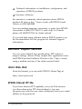
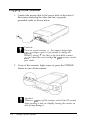
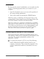
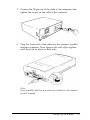
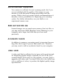
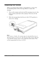
®
™
EPSON Expression
636
COLOR IMAGE SCANNER
All rights reserved. No part of this publication may be reproduced, stored in a retrieval
system, or transmitted in any form or by any means, electronic, mechanical, photocopying,
recording, or otherwise, without the prior written permission of Seiko Epson Corporation.
No patent liability is assumed with respect to the use of the information contained herein.
Neither is any liability assumed for damages resulting from the use of the information
contained herein.
Neither Seiko Epson Corporation nor its affiliates shall be liable to the purchaser of this
product or third parties for damages, losses, costs, or expenses incurred by purchaser or
third parties as a result of: accident, misuse, or abuse of this product or unauthorized
modifications, repairs, or alterations to this product.
Seiko Epson Corporation and its affiliates shall not be liable against any damages or
problems arising from the use of any options or any consumable products other than those
designated as Original EPSON Products or EPSON Approved Products by Seiko Epson
Corporation.
EPSON is a registered trademark of Seiko Epson Corporation, and Expression, ES-1200C,
and Easy Setup are trademarks of Epson America, Inc.
General Notice: Other product names used here in are for identification purposes only and may be
trademarks of their respective owners. EPSON disclaims any and all rights in those marks.
Copyright © 1996 by Epson America, Inc.
Torrance, CA
User’s Guide
FCC Compliance Statement
for United States Users
This equipment has been tested and found to comply with the limits for a Class B digital
device, pursuant to Part 15 of the FCC Rules. These limits are designed to provide
reasonable protection against harmful interference in a residential installation. This
equipment generates, uses, and can radiate radio frequency energy and, if not installed
and used in accordance with the instructions, may cause harmful interference to radio or
television reception. However, there is no guarantee that interference will not occur in a
particular installation. If this equipment does cause interference to radio and television
reception, which can be determined by turning the equipment off and on, the user is
encouraged to try to correct the interference by one or more of the following measures.
0 Reorient or relocate the receiving antenna
0 Increase the separation between the equipment and receiver
0 Connect the equipment into an outlet on a circuit different from that to which the
receiver is connected
0 Consult an experienced radio/TV technician for help.
WARNING
The connection of a non-shielded equipment interface cable to this equipment will
invalidate the FCC Certification of this device and may cause interference levels that
exceed the limits established by the FCC for this equipment. It is the responsibility of the
user to obtain and use a shielded equipment interface cable with this device. If this
equipment has more than one interface connector, do not leave cables connected to unused
interfaces.
Changes or modifications not expressly approved by the manufacturer could void the
user’s authority to operate the equipment.
For Canadian Users
This digital apparatus does not exceed the Class B limits for radio noise emissions from
digital apparatus as set out in the radio interference regulations of the Canadian
Department of Communications.
Le present appareil numerique n’bmet pas de bruits radioblectriques d&passant les limites
applicables aux appareils numeriques de Classe B prescrites dans le Gglement sur le
brouillage radioelectrique edict& par le Minis&e des Communications du Canada.
A Note Concerning Responsible Use of
Copyrighted Materials
Like photocopiers, scanners can be misused by improper scanning of copyrighted
material. Although Section 1070f the U.S. Copyright Act of 1976 (Title 17, United States
Code), the “fair use” doctrine, permits limited copying in certain circumstances, those
circumstances may not be as broad as some people assume. Unless you have the advice of
a knowledgeable attorney, be responsible and respectful by not scanning published
material without the permission of the copyright holder.
ii
Scanner Parts
OPERATE button
transportation lock lever
option interface connector
And terminal
parallel interface connector
Contents
lntroduction
Features . . . . . . . . . . . . . . . .
Options . . . . . . . . . . . . . . . .
About This Guide . . . . . . . . . .
Warnings, Cautions, and Notes . .
Where to Get Help . . . . . . . . .
Electronic Support Services . . . .
World Wide Web . . . . . . . .
EPSON Internet FTP Site . . . .
EPSON Download Service . . .
EPSON Fax-on-Demand Service
EPSON Forum on CompuServe
Important Safety Instructions . . .
Chapter 1
1
2
3
3
3
4
4
4
5
5
5
5
Setting Up the Scanner
Choosing a Place for the Scanner . . . . . . . . . . . . . . . . .
Releasing the Transportation Lock Lever . . . . . . . . . . . .
Plugging in the Scanner . . . . . . . . . . . . . . . . . . . . . .
Initialization . . . . . . . . . . . . . . . . . . . . . . . . . . . . .
Connecting the Scanner to Your Computer . . . . . . . . . . . .
Connecting the Scanner to a Parallel Interface . . . . . . . . . .
SCSI Setup . . . . . . . . . . . . . . . . . . . . . . . . . . . .
Installing Scanner Software . . . . . . . . . . . . . . . . . . . .
1-2
1-3
1-4
1-5
1-5
1-6
1-8
1-12
...
zzz
Chapter 2
Scanner Basics
Lights and Buttons . . . . . . . . . . . . .
Scanner errors . . . . . . . . . . . . . .
Placing a Document on the Scanner . . .
Removing the Document Cover . . . . .
Recommended Equipment . . . . . . . .
RAM and hard disk size . . . . . . . .
Accelerator boards . . . . . . . . . . .
Video cards . . . . . . . . . . . . . . .
Monitors . . . . . . . . . . . . . . . . .
File compression software . . . . . . .
Maintenance . . . . . . . . . . . . . . . . .
Replacing the fluorescent lamp . . . .
Transporting the Scanner . . . . . . . . .
2-2
2-3
2-3
2-6
2-7
2-7
2-7
2-7
2-8
2-8
2-8
2-9
2-10
Chapter 3 Options
Using the Transparency Unit . . . . . . . . . . . . . . . . .
Unpacking the transparency unit . . . . . . . . . . . . .
Removing the shipping screw . . . . . . . . . . . . . .
Installing the transparency unit . . . . . . . . . . . . . .
Storing the transparency guides and reflective
document mat . . . . . . . . . . . . . . . . . . . . . .
Positioning transparencies and slides . . . . . . . . . .
Scanning normal (reflective) documents . . . . . . . .
Using the Automatic Document Feeder . . . . . . . . . . .
Unpacking the automatic document feeder . . . . . . .
Installing the automatic document feeder . . . . . . . .
Loading documents in the automatic document feeder
Paper jams . . . . . . . . . . . . . . . . . . . . . . . . . .
Loading documents manually . . . . . . . . . . . . . .
Document specifications . . . . . . . . . . . . . . . . . .
iv
3-2
3-2
3-3
3-4
3-6
3-7
3-11
3-12
3-13
3-13
3-15
3-17
3-18
3-18
Chapter
Troubleshooting
Indicator Lights . . . .
Command error . .
Interface error . . .
Fatal error . . . . .
Option error . . . .
Problems and Solutions
.
.
.
.
.
.
.
.
.
.
.
.
.
.
.
.
.
.
.
.
.
.
.
.
.
.
.
.
.
.
. . . . . . . . . . . . . . . . . .
. . . . . . . . . . . . . . . . . .
. . . . . . . . . . . . . . . . . .
. . . . . . . . . . . . . . . . . .
. . . . . . . . . . . . . . . . . .
. . . . . . . . . . . . . . . . . .
4-2
4-2
4-3
4-3
4-3
4-4
Appendix
Scanner Specifications . . . . . . . . . . . . . . . . .
Electrical Specifications . . . . . . . . . . . . . . . . .
Environmental Conditions . . . . . . . . . . . . . . .
Safety Approvals . . . . . . . . . . . . . . . . . . . . .
Source Document Specifications . . . . . . . . . . .
Parallel Interface Specifications . . . . . . . . . . . .
SCSI Specifications . . . . . . . . . . . . . . . . . . .
Initialization . . . . . . . . . . . . . . . . . . . . . . .
A-2
A-3
A-4
A-4
A-5
A-5
A-6
A-7
Index
V
The EPSON Expression™ 636 is a true 600-dpi full-color flatbed
image scanner with a letter or A4 size scanning area. It has the
ability to scan in color or grayscale, making it ideal for virtually
all uses, from simple drawings to complex full-color
illustrations. It provides extremely high-quality color scanning
by reading 36 bits per pixel and saving 24 bits per pixel.
Features
The scanner offers the following features:
0
Full-color or grayscale reading. For color reading, you can
select up to 16 million colors. For grayscale, you can select
up to 256 gray shades.
0
Scanning resolution of 600 dpi. The output resolution is
selectable to match the resolution of your output device;
output resolutions of 50 dpi to 4800 dpi (interpolated) are
available.
0
Automatic Area Segmentation (AAS). This feature enables
the scanner to separate text from photographs on a page so
that grayscale images are clearer and text recognition is
more accurate.
0
Text Enhancement Technology. This feature enhances the
recognition accuracy when you use the scanner for optical
character recognition (OCR) scanning.
0
Two resident interfaces, bidirectional parallel and SCSI.
Using these interfaces, you can connect two computers to
the scanner at the same time.
Introduction 1
0
Higher quality output with EPSON TWAIN’s “Best &
de-screening” option. Selecting this option removes moire
(interference) patterns from scanned images.
0
The EPSON Scan! II and EPSON TWAIN scanning utilities.
This software lets you take full advantage of your scanner’s
advanced features. You can scan images and save them to disk
as files, use application programs that support the
industry-standard TWAIN interface, export images in a variety
of file formats, and calibrate your scanner.
0
Software control of all scanner functions. Software
commands are backward compatible with the EPSON
ES-1200CTM color image scanner.
Options
The following optional items are available to expand the
versatility of your scanner. For information on using these
options, see Chapter 3 of this guide and the documentation that
comes with the option.
Transparency Unit
This option allows you to scan transparent materials, primarily
35 mm slides and black-and-white negatives. It has a maximum
reading area of 8.5 x 11.7 inches (216 x 297 mm), which allows
you to scan transparent materials up to letter or A4 size.
Automatic Document Feeder
This option is designed primarily for optical character recognition
(OCR) scanning. The automatic document feeder allows you to
scan up to 30 pages automatically. You can then use them in a
word processing program just as if you had typed them yourself.
2 Introduction
About This Guide
Chapter 1 describes setting up your scanner and connecting
it to your computer. Be sure to read this first. Chapter 2 gives
basic information on using your scanner, including maintenance
and transportation. Chapter 3 describes how to use the optional
transparency unit and automatic document feeder, and Chapter 4
provides troubleshooting information. The Appendix lists the
scanner’s specifications.
Warnings, Cautions, and Notes
Warnings must be followed carefully to avoid bodily injury.
ia
cl
Cautions must be observed to avoid damage to your
equipment.
Notes contain important information and useful tips on the operation
of your scanner.
Where to Get Help
EPSON provides customer support and service through a
network of authorized EPSON Customer Care Centers. Dial
(800) 922-8911 for the nearest location or the following services:
0
Fax-on-Demand access to EPSON’s technical information
library
0
Literature on current and new products
0
The location of your nearest Authorized EPSON Reseller or
Customer Care Center
Introduction 3
0
Technical information on installation, configuration, and
operation of EPSON products
0 Customer relations.
For answers to commonly asked questions about EPSON
products 24 hours a day, 7 days a week, call EPSON Sound
Advice at (800) 442-2110.
You can purchase manuals, accessories, or parts from EPSON
Accessories at (800) 873-7766 (U.S. sales only). In Canada,
please call (800)873-7766 for dealer referral.
If you need help using software with an EPSON product, see
the documentation for that program for technical support
information.
Electronic Support Services
You can access helpful tips, specifications, DIP switch or
jumper settings, drivers, FAQs, sample files, application notes,
and EPSON product bulletins 24 hours a day, 7 days a week,
using a modem and one of the online services below.
World Wide Web
From the Internet, you can reach EPSON’s Home Page at
http://www.epson.com
EPSON Internet FTP Site
If you have Internet FTP capability, use your Web browser
(or other software for FTP downloading) to log onto
ftp.epson.com with the user name anonymous and your e-mail
address as the password.
4 Introduction
EPSON Download Service
You can call the EPSON Download Service BBS at
(800) 442-2007. Set your communications software to 8 data
bits, 1 stop bit, no parity. Modem speed can be up to 28.8 Kbps.
EPSON Fax-on-Demand Service
You can access EPSON’s technical information library by
calling (800) 442-2110 or (800) 922-8911 and selecting the
appropriate phone option. You must provide a return fax
number to use Fax-on-Demand.
EPSON Forum on CompuServe
Members of CompuServe® can type GO EPSON at the menu
prompt to reach CompuServe’s Epson America Forum. As
an owner of an EPSON product, you are eligible for a free
introductory CompuServe membership, which entitles you to
an introductory credit and your own user ID and password.
To take advantage of this offer in the U.S. or Canada, call
(800) 848-8199 and ask for representative #529.
Important Safety Instructions
Read all of these instructions and save them for later reference.
Follow all warnings and instructions marked on the scanner.
0
Unplug the scanner before cleaning. Clean with a damp
cloth only. Do not spill liquid on the scanner.
0
Do not place the scanner on an unstable surface or near a
radiator or heat source.
0
Do not block or cover the openings in the scanner’s cabinet.
Do not insert objects through the slots.
Introduction 5
0
Use only the type of power source indicated on the
scanner’s label.
0
Connect all equipment to properly grounded power
outlets. Avoid using outlets on the same circuit as
photocopiers or air control systems that regularly switch on
and off.
0
Place the scanner near a wall outlet where the plug can be
easily unplugged.
Placez le scannezu pres d’une de contacte 024 la fiche peut2tre debranchke facilement.
0
Do not let the power cord become damaged or frayed.
0
If you use an extension cord with the scanner, make sure
the total ampere rating of the devices plugged into the
extension cord does not exceed the cords ampere rating.
Also, make sure the total of all devices plugged into the
wall outlet does not exceed 15 amperes.
0
Except as specifically explained in this user’s guide, do not
attempt to service the scanner yourself.
0
Unplug the scanner and refer servicing to qualified service
personnel under the following conditions:
If the power cord or plug is damaged; if liquid has entered
the scanner; if the scanner has been dropped or the cabinet
damaged; if the scanner does not operate normally or
exhibits a distinct change in performance. Adjust only those
controls that are covered by the operating instructions.
0
If you plan to use the scanner in Germany, observe the
following:
To provide adequate short-circuit protection and overcurrent protection for this scanner, the building installation
must be protected by a 16 Amp circuit breaker.
Bei Anschluj3 des Scanners an die Stromversorgung muj3
sichergestellt werden, daj3 die Gebiiudeinstallation mit einem 16
A-Z&erstromschalter abgesichert ist.
6 Introduction
Chapter 1
Setting Up the Scanner
Choosing a Place for the Scanner . . . . . . . . . . . . . . . . .
Releasing the Transportation Lock Lever
Plugging in the Scanner
1-2
. . . . . . . . . . . . 1-3
. . . . . . . . . . . . . . . . . . . . . .
1-4
. . . . . . . . . . . . . . . . . . . . . . . . . . . . .
1-5
. . . . . . . . . . .
1-5
Connecting the Scanner to a Parallel Interface . . . . . . . . . .
SCSI Setup . . . . . . . . . . . . . . . . . . . . . . . . . . . .
1-6
1-8
Initialization
Connecting the Scanner to Your Computer
Installing Scanner Software
. . . . . . . . . . . . . . . . . . . .
Setting Up the Scanner
1-12
1-1
I
Choosing a Place for the Scanner
Follow these guidelines when you select a location for the
scanner:
0
Place the scanner on a flat, stable surface. The scanner does
not operate properly if it is tilted or at an angle.
0
Place the scanner close enough to the computer for the
interface cable to reach it easily.
0
Allow some space behind the scanner for the cables, and
make sure to place the scanner where you can easily
unplug the power cord. Also allow sufficient space above
the scanner so that you can fully raise the document cover.
mm) or more
21.7 inches (550 mm)
5.2 inches (133 mm)
5.9 inches (150 mm) or more
_J
1 3 . 1 i n c h e s
( 3 3 2
m m )
22.2 inches (563 knm)
1-2
0
Keep the scanner away from high temperatures and
humidity and places subject to rapid changes in
temperature or humidity.
0
Keep the scanner away from direct sunlight and strong
light sources.
0
Avoid places subject to shocks or vibrations.
Setting Up the Scanner
Releasing the Transportation Lock Lever
Before you connect the scanner to a power source, follow the
steps below to release the transportation lock lever.
1.
Place the scanner on a flat, stable surface with its rear panel
facing you.
2.
Slide the transportation lock lever to the UNLOCK position
as shown below.
Note:
Be sure to return the transportation lock lever to the LOCK position
before ~024 store OY transport the scanner.
Setting Up the Scanner
1-3
Plugging in the Scanner
1.
Connect the power cable to the power inlet on the back of
the scanner and plug the other end into a properly
grounded outlet as shown below.
e
2.
If any of the scanner’s lights come on, press the OPERATE
button to turn off the scanner.
e
1-4
Caution:
There are several versions of this scanner designed for
dzjJimxt voltages, and it is not possible to change the
scanner’s voltage. If the label on the back of the scanner
does not show the correct voltage for your country, contact
your dealer.
Caution:
Whenever ~024 turn off the scanner, wait at least 10 seconds
before turning it back on. Rapidly turning the scanner on
and off may damage it.
Setting Up the Scanner
Initialization
By observing the scanner’s initialization, you can make sure the
scanner is operating properly before you connect it to your
computer.
1.
Open the document cover so you can see the operation of
the scanner during initialization.
2.
Turn on the scanner by pressing the OPERATE button.
While the scanner is initializing, the fluorescent lamp on the
carriage flashes. If the carriage is not at the home position (the
rear of the scanner), it moves to the home position.
When the scanner has completed its initialization, the READY
light comes on. If the scanner does not work as described, turn
it off. Make sure that the power cord is firmly plugged in and
that the transportation lock lever is in the UNLOCK position.
Then turn on the scanner and check its operation again.
Connecting the Scanner to Your Computer
Your scanner has both a bidirectional parallel interface and a
SCSI interface. Cables can be connected to both interfaces at the
same time. The scanner automatically switches to the
appropriate interface.
0
To connect the scanner to a PC, do one of the following:
Install a bidirectional parallel interface board in your
computer, if necessary. Then connect the computer to the
scanner’s bidirectional interface as described in the next
section.
Setting Up the Scanner
1-5
Note:
IBM® PS/2® computers and some other PCs have built-in
bidirectional parallel interfaces. You need to install an additional
one in these computers only if you use the built-in parallel
interface for your printer.
Install a SCSI board in your computer, if necessary. Then
connect the computer to the scanner’s SCSI connector as
described under “SCSI Setup” on page 1-8.
0
To connect the scanner to an Apple® Macintosh® computer,
you do not need to install a SCSI board in your computer;
simply connect your scanner to your Macintosh’s built-in
SCSI port as described under “SCSI Setup” on page 1-8.
To use an interface correctly, you may need to change settings
on the scanner, computer, or both. The following sections
explain how to set up and connect each type of interface.
Connecting the Scanner to a Parallel Interface
To connect the scanner to a parallel interface on your computer,
use a standard shielded parallel interface cable and follow the
steps below.
Caution:
The scanner’s bidirectional parallel interface requires a
bidirectional interface on your computer. Check your
computer’s specifications to see if its built-in parallel interface
is bidirectional.
1.
1-6
Make sure that both the scanner and computer are turned
off.
Setting Up the Scanner
2.
Connect the 25-pin end of the cable to the computer; then
tighten the screws on the sides of the connector.
3.
Plug the 36-pin end of the cable into the scanner’s parallel
interface connector. Then squeeze the wire clips together
until they lock in place on both sides.
Note:
If your parallel cable has a ground wire, attack it to the scanner’s
ground terminal.
Setting Up the Scanner
1-7
SCSI Setup
For some PCs, you must first install a SCSI board in your
computer. All Macintosh computers have built-in SCSI ports;
you do not need to install a SCSI board. Follow the directions
below to connect the scanner to your PC or Macintosh.
SCSI connections
The SCSI interface allows you to connect up to eight devices,
including the computer, in a “daisy chain” arrangement. Only
the first SCSI device in a daisy chain is connected to the
computer; each of the other devices is connected to the
previous device.
Each device has a SCSI ID number: the computer is usually
number 7, and each of the other devices must have a different
number between 0 and 6. Also, the first device and the last
device in the chain (not including the computer) must have
terminators. If any other devices in the chain have terminators,
the terminators must be turned off. The scanner has two 50-pin
SCSI connectors and a built-in terminator that you can turn on
or off.
Setting the SCSI ID number
The factory-set SCSI ID number of the scanner is 2. The
computer’s SCSI ID number is usually 7. If one of the SCSI
devices in your system already has the SCSI ID number 2,
change the scanner’s SCSI ID number to an unused number as
described on the next page.
1-8
Setting Up the Scanner
1.
Locate the SCSI ID rotary switch on the rear panel of the
scanner.
2.
To change the scanner’s SCSI ID, turn the dial to the desired
number.
Caution:
Do not set the scanner’s SCSI ID to a number that is
already assigned to another device; the computer, scanner,
and other devices will not function properly.
Note:
If your software supports only the ES-1200C scanner, set the dial
to the position marked * to select ES-1200C Emulation mode. In
ES-1200C Emulation mode, the scanner’s SCSI ID number is 2.
If one of your other SCSI devices already has the SCSI ID
number 2, change that device’s number to an unused number.
Setting Up the Scanner
1-9
Using the termination switch
The scanner has a built-in SCSI terminator. If the scanner is the
only SCSI device you connect to your computer or if it is the
last device in the daisy chain, leave the termination switch
turned on.
If the scanner is in the middle of a daisy chain, turn off the
termination switch.
Connecting the scanner to your computer or to another
SCSI device
To connect the scanner to a Macintosh, use a SCSI cable with a
25-pin connector on one end (for the computer) and a 50-pin
connector on the other end (for the scanner). To connect the
scanner to a PC or another SCSI device, use a SCSI cable with
50-pin connectors on both ends. Connect the scanner as
follows:
1.
1-10
Make sure that the scanner, the computer, and all other SCSI
devices are turned off and unplugged from the power
source.
Setting Up the Scanner
2.
Connect the 50-pin end of the cable to either the top or
bottom SCSI connector of the scanner; then squeeze the
wire clips together until they lock in place on both sides.
3.
Connect the other end of the cable to the SCSI port of your
computer or other SCSI device.
Note:
The SCSI port of the Macintosh is the larger port with the
SCSI icon @ over it.
4.
Plug in the power cables of your computer, scanner, and
other external SCSI devices.
5.
Turn on the scanner and any other external SCSI devices
before you turn on your computer.
Turning on your computer and external SCSI devices
Always follow the power-on sequence described here when
you turn on your computer and external SCSI devices.
If you have an internal hard disk, turn on the scanner and any
other external SCSI devices you plan to use. Wait a few
seconds; then turn on the computer.
Setting Up the Scanner
1-11
If you have an external hard disk, turn on the scanner, the
external hard disk (which should be first in the daisy chain),
and any other external SCSI devices you plan to use. Wait a few
seconds; then turn on the computer.
SCSI devices in the middle of the daisy chain may be left off if
you don’t plan to use them.
Installing Scanner Software
Now that you have connected the scanner to your computer,
the next thing to do is install your scanner software. Follow the
instructions in your EPSON Scanning Utilities User’s Guide. Then
read Chapter 2, “Scanner Basics,” before you start scanning.
1-12
Setting Up the Scanner
Chapter 2
Scanner Basics
Lights and Buttons . . . . . . . . . . . .
Scanner errors . . . . . . . . . . . .
2-2
2-3
Placing a Document on the Scanner . .
2-3
Removing the Document Cover . . . .
2-6
Recommended Equipment . . . . . . .
RAM and hard disk size . . . . . .
Accelerator boards . . . . . . . . . .
Video cards . . . . . . . . . . . . . .
Monitors . . . . . . . . . . . . . . .
File compression software . . . . .
2-7
2-7
2-7
2-7
2-8
2-8
Maintenance . . . . . . . . . . . . . . .
Replacing the fluorescent lamp . .
2-8
2-9
Transporting the Scanner . . . . . . . . . . . . . . . . . . . . . .
2-10
Scanner Basics 2-1
Lights and Buttons
The scanner has three indicator lights and two buttons.
button
button
OPERATE light (green)
Comes on when the scanner is turned on.
READY light (green)
Comes on when the scanner is ready to scan images. This light
flashes during scanning. When an error occurs, this light and
the ERROR light indicate the type of error. See the next page.
ERROR light (red)
Comes on when an error occurs. Along with the READY light, it
indicates the type of error.
OPERATE button
Turns the scanner on and off.
RESET button
Resets the scanner after an error occurs. Pressing this button
during scanning stops the scanner and may cause an error in
the scanning software.
2-2
Scanner Basics
Scanner errors
If an error occurs, the scanner stops operating and the
READY and ERROR lights show the type of error. See Chapter
4, “Troubleshooting.”
Placing a Document on the Scanner
Before scanning a document:
Remember to respect the rights of copyright owners. Do not scan
published text or images without first checking the copyright status.
1.
Turn on the scanner by pressing the OPERATE button.
The OPERATE light comes on.
Scanner Basics 2-3
2-4
2.
Turn on the computer and make sure that the scanner’s
READY light is on. Open the document cover.
3.
Place the document on the document table, with the side to
be scanned down. Make sure that the document is carefully
aligned.
Scanner Basics
4.
Close the document cover gently so that the document does
not move.
Note:
5.
0
Make sure that the document is flat against the glass surface
so that the image is properly focused. Also make sure to close
the document cover. This prevents interference from external
light.
0
Always keep the document table clean. See “Maintenance”
later in this chapter for information on cleaning the scanner.
0
Avoid twisting the document cover when you open or close it.
0
Do not leave photographs on the document table for an
extended period of time; they may stick to the glass.
0
Do not place heavy objects on top of the scanner.
Use your scanner software to scan the image.
Scanner Basics 2-5
Removing the Document Cover
For thick documents or other materials that are hard to scan,
you can remove the document cover. To do this, hold the back
of the document cover behind the hinge and lift straight up.
Do not force the cover off the scanner or lift from in front of the
hinge. This may damage the cover.
Note:
When scanning with the cover removed, make sure you cover any
exposed areas of the document table to prevent interference from
external light.
Reattach the document cover by pushing straight down on the
back of it until it clicks into place.
2-6
Scanner Basics
Recommended Equipment
Your scanner is sufficient for most scanning needs, but if you
are not satisified with the quality of the images on your
monitor or with the speed of image processing, read this
section. While it does not contain specific recommendations, it
describes various possibilities for improving your scanning
system. For further information, see your dealer or an
experienced scanner user.
RAM and hard disk size
Scanned images can use much more memory than text files, so
you may need more RAM (Random Access Memory) in your
computer and a larger hard disk than you have used
previously.
Accelerator boards
In addition to memory, processing speed is important because
large files take longer to process than small ones. Therefore,
you may want to add an accelerator board to your computer.
video cards
A video card that is sufficient for text may not be good enough
for displaying graphic images, especially in color. If all your
scanned images look coarse on your monitor, you may want to
upgrade your video card. You need 24-bit color, also called true
color or millions of colors, to produce the highest quality image
reproductions.
Scanner Basics 2-7
The resolution of your monitor, of course, also affects the
quality of the image you see. Consider a high resolution
monitor if you do precise color work, but first be sure you have
the right video card.
File compression software
Many different programs are available to make image files
smaller for storage or transmission. For example, they can
enable you to store a 3MB image file on a 1.44MB floppy disk.
Some compression software can compress images and restore
them with no loss of data or quality; others compress images
more, but the restored file is not exactly the same as the
original. The difference between the original and restored files
is, however, almost unnoticeable.
Maintenance
To keep your scanner operating at its best, you should clean it
periodically. Before cleaning, unplug the power cable and all
the interface cables connected to the scanner.
Clean the outer case with mild detergent diluted in water.
If the glass of the document table gets dirty, clean it with a soft
dry cloth. If the glass is stained with grease or other hard-toremove material, use a small amount of glass cleaner on a soft
cloth to remove it. Wipe off any remaining liquid with a soft
dry cloth.
Be sure that there is no dust on the glass of the document table.
Dust can cause white spots in your scanned image.
2-8
Scanner Basics
Be careful not to scratch OY damage the glass of the
d0c2md table, and a0 not use a hard OY abrasive brush
to clean it. A damaged glass surface can decrease the
scanning quality.
0 Never use alcohol, thinner, OY corrosive solvent to clean
the scanner. These chemicals can damage the scanner
components as well as the case.
0 Be careful not to spill liquid into the scanner mechanism
OY electronic components. This could permanently damage
the mechanism and circuitry.
0 Do not spray lubricants inside the scanner.
0 Never open the scanner case.
Replacing the fluorescent lamp
The luminosity of the fluorescent lamp declines over time. If
the lamp breaks or becomes too dim to operate normally, the
scanner stops working and both the READY and ERROR lights
flash. When this happens, contact your dealer about replacing
the lamp assembly.
Warning:
Never open the case of the scanner. If you think repairs OY
adjustments are necessary, consult your dealer.
Scanner Basics 2-9
Transporting the Scanner
When you transport the scanner a long distance or store it for
an extended period, follow the steps below to secure the
carriage.
1.
Turn on the scanner and wait until the carriage moves to the
home position (the back of the scanner). Then turn off the
scanner.
2.
Slide the transportation lock lever to the LOCK position to
secure the carriage.
Note:
If the scanner is broken, the carriage may not automatically return to
the home position. If it does not, raise the front of the scanner and hold
it up until the carriage comes to rest at the back of the scanner. Then
set the transportation lock lever to LOCK.
2-10
Scanner Basics
Chapter 3
Options
Using the Transparency Unit . . . . . . . . . . . .
Unpacking the transparency unit . . . . . . . .
Removing the shipping screw . . . . . . . . . .
Installing the transparency unit . . . . . . . . .
Storing the transparency guides and reflective
document mat . . . . . . . . . . . . . . . . . .
Positioning transparencies and slides . . . . .
Scanning normal (reflective) documents . . . .
3-2
3-2
3-3
3-4
Using the Automatic Document Feeder . . . . . . . . . . . . .
Unpacking the automatic document feeder . . . . . . . . .
Installing the automatic document feeder . . . . . . . . . .
Loading documents in the automatic document feeder . .
Paper jams . . . . . . . . . . . . . . . . . . . . . . . . . . . .
Loading documents manually . . . . . . . . . . . . . . . . .
Document specifications . . . . . . . . . . . . . . . . . . . .
3-12
3-13
3-13
3-15
3-17
3-18
3-18
3-6
3-7
3-11
Options 3-1
Using the Transparency Unit
When installed on your scanner, the transparency unit
provides high-quality, full-color scanning of transparencies and
slides. Also, once you install the transparency unit, you can
leave it in place when scanning normal reflective (paper)
documents.
Unpacking the transparency unit
When you unpack your transparency unit, make sure you have
all the items shown below and that none has been damaged
during shipping. Contact your EPSON dealer if any item is
missing or damaged.
reflective
document mat
transparency
guides
3-2 Options
two screws
Removing the shipping screw
To prevent damage during shipping, a shipping screw is
attached to the transparency unit. Follow the steps below to
remove this screw before you install the transparency unit.
1.
Turn the transparency unit so the glass side faces up.
2.
Remove the screw as shown below.
(labeled CLAMP
3.
Insert the screw you just removed into the storage hole as
shown.
labeled STOCK)
Options 3-3
Note:
Before transporting the scanner, you need to remove the transparency
unit and reattach its shipping screw. You can attach the shipping
screw only when the transparency unit’s lamp assembly is in its home
position. To move it to its home position when the transparency unit
is attached to the scanner, close the transparency unit, turn on the
scanner, and then turn it off.
Installing the transparency unit
Follow the steps below to install the transparency unit on the
scanner.
Note:
You cannot have the automatic document feeder and the transparency
unit installed on the scanner at the same time.
1.
Make sure the scanner is turned off, and unplug the
scanner’s power cable.
2.
Remove the scanner’s document cover by holding the cover
behind the hinge and lifting the back of the cover straight
up as shown on page 2-6.
3-4 Options
3.
Locate the two screws at the back of the scanner and slide
the slots on the transparency unit forward underneath
these two screws.
4.
Insert the two screws provided with the transparency unit
into the holes in the scanner as shown below, and then
tighten the screws with a coin.
5. Close the transparency unit.
OPt ions 3-5
6.
Connect the transparency unit’s cable to the option
connector on the scanner. Then reconnect the scanner’s
power cable.
Storing the transparency guides and reflective
document mat
As shown on the next page, the transparency unit comes with
three transparency guides for scanning transparencies or slides
and a reflective document mat for scanning normal paper
documents. To use the transparency guides, see “Positioning
transparencies and slides” on the next page. To use the
reflective document mat, see “Scanning normal (reflective)
documents” on page 3-11.
When you are not using the reflective document mat or the
large transparency guides, you can open the storage slot cover
and insert them into the storage slot for safekeeping. Do not
insert the small transparency guide; you may have trouble
removing it.
3-6 Options
-ransparency guides
I-L
Positioning transparencies and slides
You can scan transparencies or slides of various sizes using the
transparency guides. Select the transparency guide to use
according to the size of your transparency or slide as described
in the table below.
1 Transparency or slide size
1 Appropriate transparency guide
1 Up to 2.4 x 3.5 inches (6 x 9 cm)
1 Small transparency guide
Up to 4 x 5 inches (10.2 x 12.7 cm)
Transparency guide with two
4 x5-inch openings
Up to 4 x 10.25 inches
(10.2 x 26.0 cm)
Transparency guide with two
10.25.inch-long openings
Note:
Before scanning transparencies OY slides, wipe the glass of the
transparency unit, the scanner’s document table, and the narrow
window behind the scanner’s document table with a soft cloth.
Options 3-7
If your transparency is larger than the sizes in the table above,
you can place it directly on the scanner’s document table
without using a transparency guide, as shown below. The
transparency unit allows you to scan transparencies up to
8% x 11 inches (21.6 x 27.9 cm) in size. See your Scanning
Utilities manual for information on scanning with the
transparency unit.
Follow the steps below to position transparencies or slides
using the small transparency guide or the transparency guide
with two 4 x 5-inch openings:
1.
Open the transparency unit.
3-8 Options
2.
Hold up the clear plastic flap and insert the transparency or
slide in the transparency guide, as shown below.
3.
Place the transparency guide containing the transparency or
slide face down on the scanner’s document table, aligning it
in the upper right corner as shown below.
4.
If the reflective document mat is in place, remove it from the
transparency unit.
5.
Close the transparency unit. (If you do not close it
completely, an option error results and you cannot scan the
document.)
Options 3-9
Follow the steps below to position transparencies or slides
using the transparency guide with two 10.25-inch-long
openings:
Open the transparency unit.
Place the transparency guide on the scanner’s document
table.
Place the transparency face down on the document table,
aligning it with the upper right corner of the transparency
guide as shown below.
4.
If the reflective document mat is in place, remove it from the
transparency unit.
5.
Close the transparency unit. (If you do not close it
completely, an option error results and you cannot scan the
document.)
3-10 Options
Scanning normal (reflective) documents
To scan a normal reflective (paper) document when the
transparency unit is installed, always use the reflective
document mat included with the transparency unit. Also, make
sure you remove the transparency guide from the scanner’s
document table.
Insert the reflective document mat as described below.
1.
Open the transparency unit.
2.
Insert the tabs on the reflective document mat into the slots
on the transparency unit and slide the mat into place.
Options 3-11
3.
Position the reflective document and close the transparency
unit.
To remove the reflective document mat, slide it up and out of
the slots on the transparency unit.
Using the Automatic Document Feeder
The automatic document feeder allows you to automatically
load multiple-page documents into the scanner. It is
particularly useful for OCR (optical character recognition)
scanning, or for creating an image database.
3-12 Options
Unpacking the automatic document feeder
When you unpack your automatic document feeder, make sure
you have all the items shown below and that none is damaged.
If any item is missing or damaged, contact your EPSON dealer.
two screws
automatic document feeder
Installing the automatic document feeder
Follow the steps below to install the automatic document
feeder on your scanner.
Note:
You cannot have the transparency unit and the automatic document
feeder installed on the scanner at the same time.
1.
Make sure the scanner is turned off, and unplug the
scanner’s power cable.
2.
Remove the scanner’s document cover by holding the cover
behind the hinge and lifting the back of the cover straight
up as shown on page 2-6.
Options 3-13
3.
Locate the two screws at the back of the scanner and slide
the slots on the automatic document feeder forward
underneath these two screws. (Do not remove the
protective materials from the automatic document feeder’s
mounting hardware yet.)
4.
Insert the two screws provided with the automatic
document feeder into the holes in the scanner as shown
below, and then tighten the screws with a coin.
3-14 Options
5.
Remove the protective materials from the automatic
document feeder’s mounting hardware.
6.
Close the automatic document feeder.
7.
Connect the automatic document feeder’s cable to the
option connector on the scanner. Then reconnect the
scanner’s power cable.
Loading documents in the automatic document feeder
You can load up to 30 sheets in the automatic document feeder,
based on a paper weight of 17 lb and a stack thickness of
0.24 inches (6.0 mm) or less. You can load documents of the
following sizes:
Checks
3 x 5 inches (76 x 127 mm)
B5
7.17x 10.1 inches(l82x257mm)
A4
8.27 x 11.7 inches (210 x 297 mm)
Letter
8.5 x 11 inches (215.9 x 279.4 mm)
Note:
See “Document specifications” at the end of this chapter for more
information on the d0c2mkws you can load in the automatic
document feeder.
Options 3-15
Follow the steps below to load documents into the automatic
document feeder.
1.
Slide the left edge guide all the way to the left and place
your documents in the feeder tray with the side you want
to scan facing up. Then move the right edge guide so it is
flush with the right edge of the document stack.
Note:
For checks, move the left edge guide to the center until it stops.
Then place your checks in the tray with the side you want to scan
facing up, and move the right edge guide until it is flush with the
right edge of the check stack.
3-16 Options
2.
Insert the document stack into the automatic document
feeder until it meets resistance.
Documents are fed into the lower tray when scanning is finished.
Paper jams
If a paper jam occurs, first open the automatic document
feeder’s cover. Then pull forward on the jam-release lever and
slowly pull the jammed paper out of the feeder mechanism. (Be
careful not to pull too hard; the paper may tear, making it more
difficult to remove.)
After you remove the jammed paper, close the automatic
document feeder cover and reset the scanner.
Options 3-17
Loading documents manually
You can load documents manually even when the automatic
document feeder is installed.
To load a document manually, lift the automatic document
feeder and place the document on the scanning surface. Then
lower the automatic document feeder and scan the document.
Note:
Always close the automatic document feeder and its cover before
scanning. Opening the automatic document feeder or its cover while
it is operating causes an option error, and paper feeding stops.
Document specifications
Make sure the documents you load in the automatic document
feeder meet the requirements below.
Size:
Width
Length
3 to 8.5 inches (76 to 215.9 mm)
5 to 11.7 inches (127 to 297 mm)
Thickness:
0.0028 to 0.0063 inches
(0.07 to 0.16 mm)
Weight:
12 to 29 lb (45 to 110 g/m’)
Paper quality:
High-quality bond or thermal paper
Document type:
Documents printed with impact
printers, laser printers, ink jet printers,
photocopiers, or facsimile machines
3-18 Options
Document condition
Check that your document is clean and in good condition
before you load it in the automatic document feeder. Make sure
of the following:
0
The ink on the document is dry.
0
The document has no holes or cut-out areas in it, and is not
ripped or wrinkled.
0
The document has no staples, paper clips, or other
materials attached to it. These may damage the feeder
mechanism.
0
The document has no folds closer than 0.31 inches (8 mm)
from its edges.
0
The document is not a multipart form and is not bound,
such as in a book or magazine.
0
The document has no rear carbon coating.
Other precautions
Do not feed photographs or valuable original artwork into the
automatic document feeder; if a document is misfed, it may
become wrinkled or damaged.
When you scan high-quality color or halftone documents, it is
best to open the automatic document feeder and scan each
document individually.
Options 3-19
Chapter 4
Troubleshooting
Indicator Lights . .
Command error
Interface error .
Fatal error . . .
Option error . .
.
.
.
.
.
.
.
.
.
.
.
.
.
.
.
.
.
.
.
.
.
.
.
.
.
.
.
.
.
.
.
.
.
.
.
4-2
4-2
4-3
4-3
4-3
Problems and Solutions . . . . .
4-4
Troubleshooting 4-1
If you encounter any problems while using the scanner, check
this chapter for possible solutions. Most problems fall into the
following major categories:
0
Incorrect setup of the interface
0
Inappropriate selection of scanner functions
0
Incorrect setup of your computer or software
0
Incorrect operation of your software.
Also see the documentation that came with your software,
computer, and printer for possible solutions.
Indicator Lights
If an error occurs, the scanner stops operating and the READY
and ERROR lights show the type of error.
READY light
On
1 Off
ERROR light
Error type
On
Command error
1 Flashing
Interface error
Flashing
Flashing
Fatal error
Off
Off
Option error
Command error
The scanner has received incorrect commands from your
scanning software.
If this error occurs, try to rescan the document. The scanner
returns to normal when it receives correct commands.
Normally you do not need to reset the scanner.
4-2
Troubleshooting
I
Interface error
The interface setup is wrong, or the scanner is not properly
connected to the computer.
If this error occurs, check the interface connection. See
“Connecting the Scanner to Your Computer” in Chapter 1.
Then press the RESET button or turn the scanner off and back
on to reset it.
Fatal error
This indicates one of the following problems:
0
The transportation lock lever is set to the LOCK position.
0
The fluorescent lamp needs to be replaced.
0
The scanner is broken.
0
There is a problem, such as an open cover, with the
optional transparency unit or the optional automatic
document feeder.
Check that the transportation lock lever is set to the UNLOCK
position and check any installed options; then press the RESET
button. If the scanner still does not operate properly, try
turning the scanner off and then back on. If it still does not
operate properly, or if this error occurs repeatedly, consult
your dealer.
Option error
This indicates a problem such as a paper jam with an installed
option unit.
Check the option unit and correct the problem. See Chapter 3,
“Options.”
Troubleshooting 4-3
Problems and Solutions
The OPERATE light does not come on.
Make sure the power cable is correctly plugged into the
scanner and the power outlet.
The READY light does not come on.
Make sure the scanner is correctly connected to the computer
and that the computer is turned on.
The scanner does not start scanning.
Make sure that you have selected the correct interface port and
settings with your software. Also make sure the interface board
in your computer is properly installed.
If you are using the SCSI interface, confirm that the termination
and SCSI ID rotary switch are set correctly. See “SCSI Setup”
on page 1-8.
If you have other expansion boards in your computer, make
sure that they are not interfering with the interrupt setting of
the interface board for your scanner. (See your computer
manual.)
The scanner software does not work properly.
Be sure you have correctly installed and set up your scanner
and application software. Also make sure your software
supports this scanner model. (See your Easy Setup and software
manuals.)
4-4
Troubleshooting
Make sure that your computer system meets the requirements,
such as the operating system version, specified for your
software.
Confirm that the computer has enough memory for your
software. If you are running other software at the same time,
using RAM resident programs, or have many device drivers,
the computer may not have enough memory left. (See your
Easy Setup, application software, and computer manuals.)
The entire image is distorted or blurred.
Make sure that the document is placed flat against the
document table.
You may have accidentally moved the document during
scanning. Check the position of the document and do not move
it while the scanner is operating.
See that the scanner is not tilted or placed on an unstable
surface.
Part of the image is distorted or blurred.
Part of the document may be wrinkled, warped, or not in
contact with the document table. Be sure the document is
uniformly flat.
Caution:
Do not place heavy objects on the document table.
The edges of the document are not scanned.
The document table has non-readable areas around the edges.
If part of your document extends beyond the maximum limits
marked on the document table edge guides, you may have to
reposition your document so that the image you want to scan is
within the readable area.
Troubleshooting 4-5
Color is patchy or distorted at the edges of the image.
If the document is very thick or warped at the edges, the edges
of the image may be discolored. Cover the edges of the
document with opaque paper to block outside light.
If part of the document extends beyond the document table,
that edge may not be in contact with the document table.
Change the position of the document.
The image is faint or out of focus.
Check that the document is placed flat against the document
table.
Darken your image with the brightness setting in your software.
The image is too dark.
Adjust the brightness with your software. Also check the
brightness and contrast of your display screen.
Straight lines are jagged in the image.
The document may be placed at an angle on the document
table. Position it so that the horizontal and vertical lines are
carefully aligned with the scales on the top and side of the
document table.
The image does not look the same as the original.
Try different combinations of image settings using your
scanner software.
4-6
Troubleshooting
Your software may not have sufficient color matching and
color management features, or these components of your
software may not be correctly installed. (See your application
software and computer manuals.)
If you are importing an image file into your application
software, make sure the file format is one your software can
read. Also check that the image settings in your application are
appropriate for the type of image you want to scan. (See your
application software and Scanning Utilities manuals.)
A line of dots is always missing in the scanned image.
If this happens in your printed image only, your printer or its
print head is probably malfunctioning. (See your printer
manual.)
If this happens on both your screen and printout, the scanner’s
sensor may be malfunctioning. Consult your dealer.
When halftoning is used, textured patterns of dots appear on
particular areas of an image.
This is normal. See your application software manuals for more
information on halftoning and moire (interference) patterns.
Colors on your monitor differ from those in the original document.
Check the image settings in your scanner software, especially
data format (bits/pixel/color), gamma correction, and color
correction. Try a different combination of these settings.
Check the color matching and color management capabilities of
your computer, display adapter, and software. Some
computers can change the color palette to adjust colors on your
screen. (See your application software and computer manuals.)
Troubleshooting 4-7
Exact matching of colors is very difficult. Check your Scanning
Utilities, application software, computer, and monitor manuals for
information on color matching and calibration.
Printed colors differ from those in the original document.
Exact reproduction of colors is very difficult. See your
application software manual for guidance on color matching.
The printed image is larger or smaller than the original image.
The image size settings in your software determine the size of
the printed image. Do not use the size of the image on your
monitor to judge the printed size.
The printer does not print the image, the printout is garbled, or the
printout is not an image.
Check that the printer is properly connected to the computer
and is correctly set up. (See your printer manual.)
Check that your software is properly installed and set up for
your printer. (See your application software and printer
manuals.)
4-8
Troubleshooting
Appendix
. . . . . . . . . . . . . . . . . . . . . . .
A-2
Electrical Specifications . . . . . . . . . . . . . . . . . . . . . . .
A-3
Environmental Conditions . . . . . . . . . . . . . . . . . . . . .
A-4
Safety Approvals . . . . . . . . . . . . . . . . . . . . . . . . . . .
A-4
. . . . . . . . . . . . . . . . .
A-5
Parallel Interface Specifications . . . . . . . . . . . . . . . . . .
A-5
Scanner Specifications
Source Document Specifications
. . . . . . . . . . . . . . . . . . . . . . . . .
A-6
. . . . . . . . . . . . . . . . . . . . . . . . . . . . .
A-7
SCSI Specifications
Initialization
Appendix A-l
Scanner Specifications
Scanner type:
Flatbed, color
Photoelectric device:
Color CCD (Charged Coupled Device)
line sensor
Effective pixels:
5096 dots by 7020 dots at 600 dpi, 100%
Document size:
8.5 x 11.7 inches (216 x 297 mm)
letter or A4 size
(The reading area can be specified from
software.)
Scanning resolution:
600 dpi (main, sub)
Output resolution:
50 dpi to 4800 dpi in 1 dpi steps
Values above 600 through software
interpolation
Color separation:
RGB color filters on CCD
Reading sequence:
Monochrome
One-pass scanning
Color page sequence
Three-pass scanning (R, G, B)
Color byte sequence
One-pass scanning (R, G, B)
Color line sequence
One-pass scanning (R, G, B)
Zoom:
50% to 200% in 1% steps
Image data:
12 bits per pixel per color saved as 8 bits per
pixel per color maximum
Brightness:
7 levels
Line art settings:
Fixed threshold
Text Enhancement Technology
(enable/disable selectable)
Halftoning process:
Enable/disable selectable
3 halftoning modes (A, B, and C) and
4 dither patterns (A, B, C, and D) for
bi-level and quad-level data
Halftoning mode A only in color line
sequence mode; 2 downloadable dither
patterns
A-2 Appendix
Gamma correction:
2 types for CRT display
3 types for printer
1 type for user-defined
Color correction:
1 type for CRT display
3 types for printer output (available in
color line sequence mode only)
1 type for user-defined
Interface:
Bidirectional parallel and SCSI
Light source:
Xe-gas cold cathode fluorescent lamp
Reliability:
100,000 cycles of carriage movements
(main unit MCBF)
Dimensions:
Width: 13 inches (332 mm)
Depth: 22.2 inches (563 mm)
Height: 5.2 inches (133 mm)
Weight:
Approx. 22 lb (10 kg)
I Input voltage range
I
120 V model
I
103.5 to 132VAC
1
220-240 V model
1
198 to 264 VAC
Rated frequency
50 to 60 Hz
Input frequencv
49.5 to 60.5 Hz
Rated current
I Power consumption
I
0.8 A
I
0.4 A
I Approx. 25 W, 50 W maximum with optional unit
Note:
Check the label on the back of the scanner for the voltage of your scanner.
Appendix A-3
I
I
I
I
Environmental Conditions
Temperature:
Operation
41” to 95” F (5’ to 35” C)
Storage
-13” to 140” F (-25” to 60” C)
Humidity:
Operation
10% to 80%, without condensation
Storage
10% to 85%, without condensation
Operating conditions:
Ordinary office or home conditions.
Extremely dusty conditions should be
avoided. Operation under direct sunlight
or near a strong light source should be
avoided.
Note:
Specifications are subject to change without notice.
Safety Approvals
Safety standards:
120 V model
UL 1950 with D3, CSA C22.2 950 with D3
220-240 V model
EN 60950 (TiiV)
EN 60950 Nordic Deviation (NEMKO)
EMC:
120 V model
FCC part 15 subpart B class B
CSA C108.8 class B
220-240 V model
EN55022 (CISPR Pub 22) class B
EN 61000-3-2
EN 61000-3-3
EN 50082-1,
IEC 801-2
IEC 802-3
IEC 802-4
A-4 Appendix
Source Document Specifications
Reflective type:
Opaque documents with smooth surfaces
Transparency type:
Reversal film, negative film
(optional transparency unit required)
Parallel Interface Specifications
Interface type:
Bidirectional parallel interface
Data format:
S-bit parallel
Synchronization:
By external strobe pulse
Handshaking:
By ACKNLG and BUSY signals
Logic level:
Input/output data and interface control
signals are TTL compatible
Connector type:
36-pin Centronics® type connector
Connector pin arrangement:
18
Appendix A-5
SCSI Specifications
Interface type:
ANSI X3.131-1986 standard
Functions:
BUS FREE phase
ARBITRATION phase
SELECTION/RESELECTION phase
COMMAND phase
(Logical unit number is fixed to 0 and
command link function is not supported.)
DATA phase
Data in phase
Data out phase
STATUS phase
MESSAGE phase
MESSAGE IN phase
MESSAGE OUT phase
ATTENTION condition
RESET condition
Logic level:
TTL compatible
Electrical standard:
ANSI X3.131-1986
ID number:
Selectable from 0 to 7
(Select * for ES-1200C Emulation mode. In
ES-1200C Emulation mode, the SCSI ID
number is 2.)
Terminator:
Internal terminator selectable
(enable/disable)
Connector type:
Two 50-pin connectors
Connector pin arrangement:
25
A-6 Appendix
1
Initialization
The scanner can be initialized (returned to a fixed set of conditions) in the
following ways:
Hardware
Software
initialization
initialization
* The scanner is turned on.
* The scanner receives an INIT signal from the
parallel interface: pin 31 goes LOW.
* The scanner receives a SCSI Reset signal
from the SCSI interface.
* Software sends the ESC @ (initialize the
scanner) command.
* The scanner receives a SCSI Bus Device
Message,
Appendix A-7
lndex
24-bit color, 2-7
A
A4, 1, 3-15, A-2
AAS, Intro-1
Accelerator board, 2-7
Automatic Area Segmentation
(AAS), Intro-1
Automatic document feeder
closing, 3-15, 3-17
cover, 3-13, 3-17 to 3-18
document condition, 3-19
document specifications, 3-18
edge guide, 3-16
feeder tray, 3-16 to 3-17
installing, 3-13 to 3-15
jam-release lever, 3-17
loading documents, 3-15 to 3-17
loading documents manually,
3-18
opening, 3-17
paper jams, 3-17
paper sizes, 3-15
precautions, 3-19
unpacking, 3-13
using, 3-12 to 3-17
B
B5, 3-15
Best & de-screening, Intro-2
Bidirectional parallel interface,
1-5 to 1-7
Bits/pixel/color, 4-7 to 4-8, A-2
Blurred image, 4-5
Board
accelerator, 2-7
expansion, 2-7
interface, 1-5 to 1-8, 4-4
video, 2-7
Brightness setting, 4-6
Button
OPERATE, 1-4, 1-5, 2-2, 2-3
RESET, 2-2, 4-3
C
Cable
interface, 1-5 to 1-8, 1-10 to
1-11
power, 1-4 to 1-5, 1-11, 2-8, 3-4,
3-13, 4-4
SCSI, 1-8, 1-10 to 1-11
Calibration, color, 4-8
Card, video, 2-7
Carriage, 1-5, 2-10
Chain, daisy, 1-8, 1-10 to 1-12
Checks, 3-16
Choosing a place, 1-2
Cleaning scanner, 2-8 to 2-9
Close
automatic document feeder,
3-15, 3-17
automatic document feeder
cover, 3-13, 3-17 to 3-18
transparency unit, 3-5, 3-9, 3-10
Coarse image, 2-7
Index IN-1
Color
24-bit, 2-7
calibration, 4-8
correction, 4-7
distorted, 4-6
management, 4-7
matching, 4-7 to 4-8
millions of, 2-7
patchy, 4-6
printed, 4-8
true, 2-7
Command error, 4-2
Compression, file, 2-8
Connecting to
Macintosh, 1-8 to 1-12
parallel interface, 1-6 to 1-7
PCS, 1-5 to 1-12
SCSI interface, 1-8 to 1-11
Connections, SCSI, 1-8
Connector, option, 3-6, 3-15
Contrast, 4-6
Copyright, 2-3
Cord, power, Intro-6, see also
Cable, power
Correction
color, 4-7, A-3
gamma, 4-7, A-3
Cover, automatic document
feeder, see Automatic
document feeder cover
Cover, document, see Document
cover
D
Daisy chain, 1-8,1-10 to 1-12
Dark image, 4-6
Data format, 4-7
IN-2 Index
De-screening, Intro-2
Dial, SCSI ID, see Rotary switch,
SCSI ID
Dimensions, A-3
Discolored image, 4-6
Display screen, 4-6
Distorted color, 4-6
Distortion, image, 4-5
Document condition, 3-19
Document cover
close, 2-5
open, 1-5, 2-4
reattach, 2-6
remove, 2-6, 3-4, 3-13
Document feeder, automatic, see
Automatic document feeder
Document mat, reflective, 3-2,
3-6 to 3-7, 3-9 to 3-12
Document precautions, 3-19
Documents
loading, 3-15, 3-18
placing, 3-11 to 3-12, 3-18
Document specifications
automatic document feeder,
3-18
source, A-5
Document table, 2-4 to 2-5, 2-8 to
2-9, 3-7 to 3-11, 4-5 to 4-6
E
Edge guide, automatic
document feeder, 3-16
Electrical specifications, A-3
Emulation mode, 1-9
Environmental conditions, A-4
EPSON Scan! II, Intro-2
EPSON TWAIN, Intro-2
Equipment, recommended, 2-7
to 2-8
Error
command, 2-3, 4-2
fatal, 2-3, 4-3
interface, 2-3, 4-3
option, 2-3, 3-9, 3-10, 3-18, 4-3
scanner, 2-3
type, 4-2 to 4-3
ERROR light, 2-2, 2-3, 4-2
ES-1200C emulation, Intro-2, 1-9
Expansion board, 2-7
F
Factory-set SCSI ID number, 1-9
Faint image, 4-6
Fatal error, 2-3, 4-3
Feeder tray, automatic
document feeder, 3-16 to 3-17
File
compression, 2-8
format, 4-7
Flashing, READY and ERROR
lights, 2-9, 4-2
Fluorescent lamp,
flashing in initialization, 1-5
replacing, 2-9, 4-3
Focus, 4-6
G
Gamma correction, 4-7, A-3
Garbled, printout, 4-8
Grayscale, Intro-1
Guides, transparency, 3-2, 3-6 to
3-9
H
Halftoning, 4-7, A-2
Hard disk, 1-11 to 1-12, 2-7
Help, where to get, Intro-3 to
Intro-5
High resolution monitor, 2-8
Home position
carriage, 1-5, 2-10
transparency unit, 3-4
Humidity, 1-21, A-4
I
IBM PS/2, 1-6
Image
blurred, 4-5
coarse, 2-7
dark, 4-6
database, 3-12
discolored, 4-6
distorted, 4-6
faint, 4-6
importing, 4-7
printed, 4-8
size, 4-8
white spots, 2-8
Important safety instructions,
Intro-5 to Intro-6
Indicator lights, 2-2, 4-2
Initialization, 1-5, A-7
Installing
automatic document feeder, 3-13
to 3-15
reflective document mat, 3-11
software, scanner, 1-12
transparency unit, 3-4 to 3-6
Index IN-3
Interface
error, 2-3, 4-3
parallel, 1-5 to 1-7, A-5
SCSI, 1-5 to 1-6, 1-8 to 1-11, 4-4,
A-6
Interface cable, 1-5 to 1-8, 1-10 to
1-11
Interrupt setting, 4-4
J
Jagged lines, 4-6
Jam-release lever, automatic
document feeder, 3-17
Jammed paper, 3-17, 4-3
L
Lamp assembly, transparency
unit, 3-4
Lamp, fluorescent, 1-5, 2-9, 4-3
Letter, Intro-1, 3-15, A-2
Lever
jam-release (automatic
document feeder), 3-17
transportation lock, 1-3, 1-5,
2-10, 4-3
Light
ERROR, 2-2, 2-3, 4-2
indicator, 2-2, 4-2
OPERATE, 2-2, 2-3, 4-4
READY, 1-5, 2-2 to 2-4, 2-9, 4-2,
4-4
Line art, A-2
Lines. jagged, 4-6
IN-4 Index
Loading
documents, automatic document
feeder, 3-15 to 3-19
documents manually (automatic
document feeder), 3-18
Location, scanner, 1-2
Lock lever, transportation, 1-3,
1-5, 2-10, 4-3
LOCK position, 1-3, 2-10, 4-3
M
Macintosh SCSI port, 1-6, 1-8,
1-11
Maintenance, 2-8 to 2-9
Mat, reflective document, 3-2,
3-6 to 3-7, 3-9 to 3-12
Matching, color, 4-7 to 4-8
Memory, 2-7, 4-5
Millions of colors, Intro-1, 2-7
Missing lines, 4-7
Moire, Intro-2, 4-7
Monitor, 2-8
high resolution, 2-8
N
Non-readable areas, 4-5
Normal documents,
transparency unit, 3-11 to 3-12
0
OCR, Intro-1, Intro-2, 3-12
Opaque paper, 4-6
Open
automatic document feeder,
3-18
automatic document feeder
cover, 3-17, 3-18
transparency unit, 3-8, 3-10, 3-13
OPERATE
button, 1-4, 1-5, 2-2, 2-3
light, 2-2, 2-3, 4-4
Optical Character Recognition
(OCR), Intro-1, Intro-2, 3-12
Option
connector, 3-6, 3-15
error, 2-3, 3-9, 3-10, 3-18, 4-3
Options, 2, 3-1 to 3-18
Out of focus, 4-6
Output resolution, Intro-1, A-2
P
Paper jam, 3-17, 4-3
Paper sizes, automatic document
feeder, 3-15
Parallel interface, 1-5 to 1-7, A-5
Patchy color, 4-6
Placing
document, 2-3 to 2-5, 3-11 to
3-12, 3-18
scanner, 1-2
transparencies, 3-8 to 3-10
transparency guides, 3-9
Plugging in scanner, 1-4
Position, home, see Home
position
Positioning transparencies, see
Transparencies
Power cable, 1-4 to 1-5, 1-11,2-8
3-4, 3-13, 4-4
Power cord, Intro-6, see also
Power cable
Power-on sequence, SCSI, 1-11
to 1-12
Precautions, automatic
document feeder, 3-19
Printed image, 4-8
Problems and solutions, 4-2 to
4-8
R
RAM, 2-7, 4-5
Readable area, 4-5
READY light, 1-5,2-2 to 2-4, 2-9,
4-2, 4-4
Reflective document mat,
installing, 3-11
removing, 3-9, 3-10
storing, 3-6 to 3-7
using, 3-11 to 3-12
Reflective documents,
transparency unit, 3-11 to 3-12
Releasing, transportation lock
lever, 1-3
Removing
document cover, 2-6, 3-4, 3-13
reflective document mat, 3-9,
3-10
shipping screw (transparency
unit), 3-3 to 3-4
Replacing, fluorescent lamp, 2-9
Rescan, 4-2
Reset, 2-2, 3-17, 4-2, 4-3
RESET button, 2-2, 4-3
Resolution, output, see Output
resolution
Rotary switch, SCSI ID, 1-9
Index IN-5
S
Safety approvals, A-4
Safety instructions, Intro-5 to
Intro-6
Scales, document table, 4-6
Scanner specifications, A-2 to A-6
Scanning, 2-3 to 2-5
Scanning normal documents
(transparency unit), 3-11 to
3-12
Scanning reflective documents
(transparency unit), 3-11 to
3-12
Screen, display, 4-6
Screw
installing, 3-5, 3-13 to 3-14
shipping, 3-2 to 3-4
SCSI
cable, 1-8, 1-10 to 1-11
connections, 1-8
ID number, 1-8 to 1-9, 4-4, A-6
ID rotary switch, 1-9
port, 1-6, 1-8, 1-11
power-on sequence, 1-11 to 1-12
specifications, A-6
termination switch, 1-10, 4-4
terminator, 1-8, 1-10, A-6
using, 1-8 to 1-12
Sensor, 4-7, A-2
Sequence, power on, 1-11 to 1-12
Setting up the scanner, 1-1 to 1-12
Shipping screw 3-2 to 3-4
Size
documents, 3-15, 3-18, A-2
image, 4-8
Slides, 3-2, 3-7 to 3-10
Small transparency guide, 3-7
Software, scanner, 1-12
IN-6 Index
Solutions, 4-2 to 4-8
Source document, specifications,
A-5
Specifications
document (automatic document
feeder), 3-18
electrical, A-3
environmental, A-4
parallel interface, A-5
safety approval, A-4
scanner, A-2 to A-6
scanning, A-2 to A-3
SCSI, A-6
source document, A-5
Storage hole, 3-3
Storage slot, 3-7
Switch
SCSI ID number, rotary, 1-9
termination, 1-10
T
Table, document, 2-4 to 2-5, 2-8
to 2-9, 3-7 to 3-11, 4-5, 4-6
Temperature, A-4
Termination switch, 1-10, 4-4
Terminator, 1-8, 1-10, A-6
TET, Intro-1
Text Enhancement Technology
(TET), Intro-1
Textured patterns of dots, 4-7
Transparencies, 3-2, 3-7 to 3-10
Transparency guides, 3-2, 3-6 to
3-9
Transparency unit
closing, 3-5, 3-9, 3-10
installing, 3-4 to 3-6
opening, 3-8, 3-10, 3-11
scanning normal documents,
3-11 to 3-12
scanning reflective documents,
3-11 to 3-12
unpacking, 3-2
using, 3-2 to 3-12
Transportation lock lever, 1-3,
1-5, 2-10, 4-3
Transporting scanner, 2-10
Troubleshooting, 4-2 to 4-8
True Color, 2-7
Turning on the scanner, 1-5,
1-11, 1-12
Unit, transparency, see
Transparency unit
UNLOCK position, 1-3, 1-5, 4-3
Unpacking
automatic document feeder, 3-13
transparency unit, 3-2
V
Video card, 2-7
W
Weight, A-3
White spots, 2-8
Wire clips, 1-7, 1-11
Index IN-7