1
Aspire T650/E500
AcerPower F5
Service Guide
Service guide files and updates are available
on the AIPG/CSD web; for more information,
please refer to http://csd.acer.com.tw
PRINTED IN TAIWAN
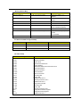
Revision History
Please refer to the table below for the updates made on Aspire T650/E500 and AcerPower F5 service guide.
Date
II
Chapter
Updates
Copyright
Copyright © 2005 by Acer Incorporated. All rights reserved. No part of this publication may be reproduced,
transmitted, transcribed, stored in a retrieval system, or translated into any language or computer language, in
any form or by any means, electronic, mechanical, magnetic, optical, chemical, manual or otherwise, without
the prior written permission of Acer Incorporated.
Disclaimer
The information in this guide is subject to change without notice.
Acer Incorporated makes no representations or warranties, either expressed or implied, with respect to the
contents hereof and specifically disclaims any warranties of merchantability or fitness for any particular
purpose. Any Acer Incorporated software described in this manual is sold or licensed "as is". Should the
programs prove defective following their purchase, the buyer (and not Acer Incorporated, its distributor, or its
dealer) assumes the entire cost of all necessary servicing, repair, and any incidental or consequential
damages resulting from any defect in the software.
Acer is a registered trademark of Acer Corporation.
Intel is a registered trademark of Intel Corporation.
Pentium 4 and Celeron are trademarks of Intel Corporation.
Other brand and product names are trademarks and/or registered trademarks of their respective holders.
III
Conventions
The following conventions are used in this manual:
IV
SCREEN
MESSAGES
Denotes actual messages that appear
on screen.
NOTE
Gives bits and pieces of additional
information related to the current
topic.
WARNING
Alerts you to any damage that might
result from doing or not doing specific
actions.
CAUTION
Gives precautionary measures to
avoid possible hardware or software
problems.
IMPORTANT
Reminds you to do specific actions
relevant to the accomplishment of
procedures.
Preface
Before using this information and the product it supports, please read the following general information.
1.
This Service Guide provides you with all technical information relating to the BASIC CONFIGURATION
decided for Acer's "global" product offering. To better fit local market requirements and enhance product
competitiveness, your regional office MAY have decided to extend the functionality of a machine (e.g.
add-on card, modem, or extra memory capability). These LOCALIZED FEATURES will NOT be covered
in this generic service guide. In such cases, please contact your regional offices or the responsible
personnel/channel to provide you with further technical details.
2.
Please note WHEN ORDERING FRU PARTS, that you should check the most up-to-date information
available on your regional web or channel. If, for whatever reason, a part number change is made, it will
not be noted in the printed Service Guide. For ACER-AUTHORIZED SERVICE PROVIDERS, your Acer
office may have a DIFFERENT part number code to those given in the FRU list of this printed Service
Guide. You MUST use the list provided by your regional Acer office to order FRU parts for repair and
service of customer machines.
V
Chapter 1 System Specifications.......................................................1
Overview . . . . . . . . . . . . . . . . . . . . . . . . . . . . . . . . . . . . . . . . . 1
Features . . . . . . . . . . . . . . . . . . . . . . . . . . . . . . . . . . . . . . . . . 4
Block Diagram . . . . . . . . . . . . . . . . . . . . . . . . . . . . . . . . . . . . . 7
MainBoard Placement . . . . . . . . . . . . . . . . . . . . . . . . . . . . . . 8
Rear I/O Port . . . . . . . . . . . . . . . . . . . . . . . . . . . . . . . . . . . . . 10
Jumper and Connector Setting . . . . . . . . . . . . . . . . . . . . . . . 11
Connector Information . . . . . . . . . . . . . . . . . . . . . . . . . . . . . 12
Aspire T650 Front Panel . . . . . . . . . . . . . . . . . . . . . . . . . . . . 17
Aspire E500 Front Pane . . . . . . . . . . . . . . . . . . . . . . . . . . . . 18
AcerPower F5 Front Panel . . . . . . . . . . . . . . . . . . . . . . . . . . 19
Aspire T650/E500, AcerPower F5 Rear Panel . . . . . . . . . . . 20
System Peripherals . . . . . . . . . . . . . . . . . . . . . . . . . . . . . . . . 21
Acer eRecovery . . . . . . . . . . . . . . . . . . . . . . . . . . . . . . . . . . 23
Acer disc-to-disc recovery . . . . . . . . . . . . . . . . . . . . . . . . . . 25
Hardware Specifications and Configurations . . . . . . . . . . . . 26
Power Management Function (ACPI support function) . . . . 33
Chapter 2 System Utilities..............................................................35
Entering Setup . . . . . . . . . . . . . . . . . . . . . . . . . . . . . . . . . . .
Product Information . . . . . . . . . . . . . . . . . . . . . . . . . . . . . . .
Standard CMOS Features . . . . . . . . . . . . . . . . . . . . . . . . . .
Primary IDE Master . . . . . . . . . . . . . . . . . . . . . . . . . . . . . . .
Advanced BIOS Features . . . . . . . . . . . . . . . . . . . . . . . . . . .
Advanced Chipset Features . . . . . . . . . . . . . . . . . . . . . . . . .
Integrated Peripherals . . . . . . . . . . . . . . . . . . . . . . . . . . . . .
Power Management Setup . . . . . . . . . . . . . . . . . . . . . . . . . .
PnP/PCI Configuration . . . . . . . . . . . . . . . . . . . . . . . . . . . . .
PC Health Status . . . . . . . . . . . . . . . . . . . . . . . . . . . . . . . . . .
Frequency Control . . . . . . . . . . . . . . . . . . . . . . . . . . . . . . . . .
Load Default Settings . . . . . . . . . . . . . . . . . . . . . . . . . . . . . .
Set Supervisor/User Password . . . . . . . . . . . . . . . . . . . . . . .
Save & Exit Setup . . . . . . . . . . . . . . . . . . . . . . . . . . . . . . . . .
Exit Without Saving . . . . . . . . . . . . . . . . . . . . . . . . . . . . . . . .
36
37
38
40
41
43
44
46
48
49
50
51
52
53
54
Chapter 3 Machine Disassembly and Replacement......................55
General Information . . . . . . . . . . . . . . . . . . . . . . . . . . . . . . . 56
Disassembly Procedure . . . . . . . . . . . . . . . . . . . . . . . . . . . . 57
Aspire T650 Standard Disassembly Procedure . . . . . . . . . . 58
Aspire T650 Standard Reassembly Procedure . . . . . . . . . . 66
Aspire E500 Standard Disassembly Procedure . . . . . . . . . . 75
Aspire E500 Standard Reassembly Procedure . . . . . . . . . . 83
AcerPower F5 Standard Disassembly Procedure . . . . . . . . 92
AcerPower F5 Standard Reassembly Procedure . . . . . . . . 100
Chapter 4 FRU(Field Replaceable Unit) List...............................109
Aspire E500/T650 Exploded Diagram . . . . . . . . . . . . . . . . 110
AcerPower F5 Exploded Diagram . . . . . . . . . . . . . . . . . . . 112
1
2
Chapter 1
System Specifications
Overview
All the new Socket-T motherboards come with a socket protector that has to be removed before you
fit the CPU. This is to prevent damage to the pins inside the CPU socket before the chip is inserted.
The new CPU socket is known as Socket-T and the new processors will be of LGA775 type. LGA stands
forLand Grid Array and means that there are no pins on the bottom of the CPU, although there are still contact
surfaces - no less 775 of them. The CPU interface has been moved to the mainboard socket and this is a
way for Intel to get fewer returns in terms of damaged CPUs due to bent or broken pins.
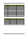
These two models (Aspire T650/E500 & AcerPower F5) use ATI on die VGA chipset to address the overall
platform graphic performance. We provide the most time-to-market specification:
T
Support Intel 775 pin mainstream CPU up to P4 4.0Ghz/FSB 800
T
On board ATI VGA performed great graphic power than previous AGP 8X
T
Add-On PCI-Express VGA card provides extra graphic solution for extensive gamers
T
DDR II memory with dual channel provides faster processing speed and efficiency
Aspire T650/E500 will be the product name for consumer market. AcerPower F5 will be the product name
for commercial market. Please refer below table for more details address toward each chipset that be used in
this project : (It’s only for reference as guideline)
Chipset
ATI RC410 Express chipset
Chapter 1
General Features
T
64-bit single-channel DDR/DDR2 SDRAM interface
T
SUpports one PCI Express x16 for Graphics Interface,
fully compliant to the PCI Express Base Specification
revision 1.0a
T
Full support for 3D primitive, Direct3D texture lighting,
and OpenGL format for Indirect Vertices in Vertex
Walker
T
Full DirectX 9.0 support(Vertex Shader version 2.0 and
Pixel shader version 2.0)
1
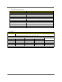
Chipset
ULI M1573
REALTEK ALC880 Controller
Marvell 8EE8001 GigaLAN
ITE IT8712 Controller
2
General Features
T
Provides a High Integration Bridge
T
One EHCI USB 2.0 and three OHCI USB 1.1 Host
Controllers for supporting up to eight USB ports
T
Supports HS (480Mbits/sec), FS (12Mbits/sec) and LS
(1.5Mbits/sec) data transfer rate
T
Provides High Definition(HD) Audio/AC'97 2.3
compliant digital controller interface for third parties
(such as the AMC Codec's vendor) to enable the
software modem solution
T
Provides 1/10/100 Mbps Medium Access Control
(MAC) controller for the best solution of the phone-line/
Ethernet LAN connectivity
T
Supports SATA 1.0 (High Speed Serialized AT
Attachment, Revision 1.0a), 1.5 Gb/s data rate
T
High-performance DACs with 100dB S/N ratio
T
ADCs with S/N ratio greater than 85dB
T
8 DAC channels support 16/20/24-bit PCM format for
7.1 audio solution
T
Supports 44.1K/48K/86K/192KHz DAC sample rate
T
All ADCs support 44.1K/48K/96K sample rate
T
-64dB ~ +30dB with 1dB resolution of mixer gain to
achieve finer volume control
T
Emulation of 26 sound environments to enhance
gaming experience
T
10 Software Equalizer Bands
T
Integrated 10/100/1000 transceiver
T
Wake-on-LAN and remote wake-up support
T
Fully compliant with IEEE 802.3, IEEE 802.3u, IEEE
802.3ab
T
Supports IEEE 802.1Q VLAN tagging
T
Supports up to 1/240 duty cycle
T
Provides 320 LCD drive circuits
T
Provides 2.6 to 5.5V LCD drive voltage
T
Provides 2.5 to 5.5V operating voltage
T
Provides 4-bit or 8-bit parallel data input
T
Supports screen display off function
T
Supports the automatic generation of chip enable sign
T
Supports Power standby function
T
Package : Flex-TCP /can also be shipped in CHI (433
bumps)
T
Maximum shirt clock frequency : 6.5 MHz (VCC=3V)/8
MHz (VCC=5V)
T
Two output modes are selectable : 320 output mode/
240 output mode
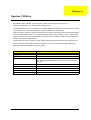
Chapter 1
Remark: ULI M1573 ( for reference)
The M1573 integrates a High Definition (HD) Audio/AC'97 Host Controller, 2-channel dedicated Ultra-66/100/
133 IDE Master controller, SATA Host Controller (4 SATA ports that can support SATA RAID 0,1,0+1)
supporting Native Command Queue, USB 2.0/1.1 Host controllers, IO APIC controller, as well as 1/10/100 Mb/
s Fast Ethernet MAC layer and PCI Express interface.
Of most interest in the HD Audio feature, which is an Intel Azalia Compliant Audio Solution. Azalia is the next
generation of onboard audio, and is very advanced. Essentially, it provides superior Audio Onboard, negating
the need for an expensive 3rd party audio card. (copyright by OCW)
Chapter 1
3
Features
CPU
T
Socket Type : Intel Socket T
T
Supports Intel Pentium D FSB 800MHZ
T
Supports Intel Pentium 4 Prescott 775 / FSB 533/800MHz
T
Supports Intel Celeron Prescott 775 / FSB 533MHz
T
Pentium 4 2.66GHz ~3.8GHz speed
T
Celeron D2.80GHz ~ 3.06GHz
T
L2 Cache varies with CPU from 1MB to 2MB (for 6xx series CPU)
Chipset
T
Northbridge: ATI RC410
T
Southbridge: ULI M1573
Memory
T
Socket Type : DDR II,1.8 Voltage
T
Socket Quantity : 2
T
Capacity support : 256MB ~ 2GB
T
Support Memory Speed : 400/533 MHz
Graphic Solution
T
ATI RC410 on-die graphic solution
T
PCI-E x16 VGA Add-On Card
Slots
T
1 PCI Express x16 slot
T
1 PCI Express x1 slot
T
2 PCI 2.3 5V slots
T
One 1.44MB 3.5” device
T
Slot Type : 40pin PATA IDE slot
T
Slot Quantity : 2
T
Transfer rate support PIO mode 0 (3.33MB/s) /1 (5.22MB/s) /2 (8.33MB/s) /3 (11.1MB/s) /
FDD
IDE
4 (16.7MB/s)
4
T
ATA mode : 33/66/100/133
T
Device Type Support : HDD/CD-ROM/DVD-ROM/Combo/DVD burner
T
Connector Type : SATA IDE Connector
T
Connector Quantity : 2
T
Storage Type Support : HDD
Chapter 1
Audio
T
Codec : Realtek ALC880 (HD Codec)
T
One UAJ (Universal Audio Jack) support (rear only)
Remark UAJ : UAJ not only provides the ideal solution for multi-media and also user-friendliness for audio
speaker installation.
T
5.1 Channel Audio Support
T
Reserved disable function on BIOS side. Default is enabled.
T
Controller : ULI M1573 compatible
T
LAN Chip : Marvell 8EE8001
T
Should be worked under 10/100/1000 Mbs environment
T
Reserved disabled function on both hardware & BIOS side. Default is enabled
T
Controller : ULI M1573 compatible
T
Connectors Quantity : 8 (four on rear connector, four on-board header)
T
2 for front daughter board (Pin:2*5 Intel FPIO)
T
1 for Multi-Media card reader (Pin : 1*5)
T
USB 2.0/1.1
LAN
USB
System LED Definition
LED Item
Color
Power state LED
S0
Green Steady
S1/S3
Amber Steady
S4/S5
Off
HDD state LED
IDE active
Green Blinking
IDE idle
Off
LAN state LED
LAN active
Green Blinking
LAN idle
Off
On-Board Connector
T
Chapter 1
Rear I/O Connectors
T
1 PS/2 Keyboard Port, 1 PS/2 Mouse Port
T
1 Parallel Port, 1 Serial Port
T
1 VGA Port
T
1 GigaLAN Port
T
4 USB Ports
T
6 Ports Jack Support HD (High Definition) Audio Output
T
1 IEEE 1394 port
5
T
6
On-Board Connectors
T
1 CPU Socket
T
2 Memory Socket
T
1 PCI Express x1 Slot
T
1 PCI Express x16 Slot
T
2 PCI Slots
T
1 FDD Slot
T
2 PATA IDE Slots
T
2 SATA IDE Slots
T
1 2*5 pin Intel FPIO sepecification USB pin connectors
T
3 1*5 pin USB pin connector
T
1 2nd serial port
T
1 CD-In 4pin connector (CD-ROM Audio Input)
T
1 3/4 pin CPU Fan connector
T
1 3 pin System FAN connectors
T
1 24pin/4pin ATX interface PS3/PS2 SPS connector
T
1 2*4pin Intel FPIO specification Power Switch/Power State LED/HDD active LED
T
1 2 pin LAN activity monitor connector
T
2 reserved 2pin GPIO connector
T
Color management for on board connector
Chapter 1
Chapter 1
22
USB-7
OTHER DC POWER
4
3
22
USB-4
PCI SLOT 2
21
22
USB-5
CPU CORE POWER
22
USB-6
PCI SLOT 1
19
USB-3
21
PCI BUS
20
22
USB-1
IEEE 1394
19
USB-2
PCIE GFX x1
PCIE GFX x16
VGA CON
13
13
23
EXTERNAL CLOCK
GENERATOR
2
18
LPT
23
18
SERIAL
KBD
MOUSE PORT
22
23
ITE LPC SIO 8712F/IX
LPC BUS
14,15,16,17
PCI/PCI BDGE
LPC I/F
ACPI 2.0
ATA 66/100/133
AC97 2.3
AZALIA
SATA (4 PORTS)
USB2.0 (4+4)
ULI SB - M1573
X4
PCIE
7,8,9,10
4 X1 PCIE I/F
1 X2 PCIE I/F WITH SB
1 X16 PCIE VIDEO I/F
TVOUT/TMDS
INTEGRATED GRAPHICS
X1 DDR CHANNEL
AGTL+ P4 CPU I/F
FLOPPY
USB 2.0
Gbit/100/10M
ETHERNET
19
22
USB-0
PCIE x1
PCIE x16
CRT
AGTL+
200MHz
ATI NB - RC410
2X ADDRESS
4X DATA
DESKTOP PRESCOTT
SOCKET LGA775 5,6
FLASH
BIOS
18
ATA 66/100/133
SERIAL ATA
AC LINK
A CHANNEL
DDR II 400/533/667
22
IDE2
22
17
IDE1
SATA#2
17
24,25
SATA#1
AZALIA
240-PIN DDR II DIMM
UNBUFFERED
DDR2 DIMM
11
240-PIN DDR II DIMM
UNBUFFERED
DDR2 DIMM
11
17
SATA#3
17
SATA#4
Block Diagram
7
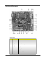
MainBoard Placement
Mainboard Items
Item
8
Label
Description
1
CPU Socket
LGA775 socket for Pentium 4 CPUs
2
DIMM1,2
240-pin DDR2 SDRAM slots
3
IR1
Infrared header
4
CPU_FAN
CPU cooling fan connector
5
ATX_POWER
Standard 24-pin ATX power connector
6
BIOS_TBL
BIOS Prevent header
7
BIOS_WP
BIOS protection jumper
8
FDD
Floppy diskette drive connector
9
IDE2
Secondary IDE channel
10
IDE1
Primary IDE channel
11
TBD
TBD
12
CLR_CMOS
Clear CMOS jumper
13
SATA1~4
Serial ATA connectors
14
CASE_FAN
Case cooling fan connector
Chapter 1
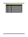
Mainboard Items
Item
Chapter 1
Label
Description
15
PANEL1
Front panel switch/LED header
16
USB3,4
Front Panel USB header
17
1394A2
Onboard 1394a header (optional)
18
COM2
Onboard serial port header
19
SPDIFO1
SPDIF out header
20
CD_IN
Analog audio input connector
21
AUDIO1
Front panel audio header
22
PCI1~2
32-bit add-on card slots
23
PCIE1
PCI Express x1 slot
24
PCIEX16
PCI Express x16 graphics card slot
25
SYS_FAN
System cooling fan connector
26
ATX12V
4-pin +12V power connector
9
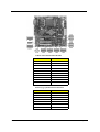
Rear I/O Port
Item
Description
PS/2 Keyboard and PS/2 Mouse
Connector
To install a PS/2 port keyboard and mouse, plug the mouse to the
upper port (green) and the keyboard to the ower port (purple).
Parallel Port(LPT1)
The parallel port allows connection of a printer, scanner and other
peripheral devices.
Serial Port(COM1)
Connects to serial-based mouse or data processing devices.
VGA Port
Monitor can be connected to VGA port.
USB Ports
Before you connect your device(s) into USB connector(s), please
make sure your device(s) such as USB keyboard, mouse, scanner,
zip, speaker...etc. have a standard USB interface. Also make sure
your OS supports USB controller. If your OS does not support USB
controller, please contact OS vendor for possible patch or driver
upgrade. For more information please contact your OS or device(s)
vendors.
LAN Port
The provided Internet connection is Gigabit Ethernet, providing data
transfer speeds of 10/100/1000Mbps.
1394a Port
Use the 1394a port to connect andy 1394a device
Audio Ports
Use the audio jacks to connect audio devices. The D port is for stereo
line-in signal, while the F port is for microphone in signal. This
motherboard supports 8-channel audio devices that correspond to the
A, B, C, and E port respectively. In addition, all of the 3 ports, B, C,
and E provide users with both right&left channels individually. Users
please refer to the following note for specific port function definition.
A: Center&Woofer
B: Back Surround
C: Side Surround
D: Line-in
E: Front Out
F: Mic-in Rear
NOTE: The above port definition can be changed to audio
input or audio output by changing the driver utility
setting.
10
Chapter 1
Jumper and Connector Setting
Jumper Setting
Jumper
CLR_CMOS
Type
3-pin Description
CLEAR CMOS
Setting
1-2: Normal
2-3: Clear CMOS
Before clearing the CMOS, make
sure to turn off the system.
BIOS_WP
3-pin
BIOS PROTECT
1-2: DISABLE
2-3: ENABLE
BIOS_TBL
3-pin
BIOS PREVENT
1-2: DISABLE
2-3: ENABLE
Chapter 1
11
Connector Information
CPU_FAN/SYS_FAN/CASE FAN
Illustration
Pin No.
1
CPU_FAN
Definition
1
GND
2
+12V
3
Sense
4
Speed Control (Only for CPU Fan)
1
SYS_FAN
ATX12V
Illustrator
12
PIN No.
3
4
1
2
Definition
1
GND
2
GND
3
+12V
4
+12V
Chapter 1
ATX Power
PIN
No.
Illustration
13
1
12
24
PIN
No.
Definition
Definition
1
3.3V
13
3.3V
2
3.3V
14
-12V
3
GND
15
GND
4
+5V
16
PS_ON(soft On/Off)
5
GND
17
GND
6
+5V
18
GND
7
GND
19
GND
8
Power Good
20
-5V
9
5V SB(stand by +5V)
21
+5V
10
+12V
22
+5V
11
+12V
23
+5V
12
3.3V(Only for 24pins
ATX)
24
GND
ATX Power
PIN
No.
Illustration
Chapter 1
PIN
No.
Definition
Definition
1
Hard disk LED(+)
8
Power Switch(-)
2
MSG LED(+)
9
Reserved
3
Hard disk LED(-)
10
Key
4
MSG LED(-)
11
ODD LED(+)
5
Reset Switch(-)
12
LAN LED
6
Power Switch(+)
13
ODD LED(-)
7
Reset Switch(+)
14
LAN LED(-)
13
Audio1:Front Panel Audio Header
Pin No.
Definition
1
PORT-FL
2
GND
3
PORT-FR
4
ACZ-DET
5
PORT-ER
6
AGND
7
SENSE B
8
NO PIN
9
PORT-EL
10
GND
SATA1/2/3/4: Serial ATA connectors
Pin No.
14
Definition
1
Ground
2
TX+
3
TX-
4
Ground
5
RX-
6
RX+
7
Ground
Chapter 1
SPDIFO1:SPDIF out header
Pin No.
Definition
1
5V analog power
2
No pin
3
SPDIF digital output
4
Ground
1394A2: Onboard IEEE 1394a headers(optional)
Pin No.
Definition
1
TPA+
2
TPA-
3
GND
4
GND
5
TPB+
6
TPB-
7
Cable-Power
8
Cable-Power
9
Key Pin
10
GND
USB3/4: Front Panel USB header
Pin No.
Defintion
1
Power
2
Power
3
USB_FP_P0-
4
USB_FP_P1-
5
USB_FP_P0+
6
USB_FP_P1+
7
GND
8
GND
9
No Pin
10
USB_FP_OC0
(Overcurrent signal)
COM2: Onboard serial port header(optional)
Pin
1
Chapter 1
Signal Name
NDCDB
Definition
Data carry detect
2
NSINB
Serial Data In
3
NSOUTB
Serial Data Out
4
NDTRB
Data terminal ready
5
GND
Ground
6
NDSRB
Date set ready
15
COM2: Onboard serial port header(optional)
Pin
Signal Name
Definition
7
NRTSB
Request to send
8
NCTSB
Clear
9
NRIB
Ring Indicator
10
KEY
Key
CD_IN: Analog audio input header
Pin
Signal Name
Definition
1
CD in_L
CD In left channel
2
GND
Ground
3
GND
Ground
4
CD in_R
CD In right channel
IR1: Infrared port
Pin
16
Signal Name
Definition
1
NC
Not connected
2
Key
No pin
3
+5V
IR Power
4
GND
Ground
5
IRTX
IrDA serial output
6
IRRX
IrDA serial input
Chapter 1
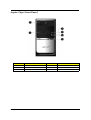
Aspire T650 Front Panel
No.
Chapter 1
Description
No.
Description
1
Optical Device
2
Floppy drive
3
Power Button
4
Microphone Jack
5
Speaker/Headphone Jjack
6
USB Ports
17
Aspire E500 Front Panel
No.
Description
No.
2
Description
1
Optical Driver
Optical Drive Eject Button
3
Power Button
4
USB Ports
5
Speaker/Headphone Jack
6
Microphone-in Jack
7
Indicators
8
Floppy Disk Drive
9
Card Reader
10
IEEE 1394 Port
NOTE: The picture left is the front bezel with middle cover slided down.
18
Chapter 1
AcerPower F5 Front Panel
No.
Chapter 1
Description
No.
2
Description
1
Optical Drive
Floppy Disk Drive
3
Card Reader
4
Indicators
5
USB Ports
6
Microphone-inJack
7
Speaker/HeadphoneJack
8
Power Button
19
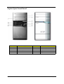
Aspire T650/E500, AcerPower F5 Rear Panel
No.
Description
No.
Description
1
Power Supply
2
Power Cord Socket
3
Voltage Select Switch
4
PS/2 Mouse Port
5
PS/2 Keyboard Port
6
Serial Port
7
Printer Port
8
Monitor Connector
9
USB Ports
10
RJ45 port
11
Audio Jack
12
Expansion Slots
13
Chassis Lock Pad
14
SPDIF port
15
N/A
NOTE: The IEEE 1394 port is an optional item.
20
Chapter 1
System Peripherals
The Aspire T630 and AcerPower F3 computer consist of the system itself, and system peripherals, like a
mouse, keyboard and a set of speakers (optional). This section provides a brief description of the basic
system peripherals.
Mouse (PS/2 or USB, manufacturing option)
The included mouse is a standard two-button wheel mouse. Connect the mouse to the PS/2 mouse port or
USB port on the back panel of the system.
Keyboard (PS/2 or USB, manufacturing option)
Connect the keyboard to the PS/2 keyboard port or USB port on the back panel of the system.
Chapter 1
21
Speakers
Note:
For systems bundled with speakers, before powering on the system, connect the speaker cable to the audio
out (external speaker) port on the back panel of the system.
For more detailed information about the speakers, please refer to the included operating instructions.
NOTE: speakers are optional and the appearance might be different depending on the actual product.
22
Chapter 1
Acer eRecovery
Acer eRecovery is a tool to quickly backup and restore the system. Users can create and save a
backup of the current system configuration to hard drive, CD, or DVD.
Acer eRecovery consists of the following functions:
1.
Create backup
2.
Restore from backup
3.
Create factory default image CD
4.
Re-install bundled software without CD
5.
Change Acer eRecovery password
Create backup
Users can create and save backup images to hard drive, CD, or DVD.
1.
Boot to Windows XP
2.
Press <Alt>+<F10> to open the Acer eRecovery utility.
3.
Enter the password to proceed. The default password is six zeros.
4.
In the Acer eRecovery window, select Recovery settings and click Next
5.
In the Recovery settings window, select Backup snapshot image and click Next.
6.
Select the backup method.
T
Use Backup to HDD to store the backup disc image on drive D:.
T
Backup to optical device to store the backup disc image on CD or DVD (only available on
systems that include an optical disc burner).
7.
After choosing the backup method, click Next.
Follow the instruction on screen to complete the process.
Restore from backup
Users can restore backup previously created (as stated in the Create backup section) from hard drive,
CD, or DVD.
1.
Boot to Windows XP.
2.
Press <Alt>+<F10> to open the Acer eRecovery utility.
3.
Enter the password to proceed. The default password is six zeros.
4.
In the Acer eRecovery window, select Recovery actions and click Next.
5.
Select the desired restore action and follow the onscreen instructions to complete the restore process.
Create factory default image CD
When the System CD and Recovery CD are not available, you can create them by using this feature.
1.
Boot to Windows XP.
2.
Press <Alt>+<F10> to open the Acer eRecovery utility.
3.
Enter the password to proceed. The default password is six zeros.
4.
In the Acer eRecovery window, select Recovery settings and click Next.
5.
In the Recovery settings window, select Burn image to disc and click Next.
6.
In the Burn image to disc window, select 01. Factory default image and click Next.
Chapter 1
23
7.
Follow the instructions on screen to complete the process.
Re-install bundled software without CD
Acer eRecovery stores pre-loaded software internally for easy driver and application re-installation.
1.
Boot to Windows XP.
2.
Press <Alt>+<F10> to open the Acer eRecovery utility.
3.
Enter the password to proceed. The default password is six zeros.
4.
In the Acer eRecovery window, select Recovery actions and click Next.
5.
In the Recovery settings window, select Reinstall applications/drivers and click Next.
6.
Select the desired driver/application and follow the instructions on screen to re-install.
At first launch, Acer eRecovery prepares all the needed software and may take few seconds to bring up the
software content window.
Change Password
Acer eRecovery and Acer disc-to-disc recovery are protected by a password that can be changed by
the user. Follow the steps below to change the password in Acer eRecovery.
24
1.
Boot to Windows XP.
2.
Press <Alt>+<F10> to open the Acer eRecovery utility.
3.
Enter the password to proceed. The default password is six zeros.
4.
In the Acer eRecovery window, select Recovery settings and click Next.
5.
In the Recovery settings window, select Password: Change Acer eRecovery password and click Next.
6.
Follow the instructions on screen to complete the process.
Chapter 1
Acer disc-to-disc recovery
Restore without a Recovery CD
This recovery process helps you restore the C: drive with the original software content that is installed when
you purchase your notebook. Follow the steps below to rebuild your C: drive. (Your C: drive will be
reformatted and all data will be erased.) It is important to back up all data files before you use this option.
1.
Restart the system.
2.
While the Acer logo is showing, press <Alt>+<F10> at the same time to enter the recovery process.
3.
The message "The system has password protection. Please enter 000000:" is displayed.
4.
Enter six zeros and continue.
5.
The Acer Recovery main page appears.
6.
Use the arrow keys to scroll through the items (operating system versions) and press <Enter> to select.
Multilingual operating system installation
Follow the instructions to choose the operating system and language you prefer when you first power-on the
system.
1.
Turn on the system.
2.
Acer's multilingual operating system selection menu will pop-up automatically.
3.
Use the arrow keys to scroll to the language version you want. Press <Enter> to confirm your selection.
4.
The operating system and language you choose now will be the only option for future recovery
operations.
5.
The system will install the operating system and language you choose.
Chapter 1
25
Hardware Specifications and Configurations
System Board Major Chip
Item
Specification
System Core Logic
ATI RC410
ULI M1573
Super I/O Controller
ITE 8712
LAN Controller
Marvell 8EE8001
Memory Controller
Build in ATI RC410
E-IDE Controller
Build in ULI M1573
RJ45 Controller
RTL 8110S
Audio Controller
ULI M1573
VGA Controller
ATI RC410
Keyboard Controller
ITE 8712
Processor
Item
Specification
Type
Intel Pentium 4 processor 775 Land Grid Array(LGA)
Slot
Socket-T (LGA 775)
Speed
Depends on CPU, which is local configured
Bus Frequency
533/800 MHz
Voltage
Processor voltage can be detected by any system without
setting any jumper
BIOS
Item
Specification
BIOS code programmer
AMI
BIOS version
R01-A0
BIOS ROM size
4MB
BIOS ROM package
32-pin PLCC package
Support protocol
PCIX 1.0,PCI 2.2,APM 1.2,VESA/DPMS (VBE/PM V1.1),
SMBIOS 2.3, E-IDE 1.1, ACPI 1.0b,ESCD1.03, PnP 1.0a,
Bootable CD-ROM 1.0, USB 1.1~ USB 2.0, UHCI 1.0, ANSI
ATA 3.0 ATAPI
Boot from CD-ROM feature
Yes
Support to LS-120 drive
Yes
Support to BIOS boot block feature
Yes
BIOS Password Control
Yes
BIOS Hotkey List
Hotkey
c
26
Function
Enter BIOS Setup Utility
Description
Press while the system is booting to
enter BIOS Setup Utility.
Chapter 1
System Memory
Item
Specification
Memory Slot Number
2 Slots
Supported Memory Size per Slot
256 MB ~ 1GB
Supported Maximum Memory Size
2GB
Supported Memory Speed
400/533/667 MHz
Supported memory voltage
1.8 V
Support memory module package
240-pin DIMM
Support to parity check feature
Yes
Support to Error Correction Code (ECC)
feature
Yes
Memory module combinations
You can install memory modules in any combination as
long as they match the above specifications.
VRM (Voltage Regulator Module)
Function
VRM Specification
Typical Voltage
Power Source
Maximum Output
CPU VRM
VRM10.1
0.8375~1.6v
12 Voltage
101A
CPU VRM
VRM 9.0
1.1-1.85 Voltage
12 Voltage
70A
Cache Memory
Item
Specification
First-Level Cache Configurations
Cache function control
Enable/Disable by BIOS Setup
Second-Level Cache Configurations
The information below is only applicable to system installed with a Pentium 4 processor
Tag RAM Location
On Processor
L2 Cache RAM Location
On Processor
L2 Cache RAM type
PBSRAM (Pipelined-burst Synchronous RAM)
L2 Cache RAM size
Depends on CPU, which is local configured
L2 Cache RAM speed
Full of the processor core clock frequency (Advanced Transfer Cache)
L2 Cache function control
Enable/Disable by BIOS Setup
L2 Cache scheme
Fixed in write-back
LAN Interface
Item
Specification
LAN Controller
Marvell 8EE8001 GigaLAN Controllers
LAN Controller Resident Bus
PCI Bus
LAN Port
ONE RJ-45 on board
Function Control
Enable/Disable by BIOS Setup
Chapter 1
27
IDE Interface
Item
Specification
IDE Controller
Built-in ULi M1573
IDE Controller Resident Bus
PCI bus
Number 40 pin PATA slot
2
T
Device Type Support
T
Transfer Rate Support
PIO 0/1/2/3/4
T
ATA Mode
33/66/100/133
Number STAT IDE slot
T
HDD, CD-ROM, CD-RW, DVD-ROM,Combo,DVD burner
2
Device Type Support
HDD
Supports LS-120
Yes
Supports bootable CD-ROM
Yes
Function Control
Enable/Disable by BIOS setup
Diskette Drive Interface
Item
Specification
Diskette Drive Controller
ULi M1573
Diskette Drive Controller Resident Bus
LPC Bus
Supported Diskette Drive Formats
1.44MB, 2.88MB format and slim type diskette drive
Function Control
Enable/Disable by BIOS Setup
Serial Port
Item
Specification
Serial port controller
Build-in ITE 8712
Serial port controller resident bus
LPC Bus
Number of serial port
1
Serial port location
Rear Panel
16550 UART support
Yes
Connector type
9-pin D-type female connector
Optional serial port I/O address
(via BIOS Setup)
3F8h
2F8h
3E8h
2E8h
Optional serial port IRQ
(via BIOS Setup)
IRQ4
IRQ3
USB Port
Item
Universal HCI
28
Specification
USB 2.0/1.1
Controller
ULi M1573
Number of the connectors
8
Chapter 1
USB Port
Item
Specification
Location
Rear : 4
On-board header : 4
USB Class
Support legacy keyboard for legacy mode
Wake-up Event Specifications
Device
S1
S3
S4
S5
Power Button
Enabled
Enabled
Enabled
Enabled
PS2 Keyboard
Enabled
Disabled
Enabled
Enabled
USB Keyboard
Enabled
Enabled
Disabled
Enabled
LAN
Disabled
Disabled
Disabled
Disabled
WOR (wake on Ring)
Disabled
Disabled
Disabled
Disabled
RTC (real time clock)
Disabled
Disabled
Disabled
Disabled
Thermal Design
Item
Description
Thermal Design
T
T
Dynamic FAN speed control by hardware monitor
CPU Over-temperature (over 120oC) power off
protection.
Power On / Wake-up Event
Item
Power On/ Wake-Up Event
Description
T
Power Button: S1/S3/S4/S5
T
PS/2 Keyboard: S1/S3/S4/S5
T
USB Keyboard: S1/S3/S4/S5
T
RTC: S1/S5
T
LAN: S1/S3/S5
T
Modem (Ring): S1/S3/S5
Memory Address Map
Address
Size
Function
0000000 - 009FFFF
640 KB System Memory
Onboard DRAM
00A0000-00BFFFF
128 KB Video RAM
Reserved for Graphics Display
Buffer
Non-Cacheable
00C0000-00CFFFF
32 KB I/O Expansion ROM
Reserved for ROM on I/O
Adapters
00D0000-00D3FFF
16 KB I/O Expansion ROM
Reserved for ROM on I/O
Adapters
00D4000-00D7FFF
16 KB I/O Expansion ROM
Reserved for ROM on I/O
Adapters
Chapter 1
29
Memory Address Map
Address
Size
Function
00D8000-00DBFFF
16 KB I/O Expansion ROM
Reserved for ROM on I/O
Adapters
00DC000-00DFFFF
16 KB I/O Expansion ROM
Reserved for ROM on I/O
Adapters
00E0000-00E7FFF
32 KB for SCSI BIOS
Reserved for SCSI BIOS
00E8000-00EFFFF
32 KB
Reserved Onboard
00F0000-00FFFFF
64 KB BIOS
System ROM BIOS (ROM)
System RAM BIOS (DRAM)
0100000-0F9FFFF
System Memory
Onboard DRAM
0FA0000-0FFFFFF
384 KB I/O Card Memory
Reserved for Memory Map
I/O Card
Non-Cacheable
1000000-FFFFFFF
System Memory
Onboard DRAM
PCI INTx# and IDSEL Assignment Map
PCI INTx #
PCI Devices
Device IDSEL: ADxx
INTA#
ADIMM-slot
N
INTB#
PCI-Slot1
AD16
INTC#
PCI-Slot2
AD17
I/O Address Map
Hex Range
000-01F
020-021
040-043
060-060
061-061
070-071
080-08F
0A0-0A1
0C0-0DF
0F0-0FF
170-177
1F0-1F7
278-27F
2F8-2FF
378-37F
3F0-3F5
3F6-3F6
3F7-3F7
3F8-3FF
0CF8
0CFC
778-77A
30
Devices
DMA Controller-1
Interrupt Controller-1
System Timer
Keyboard Controller 8742
System Speaker
CMOS RAM Address and Real Time Clock
DMA Page Register
Interrupt Controller-2
DMA Controller-2
Math Co-Processor
Secondary IDE
Primary IDE
Parallel Printer Port 2
Serial Asynchronous Port 2
Parallel Printer Port 1
Floppy Disk Controller
Secondary IDE
Primary IDE
Serial Asynchronous Port 1
Configuration Address Register
Configuration Data Register
Parallel Printer Port 1
Chapter 1
IRQ Assignment Map
IRQx
System Devices
Add-On-Card Devices
IRQ0
Timer
N
IRQ1
Keyboard
N
IRQ2
Reserved
N
IRQ3
Serial Port 2
Reserved
IRQ4
Serial Port 1
Reserved
IRQ5
Reserved
Reserved
IRQ6
Floppy Disk
Reserved
IRQ7
Parallel Port
Reserved
IRQ8
Real Time Clock
N
IRQ9
N
Reserved
IRQ10
N
Reserved
IRQ11
N
Reserved
IRQ12
PS/2 Mouse
Reserved
IRQ13
Numeric Processor
N
IRQ14
Embedded Hard Disk
Reserved
IRQ15
Reserved
Reserved
NOTE: N - Not be used
DRQ Assignment Map
DRQx
System Devices
Add-On-Card Devices
DRQ0
N
Reserved
DRQ1
N
Reserved
DRQ2
FDD
N
DRQ3
N
Reserved
DRQ4
Cascade
N
DRQ5
N
Reserved
DRQ6
N
Reserved
DRQ7
N
Reserved
NOTE: N - Not be used
Chapter 1
31
Environmental Requirements
Item
Specifications
Temperature
Operating
+5°C ~ +35°C
Non-operating
-20 ~ +60°C (Storage package), -10°C~+60°C (un-package)
Humidity
Operating
15% to 80% RH, non-condensing
Non-operating
10% to 90% RH, non-condensing at 40°C
Vibration
Operating (unpacked)
5 ~ 500Hz, 2.20g RMS random,10 minutes per axis in all 3 axes
Non-operating (packed)
5 ~ 500Hz, 1.09g RMS random,1 hour per axis in all 3 axes
Shock Operating
Half sine, 2g 11m seconds
Drop Test
Drop Test
Definition
The protection ability of packing & cushion must be capable of withstanding, with no physical or
functional demage, mechanical impact from height-specific drops.
Test Standard
Package Cross Weight
KGs
Drop Height
lbs
CM
Not of Drop
Inch
0~9.1
0~20
76
30
10
9.1~18.2
20~40
61
24
10
18.2~27.3
40~60
46
18
10
27.3~45.4
60~100
31
12
10
10 drops : one corner, three edges, six surfaces
32
Chapter 1
Power Management Function (ACPI support function)
Device Standby Mode
T
Independent power management timer for hard disk drive devices
(0-15 minutes, time step=1 minute).
T
Hard disk drive goes into Standby mode (for ATA standard interface).
T
Disable V-sync to control the VESA DPMS monitor.
T
Resume method: device activated (Keyboard for DOS, keyboard & mouse for Windows).
T
Resume recovery time: 3-5 sec.
Global Standby Mode
T
Global power management timer (2-120 minutes, time step=10 minute).
T
Hard disk drive goes into Standby mode (for ATA standard interface).
T
Disable H-sync and V-sync signals to control the VESA DPMS monitor.
T
Resume method: Return to original state by pushing external switch button, modem ring in,
keyboard and mouse for APM mode.
T
Resume recovery time: 7-10 sec.
Suspend Mode
T
Independent power management timer (2-120 minutes, time step=10 minutes) or pushing external
switch button.
T
CPU goes into SMM.
T
CPU asserts STPCLK# and goes into the Stop Grant State.
T
LED on the panel turns amber colour.
T
Hard disk drive goes into SLEEP mode (for ATA standard interface).
T
Disable H-sync and V-sync signals to control the VESA DPMS monitor.
T
Ultra I/O and VGA chip go into power saving mode.
T
Resume method: Return to original state by pushing external switch button, modem ring in,
keyboard and mouse for APM mode.
T
Return to original state by pushing external switch button, modem ring in and USB keyboard for
ACPI mode.
T
ACPI specification 1.0b.
T
S0, S1, S3 and S5 sleep state support.
T
On board device power management support.
T
On board device configuration support.
ACPI
Chapter 1
33
Chapter 2
System Utilities
BIOS (Basic Input and Output System) includes a CMOS SETUP utility which allows user to
configure required setting or to active certain system features.
The CMOS SETUP saves the configuration in the CMOS SRAM of the mainboard. When the power is turned
off, the battery on the mainboard supplies the necessary power to the CMOS SRAM.
When the power is turned on, pushing the <Del> button during the BIOS POST (Power-On Self Test) will take
you to the CMOS SETUP screen. You can enter the BIOS setup screen by pressing “Ctrl+F1”. When setting
up BIOS for the first time, it is recommended that you save the current BIOS to a disk in the event that BIOS
needs to be reset to its original settings.
Q-Flash allows the user to quickly and easily update or backup BIOS without entering the operating system.
BIOS is a Window s-based utility that doesn’t required users to boot to DOS before upgrading BIOS but
directly download and update BIOS from the Internet.
Item
Description
wxyz
Move to selection
e
Select Item
^
Main Menu: Quit and not save changes into CMOS Status Page Setup
Menu and Option Page Setup Menu, Exit current page and return to
Main Menu.
{
Increase the numeric value or make changes
}
Decrease the numeric value or make changes
l
General help, displays a screen that describes all key functions
t
Loads an default setting for stable performance
u
Save all the CMOS changes, only for Main Menu
Chapter 2
35
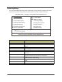
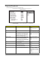
Entering Setup
Once enter Award BIOS CMOS Setup Utility, the Main Menu (as figure below) will appear on the screen.
Use arrow keys to select among the items and press <Enter> to accept or enter the sub-menu.
CMOS Setup Utility -- Copyright (C) 1985-2004, American Megatrends, Inc.
f Product Information
f Standard CMOS Setup
f Advanced BIOS Features
f Advanced Chipset Features
f Integrated Peripherals
f Power Management Setup
f PnP/PCI Configuration
f PC Health Status
f Frequency Control
Load Default Settings
Set Supervisor Password
Set User Password
Save & Exit Setup
Exit Without Saving
Enter : Select +/-/: Value F10: Save ESC: Exit
F9: Load Default Settings
mnlk : Move
F1: General Help
Standard CMOS setup for changing time, date, hard disk type, etc.
v02.56 (C)Copyright 1985-2004, American Megatrends, Inc.
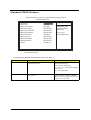
Parameter
Product Information
36
Description
This page shows the relevant information of the mainboard
Standard CMOS Features
This setup page includes all the items in standard compatible BIOS
Advanced BIOS Features
This setup page includes all the items of Award special enhanced
features
Integrated Peripherals
This setup page includes all onboard peripherals
Power Management Setup
This setup page includes all the items of Green function features
PnP/PCI Configuration
This setup page includes all configurations of PCI&PnP ISA resources
PC Health Status
This setup page is the System auto detect Temperature, voltage, fan
and speed
Load Default Settings
Default Settings indicates the value of the system parameters which
the system would be in best performance configuration
Set Supervisor Password
Change, set or disable password. It allows you to limit access to the
system and Setup, or just to Setup
Set User Password
Change, set or disable password. It allows you to limit access to the
system
Save & Exit Setup
Save CMOS value settings to CMOS and exit setup
Exit Without Saving
Abandon all CMOS value changes and exit setup
Chapter 2
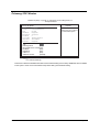
Product Information
CMOS Setup Utility - Copyright (C) 1985-2004, American Megatrends, Inc.
Product Information
Help Item
Product Name: Aspire T650/E500/AP F5
System S/N: 00000000
Main Board ID: ERC410M
Main Board S/N: 0000000
Asset Tag Number: Asset tag number: at least 2
System BIOS Version: R01-A3
SMBIOS Version: 2.3.1
System BIOS ID: R01-A3
BIOS Release Date: 06/16/05
: Move Enter : Select +/-/: Value F10: Save ESC: Exit
F9: Load Default Settings
mnlk
Parameter
Chapter 2
F1: General help
Description
Product Name
This item lists the product name
System S/N
This item lists the system serial number
Main Board ID
This item lists the mainboard ID
Main Board S/N
This item lists the mainboard serial number
Asset Tag Number
This item lists the asset tag number
System BIOS Version
This item lists the system BIOS version
SMBIOS Version
This item lists the system SMBIOS version
System BIOS ID
This item lists the system BIOS ID
BIOS Release Date
This item lists the BIOS release date
37
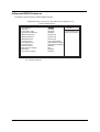
Standard CMOS Features
CMOS Setup Utility - Copyright (C) 1985-2004, American Megatrends, Inc.
Standard CMOS Setup
System Date
System Time
fPrimary IDE Master
[Tue 05/31/2005]
[19:55:59]
[Hard Disk]
fPrimary IDE Slave
fSecondary IDE Master
fSecondary IDE Slave
fThird IDE Master
fThird IDE Slave
fFourth IDE Master
fFourth IDE Slave
[Not Detected]
[Not Detected]
[Not Detected]
[Hard Disk]
Help Item
Use [ENTER], [TAB]
or [SHIFT-TAB] TO
select a field.
Use [+] or [-] to
configure system Time.
[Not Detected]
[Not Detected]
[Not Detected]
[1.44 MB31/2]
Floppy A
: Move Enter : Select +/-/: Value F10: Save ESC: Exit
F9: Load Default Settings
mnlk
F1: General help
The following table describes the parameters found in this menu:
Parameter
Date
Description
Lets you set the date following the weekdaymonth-day-year format
Options
Week : from Sun. to Sat., determined by
BIOS and is display only
Month : from Jan. through Dec.
Day : from 1 to 31 ( or the maximum allowed
in the month)
Year : from 1999 to 2098
Time
38
Lets you set the time following the hour-minutesecond format
The items format is <hour>
<minut><second>. The time is calculated
base on the 24-hour military-time clock. For
example, 1 p.m. is 13:00:00
Chapter 2
Parameter
IDE Primary/Secondary/
third/Fourth Master, Slave
Description
Allows you to configure the hard disk drive
connected to the master port of IDE channel. To
enter the IDE Master or Slave setup, press
[Enter]. The IDE CD-ROM is always
automatically detected.
Options
IDE HDD Auto-Detection Press [Enter] to
select this option for automatic device
detection.
IDE Primary/Secondary Master, Slave IDE
Device Setup. You can use one of three
methods:
Auto : Allows BIOS to automatically detect
IDE devices during POST (default)
None : Select this if no IDE devices are
used and the system will skip the automatic
detection step and allow for faster system
start up
Manual : User can manually input the
correct settings
Access Mode : Use this to set the access
mode for the hard drive. the four options are:
CHS/LBA/Large/Auto (default: Auto)
Floppy A
The category identifies the types of floppy disk
drive A that has been installed in the computer.
T
Cylinder : Number of
cylinders
T
Head : Number of
heads
T
Precomp : Write
precomp
T
Landing Zone : Landing
Zone
T
Sector : Number of
sectors
None : No floppy drive installed
360K, 5.25” : 5.25 inch PC type standard
drive ; 360Kbyte capacity
1.2M, 5.25” : 5.25 inch AT-type high-density
drive; 1.2M byte capacity (3.5 inch when 3
Mode is Enabled)
720K, 3.5” : 3.5 inch double-sided drive;
720Kbyte capacity
1.44M, 3.5” : 3.5 inch double-sided drive;
1.44Mbyte capacity
2.88M, 3.5” : 3.5 inch double-sided drive;
2.88Mbyte capacity
Chapter 2
39
Primary IDE Master
CMOS Setup Utility - Copyright (C) 1985-2004, American Megatrends, Inc.
Primary IDE Master
Primary IDE Master
Device
Vendor
Size
LBA Mode
Block Mode
PIO Mode
Async DMA
Ultra DMA
S.M.A.R.T.
: Hard Disk
: IC35L040AUVN07-0
: 41.1GB
: Supported
: 16 Sectors
:4
: MultiWord DMA-2
: Ultra DMA-2
: Supported
Help Item
Select the type of device
conneted to the system.
Type
[Auto]
LBA/Large Mode
[Auto]
Block (Multi-Sector Transfer[Auto]
PIO Mode
[Auto]
DMA Mode
[Auto]
S.M.A.R.T.
[Auto]
32Bit Data Transfer
[Enabled]
: Move Enter : Select +/-/: Value F10: Save ESC: Exit
F9: Load Default Settings
mnlk
F1: General help
This section indicate the detailed information and the related setting of the Primary IDE Master device installed
on the system. Users are recommended to keep these setting at their default setting.
40
Chapter 2
Advanced BIOS Features
The following screen shows the Advanced BIOS Features:
CMOS Setup Utility - Copyright (C) 1985-2004, American Megatrends, Inc.
Advanced BIOS Features
Virus Warning
Silent Boot
Confuguration Table
Quick Power On Self Test
fRemovable Drives
fHard Disk Drives
fCD/DVD Drives
First Boot Device
Second Boot Device
Third Boot Device
Boot Other Device
Boot Up NumLock Status
APIC Mode
CPU Hyper-Threading
[Disabled]
[Enabled]
[Disabled]
[Enabled]
[Press Enter]
Chapter 2
Enable/Disable Boot
Sector Virus Protection.
[Press Enter]
[Press Enter]
[1st FLOPPY DRIVE]
[HDD:PM-Maxtor 4R06]
[CD/DVD:SS-PIONEER]
[Enabled]
[On]
[Enabled]
[Enabled]
: Move Enter : Select +/-/: Value F10: Save ESC: Exit
F9: Load Default Settings
mnlk
Help Item
F1: General help
41
Parameter
Description
Options
This feature allows you to enable the VIRUS
warning function for IDE Hard Disk boot sector
protection. If this function is enabled and there
is someone attempt to write data into this area,
BIOS will show a warning message on screen
and the alarm will beep.
Enabled
Silent Boot
This features allows you to enable or disable if
the screen logo to display or no during POST
Enabled
Configuration Table
This feature allows you to enable or disable if
showing summary screen or not
Enabled
This feature allows the system to skip certain
tests while booting. When this function is
enabled, it will decrease the time needed to
boot the system, which means to quick power
on self test function
Enabled
First / Second / Third Boot
Device
The item allows you to set the sequence of boot
device where BIOS attempts to load the disk
operating system.
Floppy, LS120, Hard Disk, CD-ROM,
ZIP, USB-FDD, USB-ZIP, USBCDROM, USB-HDD, LAN, Disabled
Boot other Devices
This item allows you to enable or disable to boot
from other device
Enabled
Boot Up NumLock Status
This item allows you to enable or disable to set
keyboard is number keys or arrow keys
Enabled
APCI Mode
This option is used to set up enable or disable
the APCI funtion
Enabled
CPU Hyper-Threading
This item is only available when CPU and the
chipset support Hyper-Threading
Enabled : Enables CPU Hyper
Threading Feature. Please note that
this feature is only working for
operating system with multi processors
mode supported.
Virus Warning
Quick Power On Self Test
Disabled
Disabled
Disabled
Disabled
Disabled
Disabled
Disabled
Disabled : Disables CPU Hyper
Threading
42
Chapter 2
Advanced Chipset Features
This page sets up more advanced information about your system. Handle this page with caution. ANy changes
can affect the operation of your computer.
CMOS Setup Utility - Copyright (C) 1985-2004, American Megatrends, Inc.
Advanced Chipset Features
Boot Graphics Adapter Piori
UMA Frame Buffer Size
Help Item
[PEG/IGD]
[128MB]
Select which graphics controller to use as the primary
boot device.
: Move Enter : Select +/-/: Value F10: Save ESC: Exit
F9: Load Default Settings
mnlk
Parameter
Boot Graphics Adapter Piori
UMA Frame Buffer Size
Chapter 2
F1: General help
Description
Options
This item allow users to select which
graphics controller to use as the
primary boot device.
IGD
This item allows users to set the
UMA Frame Buffer Size manually
32, 64, 128, 256 MB
PEG/IGD
PCI/IGD
43
Integrated Peripherals
All onboard peripherals can be set up through this menu.
CMOS Setup Utility - Copyright (C) 1985-2004, American Megatrends, Inc.
Integrated Peripherals
USB 2.0 Support
USB Controller
USB Keyboard Support
USB Mouse Support
AC97 & Azalia LINK A
Onboard LAN function
Onboard LAN boot ROM
Onboard 1394 Controller
Serial Port1 Address
Serial Port2 Address
Parallel Port Address
Parallel Port Mode
ECP Mode DMA Channel
Parallel Port IRQ
[Enabled]
[Enabled]
[Enabled]
[Enabled]
[Enabled]
[Enabled]
[Disabled]
[Enabled]
[3F8/IRQ4]
[Disabled]
[378]
[ECP]
[DMA3]
[IRQ7]
Help Item
Options
Disabled
Enabled
: Move Enter : Select +/-/: Value F10: Save ESC: Exit
F9: Load Default Settings
mnlk
Parameter
USB 2.0 Controller
F1: General help
Description
Enable this item if the system supports USB 2.0
Options
Enabled : Enable USB 2.0
Controller
Disabled : Disable USB 2.0
Controller
USB Controller
This item is used to enable or disable the on-chip
USB
Enabled : Enable USB Controller
This item lets you enable or disable the USB
keyboard driver within the onboard BIOS. The
keyboard driver is simulates legacy keyboard
command and lets you use a USB keyboard
during POST or after boot if you do not have a
USB driver in the operating system
Enabled : Enable USB Keyboard
Support
This item lets you enable or disable the USB
mouse driver within the onboard BIOS. The
keyboard driver simulates legacy mouse
command and lets you use a USB mouse during
POST or after boot if you do not have a USB
driver in the operating system.
Enabled : Enable USB Mouse
Support
Onboard LAN function
This function is used to set whether the onboard
LAN card is enabled.
Enabled
Onboard LAN Boot ROM
This function decide whether to invoke the boot
ROM of the onboard LAN chip
Enabled
Onboard 1394 Controller
THis item allows users to enable or disable the
onboard 1394 Controller function.
Enabled
Serial Port 1/2 Address
This option is used to assign the I/O address and
interrupt request (IRQ) for onboard serial port 1
or 2
Auto : BIOS will automatically
setup the port 1 or 2 address
USB Keyboard Support
USB Mouse Support
Disabled : Disable USB Controller
Disabled : Disable USB Keyboard
Support
Disabled : Disable USB Mouse
Support
Disabled
Diabled
Disabled
3F8/IRQ4 (Serial Port 1 default)
2F8/IRQ3 (Serial Port 2 default)
3E8/IRQ4
2E8/IRQ3
Diabled : Disable onboard Serial
port 1 or 2
44
Chapter 2
Parameter
Paraller Port Address
Description
This item allows users to manually set the
address for Serial Port1&Port2
Options
278
378
3BC
Disabled
Parallel Port Mode
This item allows users to manually set the
Parallel Port Mode
ECP, EPP, Normal, EPP+ECP
ECP Mode DMA Channel
This item allows users to manually set the DMA
Channel for ECP value
DMA0
DMA1
DMA3
Paraller Port IRQ
Chapter 2
This item allows users to manually set the
Parallel Port IRQ value
IRQ5
IRQ7
45
Power Management Setup
The Power Management menu lets you configure your system to most effectively save energy while operating
in a manner consistent with your own style of computer use.
CMOS Setup Utility - Copyright (C) 1985-2004, American Megatrends, Inc.
Power Management Setup
ACPI function
ACPI Suspend Type
Hard Disk Power Down Mode
Soft-off by PWR-BTTN
PWRON After PWR-Fail
Power On by Ring
Wake-Up by PCI Card
USB KB Wake UP From S3
Resume by Alarm
[Enabled]
[S3 (STR)]
[Disabled]
[Delay 4 Sec]
[Last State]
[Disabled]
[Enabled]
[Enabled]
[Disabled]
Help Item
Enable / Disable
ACPI support for Operating
System.
Enable: If OS supports
ACPI.
Disable: If OS does not support ACPI.
: Move Enter : Select +/-/: Value F10: Save ESC: Exit
F9: Load Default Settings
mnlk
46
F1: General help
Chapter 2
Parameter
Description
Options
ACPI Function
This item allows you to enable or disable the ACPI
function
Enabled
ACPI Suspend Type
This item specifies the power saving modes for ACPI
function. S1(POS): The S1 sleep mode is a low power
state. In this state, no system context (CPU or chipset)
is lost and hardware maintains all system context. S3
(STR): The S3 sleep mode is s power-down state in
which power is supplied only to essential components
such as main memory and wake-capable devices and
all system context is saved to main memory. The
information stored in memory will be used to restore
the PC to the previous state when an wake-up event
occurs.
S1 (POS) : Set ACPI suspend
type to S1/POS(Power On
Suspend).
This setting controls how long a hard disk drive must
be left idle before ir spins down.
Disabled
HDD Power Down Mode
Disabled
S3 (STR) : Set ACPI suspend
type to S3/STR
Standby
Suspend
Soft-off by PWR-BTTN
This feature allows users to configure the power button
function.
Instand-off : Press down
button then power off instantly
Delay 4 Sec. : Press power
button 4 sec. to power off.
Enter suspend if button is
pressed less than 4 sec.
Under ACPI, you can create a software power down. If
the item is set to Instant-Off, then the power button
causes a software power down. If the item is set to
Delay 4 Sec, then you have to hole the power button
down for 4 seconds to cause a software power down.
Delay 4 Sec
An input signal on the serial Ring Indicator (RI) line (in
other words, an incoming call on the modem) awakens
the system from a soft off state.
Disabled : Disable Power On
by Ring function
Wake-Up by PCI Card
This option allows the activity of the PCI devices to
wake up the system from S3 sleep state.
Disabled
USB KB Wake Up From S3
This option allows the activity of the USB devices
to wake up the system from S3 sleep state.
Enabled
You can set “Resume by Alarm” item to enabled and
key in Data/Time to power on system
Disabled : Disable this
function
PWRON After PWR-BTTN
Power On by Ring
Resume by Alarm
On/Off
Enabled : Enable Power On
by Ring function
Enabled
Disabled
Enabled : Enable alarm
function to Power On system
If RTC Alarm Lead To Power
On is Enabled.
Date (of Month) Alarm :
Everyday, 1~31
Time (hh:mm:ss) Alarm:
(0.~23):(0~59):(0~59)
Chapter 2
47
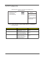
PnP/PCI Configuration
CMOS Setup Utility - Copyright (C) 1985-2004, American Megatrends, Inc.
PnP/PCI Configuration
Allocate IRQ to PCI VGA
PCI IDE BusMaster
PCI/VGA Palette Snoop
[Enabled]
[Enabled]
[Disabled]
Help Item
YES: Assign IRQ to PCI
VGA card if card requests
IRQ.
NO: Does not assign IRQ
to PCI VGA card even if card
requests an IRQ.
: Move Enter : Select +/-/: Value F10: Save ESC: Exit
F9: Load Default Settings
mnlk
Parameter
Allocate IRQ to PCI VGA
PCI IDE BusMaster
PCI/VGA Palette Snoop
48
F1: General help
Description
Options
This item allows users to enable or
disable the function of allocating
IRQ to PCI VGA
Enabled
THis item allows users to enable or
disable the PCI IDE BusMaster
function. Users are recommended to
keep this item at its default value.
Enabled
This option is only very rarely
needed. It should be left at
“Disabled” unless a video device
specifically requires the setting
enabled upon installation.
Disabled
Disabled
Disabled
Enabled
Chapter 2
PC Health Status
This section indicates the hardware information of the system including the CPU temperature, Ambient
Temperature, CPU FAN, and System FAN speed.
CMOS Setup Utility - Copyright (C) 1985-2004, American Megatrends, Inc.
PC Health Status
CPU Temperature
Ambient Temperature
:400C/1040F
:320C/890F
CPU FAN Speed
System FAN Speed
:3013 RPM
:N/A
Smart FAN Control
[Enabled]
Help Item
: Move Enter : Select +/-/: Value F10: Save ESC: Exit
F9: Load Default Settings
mnlk
F1: General help
The following table describes the parameters found in this menu:
Parameter
Description
Ambient Temperature
Delect ambient temperature automatically
CPU Temperature
Detect CPU Temperature automatically
CPU / SYSTEM FAN Speed (RPM)
Detect CPU/SYSTEM Fan Speed status automatically
Chapter 2
49
Frequency Control
This page helps you to set up the frequency control of the motherboard.
CMOS Setup Utility - Copyright (C) 1985-2004, American Megatrends, Inc.
Frequency Control
Ratio Status: Unlocked (Max: 16, Min:14)
Ratio Actual Value: 16
Auto Detect PCI Clk
[Enabled]
Spread Spectrum
[Enabled]
Help Item
Options
Disabled
Enabled
: Move Enter : Select +/-/: Value F10: Save ESC: Exit
F9: Load Default Settings
mnlk
Parameter
Ratio Status
F1: General help
Description
You can only adjust the Ratio CMOS if you installed an unlocked CPU.
Ratio Actual Value
This item indicates the ratio actual value of this motherboard
Auto Detect PCI Clk
When this item is enabled, BIOS will disable the clock signal of free PCI slots
Spread Spectrum
If you enable spread spectrum, ite can significantly reduce the EMI(ElectroMagnetic Interference) generated by the system.
50
Chapter 2
Load Default Settings
Selecting the field loads the factory defaults for BIOS and Chipset Features which the system automatically.
detects. THis option opens a dialog box that lets you install optimized defaults for all appropriate items in the
Setup Utility. Press <OK> and then <Enter> to install the defaults. Press <Cancel> and then <Enter> to not
install the defaults.
If you only want to install setup dafaults for a specific option, select and display that option, and then
press<F9>.
Chapter 2
51
Set Supervisor/User Password
When this function is selected, the following message appears at the center of the screen to assist you in
creating a password.
ENTER PASSWORD
Type the password, up to eight characters, and press<Enter>. The password typed now will clear any
previously entered password from CMOS memory. You will be asked to confirm the password. Type the
password again and press ,Enter>. You may also press <Esc> to abort the selection.
To disable password, just press <Enter> when you are prompted to enter password. A message will confirm
the password being disabled. Once the password is disabled, the system will boot and you can enter BIOS
Setup freely.
PASSWORD DISABLED
If you have selected “System” in “Security Option” of “BIOS Features Setup” menu, you will be promped for the
password every time the system reboots or any time you try to enter BIOS Setup.
If you have selected “Setup” at “Security Option” from “BIOS Features Setup” menu, you will be prompted for
the password only when you enter BIOS Setup.
Supervisor Password has higher priority than User Password. You can use Supervisor Password when
booting the system or entering BIOS Setup to modify all settings. Also you system or entering BIOS Setup but
can not modify any setting if Supervisor Password is enabled.
52
Chapter 2
Save & Exit Setup
Highlight this item and press <Enter> to save the changes that you have made in the Setup Utility and exit the
Setup Utility.
When the Save and Exit dialog box appears, press <Y> to save and exit, or press <N> to return to the main
menu.
Chapter 2
53
Exit Without Saving
Highlight this item and press <Enter> to discard any changes that you have made in the Setup Utility and exit
the Setup Utility.
When the Exit Without Saving dialog box appears, press <Y> to discard changes and exit, or press <N> to
return to the main menu.
NOTE: If you have made settings that you do not want to save, use the "Exit Without Saving" item and press
<Y> to discard any changes you have made.
54
Chapter 2
Chapter 3
Machine Disassembly and Replacement
To disassemble the computer, you need the following tools:
T
Wrist grounding strap and conductive mat for preventing electrostatic discharge.
T
Wire cutter.
T
Phillips screwdriver (may require different size).
NOTE: The screws for the different components vary in size. During the disassembly process, group the
screws with the corresponding components to avoid mismatches when putting back the components.
Chapter 3
55
General Information
Before proceeding with the disassenbly procedure, make sure that you do the following:
56
1.
Turn off the power to the system and all peripherals.
2.
Unplug the AC adapter and all power and signal cables from the system.
Chapter 3
Disassembly Procedure
This section tells you how to disassemble the system when you need to perform system service. Please also
refer to the disassembly video, if available.
CAUTION: Before you proceed, make sure you have turned off the system and all peripherals connected to it.
Chapter 3
57
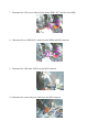
Aspire T650 Standard Disassembly Procedure
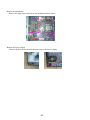
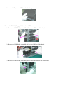
Opening the System
1. Place the system unit on a flat, steady surface.
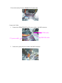
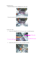
2. Turn the housing down, slide the Lock-handle as shown , meanwhile slide the left side door out .
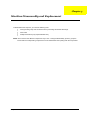
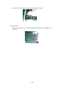
Remove the ADD ON Cards
1. Release the PCI-Lock as shown bellow, then remove it.
2. Release the VGA-slot Lock shown bellow, then pull out the VGA Card.
58
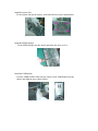
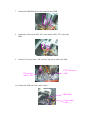
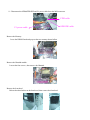
3. Remove the TV Tuner Card.
4. Remove the Modem card.
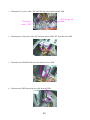
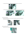
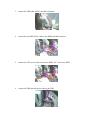
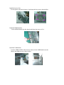
Remove the Cables
1. Disconnect the SPDIF and AUDIO cables.
AUDIO Cable
SPDIF Cable
2. Disconnect the USB and Card-reader Cables.
USB Cable
Card-reader
Cable
58
59
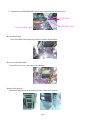
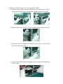
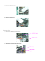
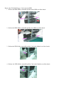
3. Disconnect 12V power cable “ PD” and CPU fan power cable from the M/B.
CPU fan power
cable
12V power
cable “ PD”
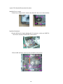
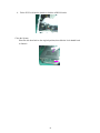
4. Disconnect the 4 Pin power cable “PE” from the master ODD, “PF” from the slave ODD.
5. Disconnect the ODD IDE cable from the master & slave ODD.
6. Disconnect the FDD data and power cable from the FDD.
60
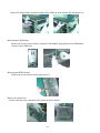
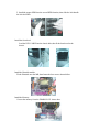
7. Disconnect the “PB” power cable from the master HDD, “PC” from the slave HDD.
8. Disconnect the two HDD SATA cables from the HDDs and M/B connector.
9. Disconnect the LED cable ASSY from the M/B Connector.
10. Disconnect the system fan power cable from the M/B Connector.
61
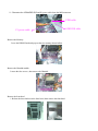
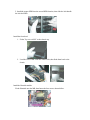
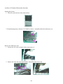
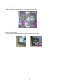
11. Disconnect the ODD&FDD IDE and P1 power cable from the M/B connector.
FDD cable
ODD IDE cable
P1 power cable
Remove the Memory
Loose the DIMM Latch and pop out the two memory shown bellow.
Remove the Heatsink module.
Loosen the four screws , then remove the Heatsink.
Remove the front bezel
Release the three latches on the front bezel, then remove the front bezel.
62
Remove the CD-ROM, Floppy, Card-reader and HDD
1. Release the HDD-Holder, meanwhile pull the master HDD out of the chassis.
2. Release the HDD-Holder, meanwhile pull the slave HDD out of the chassis.
3. Release the FDD-Holder, meanwhile pull the Card-reader Module out of the chassis.
4. Release the FDD-Holder, meanwhile pull the Card-reader Module out of the chassis.
63
Release the ODD-Holder, meanwhile pull the Slave ODD out of the chassis, then the Master one.
Removing the USB Module
Remove the screw as shown bellow, detach the USB Module, then pull down the USB&Audio
cable from the USB board.
Removing the SPDIF Module
Remove the screw as shown bellow and remove it.
Remove the System Fan
Remove the four screws and remove the system fan shown bellow.
64
Remove the Mainboard
Remove the eight screws and remove the Mainboard shown bellow.
Remove the Power-supply
Remove the four screws shown bellow and remove the Power-supply.
65
Aspire T650 Standard Reassembly Procedure
Install the Power-supply
Fit the Power-supply into the chassis, then fasten the four screws shown bellow.
Install the Mainboard
1.Put the M/B into the chassis aligning the I/O connector , make sure M/B VIA
hole fits the oriented STAND OFF on the chassis.
2.Fix the M/B with 8pcs screws by turn of number in the picture.
1
5
4
6
7
3
66
8
2
Install the System Fan
Fit the System Fan into the chassis , then fasten the four screws shown bellow.
Install the SPDIF Module
Fit the SPDIF Module into the chassis and fasten the screw to fix it.
Install the USB Module
Lead the USB&AUDIO cables into the chassis, fit the USB Module onto the
chassis, then tight the screw shown bellow.
Install the CD-ROM, Floppy, Card-reader Module and HDD
1.Install the master ODD into the first ODD location, then install the slave ODD
into the second ODD location, and slide the lock handle the lock the ODDs.
2.Install the FDD into the first 3.25” location, and slide the lock handle the lock it.
3. Install the Card-reader Module (with cable) into the second 3.25” location, and
slide the lock handle the lock it.
4. Install the slave HDD into the forth HDD location, then slide the lock handle the
lock the HDD.
5. Install the master HDD into the second HDD location, then slide the lock handle
the lock the HDD.
Install the front bezel
Lead the LED CABLE into the chassis hole, then fit the front bezel to the
chassis.
Install the Heatsink module.
Fit the Heatsink onto the MB, then fasten the four screws shown bellow.
Install the Memory
1.Insert the memory1 into the DIMM SLOT1 shown here.
2.Insert the memory2 into the DIMM SLOT2 shown here.
Connect the Cables
1. Connect the ODD&FDD IDE and P1 power cable to the M/B connector.
FDD cable
P1 power cable
ODD IDE cable
2. Connect the system fan power cable to the M/B Connector.
3. Connect the LED cable ASSY to the M/B Connector.
4. Connect the two HDD SATA cables to the HDDs and M/B connector.
5. Connect the “PB” power cable to the master HDD, “PC” to the slave HDD.
6. Connect the FDD data and power cable to the FDD.
7. Connect the ODD IDE cable to the master & slave ODD.
8. Connect the 4 Pin power cable “PE” to the master ODD, “PF” to the slave
ODD.
9. Connect 12V power cable “ PD” and CPU fan power cable to the M/B.
12V power
cable “ PD”
CPU fan power
cable
10. Connect the USB and Card-reader Cables.
USB Cable
Card-reader
Cable
11. Connect the SPDIF and AUDIO cables.
AUDIO Cable
SPDIF Cable
Install the ADD ON Cards
1. Insert the Modem Card into the PCI SLOT3.
2. Insert the TV Tuner Card into the PCI SLOT2.
3. Insert the VGA Card into the PCI-E slot, then rail the latch on to hold it.
4. Fit the PCI-Lock into the chassis to lock the ADD ON cards.
Close the System
Place the side door back to the original position, then slide the Lock-handle back
to fasten it.
74
Aspire E500 Standard Disassembly Procedure
Opening the System
1. Place the system unit on a flat, steady surface.
2. Turn the housing down, slide the Lock-handle as shown , meanwhile slide the left side door out .
Remove the ADD ON Cards
1. Release the PCI-Lock as shown bellow, then remove it.
2. Release the VGA-slot Lock shown bellow, then pull out the VGA Card.
75
3. Remove the TV Tuner Card.
4. Remove the Modem card.
Remove the Cables
1. Disconnect the SPDIF and AUDIO cables.
AUDIO Cable
SPDIF Cable
2. Disconnect the USB and Card-reader Cables.
USB Cable
Card-reader
Cable
3. Disconnect 12V power cable “ PD” and CPU fan power cable from the M/B.
12V power
cable “ PD”
CPU fan power
cable
4. Disconnect the 4 Pin power cable “PE” from the master ODD, “PF” from the slave ODD.
5. Disconnect the ODD IDE cable from the master & slave ODD.
6. Disconnect the FDD data and power cable from the FDD.
7. Disconnect the “PB” power cable from the master HDD, “PC” from the slave HDD.
8. Disconnect the two HDD SATA cables from the HDDs and M/B connector.
9. Disconnect the LED cable ASSY from the M/B Connector.
10. Disconnect the system fan power cable from the M/B Connector.
11. Disconnect the ODD&FDD IDE and P1 power cable from the M/B connector.
FDD cable
P1 power cable
Remove the Memory
Loose the DIMM Latch and pop out the two memory shown bellow.
Remove the Heatsink module.
Loosen the four screws , then remove the Heatsink.
Remove the front bezel
1. Release the three latches on the front bezel, then remove the front bezel.
ODD IDE cable
2. Remove the Top-cover ASSY form the chassis top.
Remove the CD-ROM, Floppy, Card-reader and HDD
1. Release the HDD-Holder, meanwhile pull the master HDD out of the chassis.
2. Release the HDD-Holder, meanwhile pull the slave HDD out of the chassis.
3. Release the FDD-Holder, meanwhile pull the Card-reader Module out of the chassis.
4. Release the FDD-Holder, meanwhile pull the Card-reader Module out of the chassis.
5. Release the ODD-Holder, meanwhile pull the Slave ODD out of the chassis, then the Master one.
Removing the USB Module
Remove the screw as shown bellow, detach the USB Module, then pull down the USB&Audio
cable from the USB board.
Removing the SPDIF Module
Remove the screw as shown bellow and remove it.
Remove the System Fan
Remove the four screws and remove the system fan shown bellow.
Remove the Mainboard
Remove the eight screws and remove the Mainboard shown bellow.
Remove the Power-supply
Remove the four screws shown bellow and remove the Power-supply.
82
Aspire E500 Standard Reassembly Procedure
Install the Power-supply
Fit the Power-supply into the chassis, then fasten the four screws shown bellow.
Install the Mainboard
1.Put the M/B into the chassis aligning the I/O connector , make sure M/B VIA
hole fits the oriented STAND OFF on the chassis.
2.Fix the M/B with 8pcs screws by turn of number in the picture.
1
5
4
6
7
3
83
8
2
Install the System Fan
Fit the System Fan into the chassis , then fasten the four screws shown bellow.
Install the SPDIF Module
Fit the SPDIF Module into the chassis and fasten the screw to fix it.
Install the USB Module
Lead the USB&AUDIO cables into the chassis, fit the USB Module onto the
chassis, then tight the screw shown bellow.
Install the CD-ROM, Floppy, Card-reader Module and HDD
1.Install the master ODD into the first ODD location, then install the slave ODD
into the second ODD location, and slide the lock handle the lock the ODDs.
2.Install the FDD into the first 3.25” location, and slide the lock handle the lock it.
3. Install the Card-reader Module (with cable) into the second 3.25” location, and
slide the lock handle the lock it.
4. Install the slave HDD into the forth HDD location, then slide the lock handle the
lock the HDD.
5. Install the master HDD into the second HDD location, then slide the lock handle
the lock the HDD.
Install the front bezel
1. Fit the Top-cover ASSY to the chassis top.
2. Lead the LED CABLE into the chassis hole, then fit the front bezel to the
chassis.
Install the Heatsink module.
Fit the Heatsink onto the MB, then fasten the four screws shown bellow.
Install the Memory
1.Insert the memory1 into the DIMM SLOT1 shown here.
2.Insert the memory2 into the DIMM SLOT2 shown here.
Connect the Cables
1. Connect the ODD&FDD IDE and P1 power cable to the M/B connector.
FDD cable
P1 power cable
ODD IDE cable
2. Connect the system fan power cable to the M/B Connector.
3. Connect the LED cable ASSY to the M/B Connector.
4. Connect the two HDD SATA cables to the HDDs and M/B connector.
5. Connect the “PB” power cable to the master HDD, “PC” to the slave HDD.
6. Connect the FDD data and power cable to the FDD.
7. Connect the ODD IDE cable to the master & slave ODD.
8. Connect the 4 Pin power cable “PE” to the master ODD, “PF” to the slave
ODD.
9. Connect 12V power cable “ PD” and CPU fan power cable to the M/B.
12V power
cable “ PD”
CPU fan power
cable
10. Connect the USB and Card-reader Cables.
USB Cable
Card-reader
Cable
11. Connect the SPDIF and AUDIO cables.
AUDIO Cable
SPDIF Cable
Install the ADD ON Cards
1. Insert the Modem Card into the PCI SLOT3.
2. Insert the TV Tuner Card into the PCI SLOT2.
3. Insert the VGA Card into the PCI-E slot, then rail the latch on to hold it.
4. Fit the PCI-Lock into the chassis to lock the ADD ON cards.
Close the System
Place the side door back to the original position, then slide the Lock-handle back
to fasten it.
91
AcerPower F5 Standard Disassembly Procedure
Opening the System
1. Place the system unit on a flat, steady surface.
2. Turn the housing down, slide the Lock-handle as shown , meanwhile slide the left side door out .
Remove the ADD ON Cards
1. Release the PCI-Lock as shown bellow, then remove it.
2. Release the VGA-slot Lock shown bellow, then pull out the VGA Card.
92
3. Remove the TV Tuner Card.
4. Remove the Modem card.
Remove the Cables
1. Disconnect the SPDIF and AUDIO cables.
AUDIO Cable
SPDIF Cable
2. Disconnect the USB and Card-reader Cables.
USB Cable
Card-reader
Cable
3. Disconnect 12V power cable “ PD” and CPU fan power cable from the M/B.
12V power
cable “ PD”
CPU fan power
cable
4. Disconnect the 4 Pin power cable “PE” from the master ODD, “PF” from the slave ODD.
5. Disconnect the ODD IDE cable from the master & slave ODD.
6. Disconnect the FDD data and power cable from the FDD.
7. Disconnect the “PB” power cable from the master HDD, “PC” from the slave HDD.
8. Disconnect the two HDD SATA cables from the HDDs and M/B connector.
9. Disconnect the LED cable ASSY from the M/B Connector.
10. Disconnect the system fan power cable from the M/B Connector.
11. Disconnect the ODD&FDD IDE and P1 power cable from the M/B connector.
FDD cable
P1 power cable
Remove the Memory
Loose the DIMM Latch and pop out the two memory shown bellow.
Remove the Heatsink module.
Loosen the four screws , then remove the Heatsink.
Remove the front bezel
Release the three latches on the front bezel, then remove the front bezel.
ODD IDE cable
Remove the CD-ROM, Floppy, Card-reader and HDD
1. Release the HDD-Holder, meanwhile pull the master HDD out of the chassis.
2. Release the HDD-Holder, meanwhile pull the slave HDD out of the chassis.
3. Release the FDD-Holder, meanwhile pull the Card-reader Module out of the chassis.
4. Release the FDD-Holder, meanwhile pull the Card-reader Module out of the chassis.
Release the ODD-Holder, meanwhile pull the Slave ODD out of the chassis, then the Master one.
Removing the USB Module
Remove the screw as shown bellow, detach the USB Module, then pull down the USB&Audio
cable from the USB board.
Removing the SPDIF Module
Remove the screw as shown bellow and remove it.
Remove the System Fan
Remove the four screws and remove the system fan shown bellow.
Remove the Mainboard
Remove the eight screws and remove the Mainboard shown bellow.
Remove the Power-supply
Remove the four screws shown bellow and remove the Power-supply.
99
AcerPower F5 Standard Reassembly Procedure
Install the Power-supply
Fit the Power-supply into the chassis, then fasten the four screws shown bellow.
Install the Mainboard
1.Put the M/B into the chassis aligning the I/O connector , make sure M/B VIA
hole fits the oriented STAND OFF on the chassis.
2.Fix the M/B with 8pcs screws by turn of number in the picture.
1
5
4
6
7
3
100
8
2
Install the System Fan
Fit the System Fan into the chassis , then fasten the four screws shown bellow.
Install the SPDIF Module
Fit the SPDIF Module into the chassis and fasten the screw to fix it.
Install the USB Module
Lead the USB&AUDIO cables into the chassis, fit the USB Module onto the
chassis, then tight the screw shown bellow.
Install the CD-ROM, Floppy, Card-reader Module and HDD
1.Install the master ODD into the first ODD location, then install the slave ODD
into the second ODD location, and slide the lock handle the lock the ODDs.
2.Install the FDD into the first 3.25” location, and slide the lock handle the lock it.
3. Install the Card-reader Module (with cable) into the second 3.25” location, and
slide the lock handle the lock it.
4. Install the slave HDD into the forth HDD location, then slide the lock handle the
lock the HDD.
5. Install the master HDD into the second HDD location, then slide the lock handle
the lock the HDD.
Install the front bezel
Lead the LED CABLE into the chassis hole, then fit the front bezel to the
chassis.
Install the Heatsink module.
Fit the Heatsink onto the MB, then fasten the four screws shown bellow.
Install the Memory
1.Insert the memory1 into the DIMM SLOT1 shown here.
2.Insert the memory2 into the DIMM SLOT2 shown here.
Connect the Cables
1. Connect the ODD&FDD IDE and P1 power cable to the M/B connector.
FDD cable
P1 power cable
ODD IDE cable
2. Connect the system fan power cable to the M/B Connector.
3. Connect the LED cable ASSY to the M/B Connector.
4. Connect the two HDD SATA cables to the HDDs and M/B connector.
5. Connect the “PB” power cable to the master HDD, “PC” to the slave HDD.
6. Connect the FDD data and power cable to the FDD.
7. Connect the ODD IDE cable to the master & slave ODD.
8. Connect the 4 Pin power cable “PE” to the master ODD, “PF” to the slave
ODD.
9. Connect 12V power cable “ PD” and CPU fan power cable to the M/B.
12V power
cable “ PD”
CPU fan power
cable
10. Connect the USB and Card-reader Cables.
USB Cable
Card-reader
Cable
11. Connect the SPDIF and AUDIO cables.
AUDIO Cable
SPDIF Cable
Install the ADD ON Cards
1. Insert the Modem Card into the PCI SLOT3.
2. Insert the TV Tuner Card into the PCI SLOT2.
3. Insert the VGA Card into the PCI-E slot, then rail the latch on to hold it.
4. Fit the PCI-Lock into the chassis to lock the ADD ON cards.
Close the System
Place the side door back to the original position, then slide the Lock-handle back
to fasten it.
108
Chapter 4
FRU (Field Replaceable Unit) List
This chapter gives you the FRU (Field Replaceable Unit) listing in global configurations of Aspire T650/E500
and AcerPower F5. Refer to this chapter whenever ordering for parts to repair or for RMA (Return
Merchandise Authorization).
IMPORTANT: Please note WHEN ORDERING FRU PARTS, that you should check the most up-to-date
information available on your regional web or channel. For whatever reasons a part number
change is made, it will not be noted in the printed Service Guide. For ACER-AUTHORIZED
SERVICE PROVIDERS, your Acer office may have a DIFFERENT part number code to those
given in the FRU list of this printed Service Guide. You MUST use the local FRU list provided by
your regional Acer office to order FRU parts for repair and service of customer machines.
IMPORTANT: Please note that Acer Corporation sells only the parts listed in the following table. Please
be reminded that though some parts are disassembled in Chapter 3 for demonstration
purpose, Acer Corporation does not provide these parts.
NOTE: To scrap or to return the defective parts, you should follow the local government ordinance or
regulations on how best to dispose it, or follow the rules set by your regional Acer office on how to
return it.You can access to the website for the latest Parts version http://aicsl.acer.com.tw/spl/
Chapter 4
109
Aspire E500/T650 Exploded Diagram
Item
110
Description
3
OPTICAL DRIVE
4
FDD WITH PANEL
5
FLOPPY DISK DRIVE
6
MOTHER BOARD
7
HDD LOCK SLIDE
8
FDD LOCK SLIDE
9
CDROM LOCK SLIDE
10
USB BOARD
11
USB BKT
12
RIGHT COVER
13
CHASSIS
14
POWER SUPPLY
15
FAN
Chapter 4
Item
Chapter 4
Description
16
PCI BKT
17
LEFT COVER
111
AcerPower F5 Exploded Diagram
Item
112
Description
1
3.5” COVER
2
5.25” COVER
3
FRONT BEZEL
4
OPTICAL DRIVE
5
FDD WITH PANEL
6
FLOPPY DISK DRIVE
7
MOTHER BOARD
8
HDD LOCK SLIDE
9
FDD LOCK SLIDE
10
CDROM LOCK SLIDE
11
USB BOARD
12
USB BKT
13
RIGHT COVER
14
CHASSIS
15
POWER SUPPLY
16
FAN
17
PCI BKT
18
LEFT COVER
Chapter 4