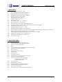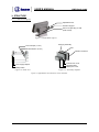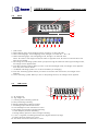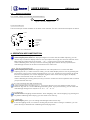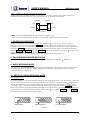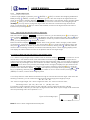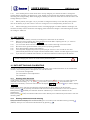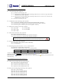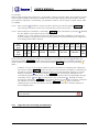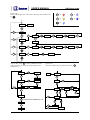
1
USER’S MANUAL
Bench scale
CWP
USER’S MANUAL
CWP. Bench scale
CONTENTS
1. Main data
3
2. Main features
3
3. Structure
4
4. Operation keys instruction
6
5. Digit input
7
6. RS-232 output and printing
7
7. Power-on operation
9
8. Two weighing modes switching
9
9. Basic weighing mode
9
10. Setup in check weighing mode
9
11. Display in check weighing mode
11
12. Backlight selecting
12
13. Auto rectifying
12
14. Storage battery maintaining
12
15. Use guide
13
16. Data setting and calibrating
13
Disclaimer
We’ve been tried to provide complete and accurate information in this manual, however,
we make no representations and warranties with respect to the contents of this manual,
and reserve the right to make change to our products and manual without notice.
2
USER’S MANUAL
CWP. Bench scale
1. MAIN DATA
1.1
1.2
1.3
1.4
1.5
1.6
1.7
1.8
1.9
1.10
1.11
1.12
1.13
1.14
1.15
1.16
1.17
1.18
1.19
1.20
Signal input range: 0mV ~ 8mV
Zero point temperature drift ≤ 0.15μV/ºC
Sensitivity temperature drift ≤ 10 ppm/ºC
A/D conversion resolution ration: 500000
Display resolution ration: 30000
A/D conversion rate: 168T/S
Display update rate: 10T/S
Accuracy class: 3
Min. Display value: 1/ 2/ 5 available
Non-linearity error: ≤ 0.01%F·S.
Baud rate: 600, 1200, 2400, 4800, 9600 (option)
Load cell excitation voltage: DC5V, drives up to 4 load cells of 350Ω.
Operation temperature: 0 ~ 40 ºC
Storage temperature: -25ºC ~ 55ºC
Relative humidity: ≤ 90% (no condensation)
Power supply: DC 6V5Ah, free-maintenance storage battery and power adaptor of 9V, 500 mA.
Working time of storage battery power: ≥ 100 hours
(Fully charged, backlight off and drives only 1 load cell of 350Ω)
Display style: 6-digit 1-inch 7-segment LCD.
Dimensions: 300x350 mm, 500x400 mm.
Peso neto: ≤ 3 Kg
2. MAIN FEATURES
2.1
2.2
2.3
2.4
2.5
2.6
2.7
2.8
2.9
2.10
2.11
2.12
2.13
2.14
2.15
2.16
2.17
2.18
2.19
2.20
Indicator enclosure: all stainless steel
Indicator display angle adjustable (≥ 90º)
Mount style: table and wall
IP66
Two operation modes: weighing and check weighing
Complete keyboard calibration
Auto rectifying
Zero position auto tracking
Digit filtering
Full range tare
Overload indicating
Three-point (over, accept, under) indicating
Target-value weight weighing
Two setup modes of check weighing
a. Weight value input mode
b. Percentage mode
Unit conversion
RS-232 output (option)
Charge and battery voltage indicating
LED backlight and lighting mode set
Auto shut-off selecting
Printing function under normal weighing state
3
USER’S MANUAL
CWP. Bench scale
3. STRUCTURE
3.1
Structure diagram
Adjustable knob
Indicator support
Hole for suspending on wall
(total 3 holes)
Figure 1-a: Adjustable support
Seal ring assembly
Load cell input (7-core)
PCB
RS.232 Interface (5-core)
Indicator enclosure
Indicator rear cover
Power supply adaptor
Battery switch
Figure 1-b: Rear view
Storage battery
Battery box cover
Figure 1-c: Assembly diagram
Figure 1: Appearance and structure of the indicator
4
USER’S MANUAL
3.2
CWP. Bench scale
Panel
1
2
3
>
Auto Off
lb
kg
pc
Print
=
<
8
AC
~
NTG
9
Auto BL
4
Over
Accept
Under
0
5
6
7
%
CHARGE
BL
C
I/O
POWER
VII
%
VI
MODE UNITS
EXIT
SET
V
IV
0
T
ENTER
III
II
I
1. LCD screen
2. Red indication light: check weighing mode, the light is on when WX ≥ WH
3. Green indicating light: check weighing mode, the light is on when WH > WX > WL
4. Yellow indicationg light: check weighing mode, the light is on when WX ≤ WL
*Note : WX refers to the weight of load; WH refers to high limit value; WL refers to low limit value. See
item 10.3 for details.
5. Percentage unit indicating symbol: when you input the high and low limit value by percentage mode,
the triangle cursor appears here.
6. “Auto BL” indicating symbol: When you turn on the auto backlight mode, the tiangle cursor appears
here. See item 12.3 for details.
7. “CHARGE” indicating symbol: it is on when the battery is recharging
8. “Auto Off” indicating symbol: When you switch on the auto shut-off function, the triangle cursor
appears.
9. “Print” indicating symbol: When you turn on the printing function, the triangle cursor appears.
3.3
LCD screen
M
L
K
lb
kg
pc
AC
NTG
A. “lb” weight unit
Auto BL
B. “Kg” weight unit
J
I
H
G
C. Counting state indicating (optional)
D. Zero positioning indicating
E. Weight stabilization indicating symbol
F. Percentage input switched-on cursor
G. Auto-backlight function switched-on cursor
H. Net weight, tare and gross weight indicating
I. Power adaptor power-on indicating
J. Storage battery power-on and its voltage indicating
K. 1-inch, 7-segment (containing decimal point) digital character (6-digit)
L. Printing function switched on cursor
M. Auto shuft-off function switched-on cursor
~
0
E
D
A
B
C
%
F
5
USER’S MANUAL
3.4
CWP. Bench scale
Electrical connection
3.4.1 Power supply is provide with standard adaptor.
-
+
Figure 4-a: Power adaptor unit
3.4.2 Load cell input
The load cell input socket installed on the back of the indicator. The wire connection description as follow:
SHIELD
5
6
4
-SIG
3
+SIG
7
1
2
+EXC -EXC
1
2
3
4
5
+ Excitation
- Excitation
+Signal
- Signal
Shield
Figure 4-b: Connection
4. OPERATION KEYS INSTRUCTION
0
T
ENTER
I. Zero and place-shifting key
Under weighing state, when the displayed weight is not more than 2% of Max Capacity, you can
use this key to make the display return to zero (the repeat zero range can’t be more than 4% of the
Max Capacity). When this key is pressed, “ → 0 ← ” cursor on the LCD screen will appear.
Under calibrating state, this key is used for selecting digit place. When this key is pressed, the
selected digit will move to the left one and flash at the same time.
II. Tare and confirmation key
Under weighing state, when the weight loaded on the scale platform is not more than Max.
Capacity plus 9e (”e” refers to division value), you can make display return to zero by pressing this
key, and the cursor on the screen will change from “G” to “N”. At this time if tou remove the goods
from the scale platform, the screen displays a negative value. Press this key again, the display
returns to zero and the cursor “N” returns to “G”.
Under calibrating and setting states, this key is used to confirm the current operation and to remind
you proceed the next step.
III. Unit converting and digit increment key
UNITS Under weighing state according to F1.1, if you press this key once, the weight unit will convert
between “kg” and “lb”. Under calibrating and setting state, if you press this key, you can make the
selected digit change in the sequence of “0 → 1 → 2 ... 9 → 0”.
IV. Mode key
MODE You can convert weighing modes between “basic weighing” and “check weighing” by pressing this
key. While calibrating and rectifying, you also need to use this key.
SET
BL
V. Clear key
C Under weighing state, you can change the backlight status via this key.
EXIT
In check weighing mode, it si used for clearing the previous value in storage. In addition, you can
press this key to withdraw from calibrating and rectifying states.
6
USER’S MANUAL
%
CWP. Bench scale
VI. Printing and value difference key.
1. In check weighing mode, you can press this key to change the displayed content and make
the display convert between value difference and normal value.
While setting the high and low limit under check weighing state, you can select percentage
setup mode via this key, and at the same time the triangle cursor of “%” indicating symbol will
appear.
2. Under weighing state when F1.5=0, the indicator will output serial printing signal after
pressing this key.
VII. I/O key.
I/O This key is used for turning on or turning off power supply, and it has other functions while
POWER
calibrating.
5. DIGIT INPUT
While processing the operation of item 10.3, 10.4 in this manual or calibrating, you need to input the digit.
The digit input is all fulfilled via UNITS and 0
in cooperating. 0
refers to place-shifting key, it is used
for selecting digit place and the selected digit place will flash. At this time if you press UNITS , the selected
falshing digit will change in “0 → 1 → 2 ... 9 → 0”.
For example: to input a group of digit 2345.
Step 1: Press C (C), the indicator display
* Note: While inputing the digit, first press C (C) to make the indicator display
and then
input the digit. It is possible that “X” refers to “ ”, “H”, “L” or “E” indicating symbol. And “0” refers
to the flashing place.
Step 2: Press UNITS 5 times,
is displayed
Step 3: Press 0
one,
is displayed
Step 4: Press UNITS 4 times,
is displayed
Step 5: Press 0
one,
is displayed
Step 6: Press UNITS 3 times,
is displayed
Step 7: Press 0
once,
is displayed
Step 8: Press UNITS twice,
is displayed
Step 9: Press T (ENTER) to confirm and enter the next step.
* Note: Under some special states, you may press [EXIT] to withdraw.
Thus a group of digit input is finished.
BL
EXIT
BL
EXIT
ENTER
6. OUTPUT AND PRINTING RS-232
6.1
Serial output.
6.1.1 The 5-core metal socket (figure 5) is used for Rs232 hardware interface, the socket is mounted
on back of the indicator.
4
5
3
1
2
TXD
GND
Figure 5: interface of serial signal output
7
USER’S MANUAL
CWP. Bench scale
6.1.2
The serial data (ASCII code) is transmitted in continuous mode by MCS-51 way 1. Every group
of data has 17 frames including 1 frame of start character (02), 3 frames of state mark, 6 frames of data
displaying, 6 frames of tare data and 1 frame of enter, as follows:
STX
State A
State B
State C
Displayed value
Tare value
Enter
STX: start character, 02H
State A: Control character for decimal point ( D7 refers to verification bit)
Verification
bit
D7
D6
D5
D4
D3
D2
D1
D0
Decimal point place
0
0
0
0
0
1
1
1
1
1
0
0
0
0
0
1
1
1
1
1
0
0
1
1
1
1
1
0
0
1
0
1
0
1
0
Without decimal point
1-digit decimal
2-digit decimal
3-digit decimal
4-digit decimal
State B: comprehensive control character.
D7 verification bit
D6 0
D5 1
D4 1
D3 Dynamic mark bit
D3=0, stability;
D2 Overload mark bit
D2=0, normality;
D1 Positive and negative mark bit
D1=0, positive number;
D0 Gross weight and net weight mark bit
D0=0, gross weight;
0.0
0.00
0.000
0.0000
D3=1, non-stability (dynamic)
D2=1, overload
D1=1, negative number
D0=1, net weight
State C: output space character
6.1.3 Every frame consists of 10 digits. The first is start bit, “0”. The ninth is stop bit, “1”.
One of the other eight is correction bit and the other seven are all data bits (from low to high), the format
is as follows
Start bit
D0
D0
D0
D0
D0
D0
D0
D0
Stop bit
Verification bit
Figure 6: Frame format
6.2
Ticket printing output
6.2.1
Option of the indicator data
This indicator can be matched to EPSON TM-U295 micro-printer. In order to match to the printer, set
F1.5=0, and set F1.3 consistent to the printer. At this moment, if you press [P] key, the printer will print
the ticket as the following format:
No. 03
G=1.576 lb
T= 0.948 lb
N= 0.628 lb
When the weight unit is lb.
No. 04
G=0.714 kg
T= 0.429 kg
N= 0.285 kg
When the weight unit is kg.
Figure 7: Ticket printing format
8
USER’S MANUAL
CWP. Bench scale
6.2.2 Connection between the indicator and printer.
If there is one cable provided together with the printer, connect one end of the cable to the printer
interface and the other end to the 5-core metal socket of the indicator as following:
Indicator
Printer
TXD
1
3
RXD
S.GND
2
7
S.GND
Figure 8
* Note: The printer will not print if the net weight is a negative value.
The print number varies from 0~99. When it exceeds 99, it will back to 0 automatically.
7. POWER-ON OPERATION
Insert power adaptor or turn on the battery switch and press
to turn on the indicator. After the
indicator is turned on, it will first display
and then the version number, then it will check the
strokes from “9” to “0” successively. If its connection is correct and zero position is normal, the indicator
will display
. You should check the scale body if the indicator gives out a warning sound and
displays
or
, and then -XXXXX after. Under power-on state, press
to turn it off. To
change the battery, see item 14.4 for details.
*Note: The indicator will automatically enter basic weighing mode after power on.
I/O
POWER
I/O
POWER
8. TWO WEIGHING MODES SWITCHING
You can convert between “basic weighing” and “check weighing” by pressing
MODE
SET
(MODE) key.
9. BASIC WEIGHING MODE
After power on, the scale will automatically enter basic weighing mode. Under this mode, the scale has
such basic functions as “ZERO”, “TARE”, “Weight unit converting”, “Arbitrary-point auto rectifying”,
“overload indicating” and so on.
10. SETUP IN CHECK WEIGHING MODE
10.1 Entering setup.
No matter whether it is in “basic weighing mode” or “check weighing mode”, you can make it to high and
low limit value setting process via operating keyboard. The method is as follows: Press MODE (MODE) and
(±Δ) simultaneously (you may also observe the former target value, high and low limit value and
percentage value in storage by using this method), at this time the indicator display XXXXX (XXXXX
refers to the previous target weight value in storage). If you do not need to amend it, press T (ENTER) to
confirm, then go on to the next step. If need to revise, press C (C) to make XXXXX turn to
.
At this time, process sampling for target weight.
SET
%
ENTER
BL
EXIT
Target value
High limit value
Low limit value
Figure 9
9
USER’S MANUAL
10.2
CWP. Bench scale
Target weight input.
BL
Load the target weight on platform, press T (ENTER) or C (EXIT) to confirm after weighing stabilisation.
While pressing T (ENTER), it means you still neet to go on to the next setup for the high and low limit
value. At this time the indicator displays
( XXXXX refers to the high limit value in storage). While
pressing C (EXIT), you can withdraw from setup state, at this time it returns to check weighing mode.
*Prompt: If you only need to change the target value and need not to amend the high and low limit
value, you should press C (EXIT) to confirm and withdraw, at this time the high and low limit value is
based on the percentage value.
ENTER
EXIT
ENTER
BL
EXIT
BL
EXIT
10.3
Input of high and low limit value in digit mode.
BL
After the indicator displays
, if you need to amend it, you should first press C (C) to clear and
make it display
(”0” at the last right flashes), then input the high limit weight data via UNITS and
0
key in cooperating and then press T (ENTER) to confirm. If you do not need to amend the former
value, you may directly press T (ENTER) to confirm.
When the indicator displays
(”XXXXX” refers to the low limit value in storage), under simirlar
circumstances, if you need to amend it, you can first press C (C) to clear and then input the digit, and
then press T (ENTER) to confirm. If you do not need to amend it, directly press T (ENTER). After the
low limit value confirming is finished, the indicator automatically enters “check weighing display mode”
and display the value between the load on the platform and the set target weight.
EXIT
ENTER
ENTER
BL
EXIT
ENTER
ENTER
10.4 Input of high and low limit value in percentage mode
10.4.1 After the target weight setup is finished and the indicator displays
, and if the item 10.4.2
can be met (i.e. the absolute value of the value difference between high limit value and target value is
equal to that of the value difference between low limit value and target value), you may input the high and
low limit value in percentage mode. The method is as follows: Press
(±Δ) once, the indicator displays
(”XX.X” refers to the previous percentage value in storage) is displayed, at the same time the
triangle cursor used for indicating “%” appears. If you need to amend it, press firstly C (C) to clear the
previous value and make it display
, then input the percentage value by pressing UNITS and 0
key in cooperating, and then press T (ENTER) to confirm. If do not need to amend, directly press T
(ENTER) to confirm, it enters check weighing mode.
%
BL
EXIT
ENTER
ENTER
10.4.2 Only when the value difference between the high or low limit value and the target value meets the
following condiction, you can confirm the high and low value through percentage input style.
W0 - WL = WH - W0
“W0” refers to target weight; “WH” refers to high limit value; “WL” refers to low limit value;.
Percentage value= (W0 - WL) / W0 x 100 or (WH-W0) / W0 x 100
For instance: target weight W0=30kg; low limit value WL=29,7kg; high limit value WH=30,3kg.
Because of 30-29,7=30,3-30, you can input the high and low limit value via percentage mode. And at this
time the percentage value to be inputted is “1.0”.
Figure 10: Percentage input
Auto BL
%
Note: Be sure to retain a digit behind decimal point.
10
USER’S MANUAL
CWP. Bench scale
11. DISPLAY IN CHECK WEIGHING MODE
11.1 Value difference display.
“value difference display” means the indicator will display the value difference between the weight value
of loaded goods and the target value. Meanwhile, while the goods weights is “0”, the indicator will display
a negative value and its absolute value is the set target weight. Of course, when the weight of goods is
equal to the target value, the indicator will display “0”.
Display -10,000 lb
Display -2,55 lb
Net weight: 7,45 lb
Figure 11: Value difference display mode
Note: Under value difference display mode, “ZERO” and “TARE” functions will not be responded.
11.2. Normal display.
“Normal display” means the indicator will display the weight value of loaded goods.
11.3. Two displays modes shift.
After entering check weighing status, the indicator will automatically enter value difference display.
However, you can convert its display between “value difference display” and “normal display” by
pressing
(±Δ) key, and press
(±Δ) once, the display will be converted once. It can reserve the shift
mode, unless the power supply is cut off.
%
%
11.4. Three-point Over-Accept-Under display
Under check weighing state, you can check up the area which the weight value is in according to 3 LED
indicating lights at the right side of the indicator.
When the weight of load (WX) is between the high limit value (WH) and the low limit value (WL) , i.e. when
WH > WX > WL, the green “ACCEPT” indicating light is on.
When the weight of load (WX) is equal to or less than low limit value (WH), i.e. WX ≥ WH, the red “OVER”
indicating light is on.
When the weight of load (WX) is equal to or less than the low limit value, i.e. WX ≤ WL, the yellow “UNDER”
indicating light is on.
Note: only in check weighing mode, one of three Over-Accept-Under indicating lights will be on.
11
USER’S MANUAL
CWP. Bench scale
12. BACKLIGHT SELECTING
The indicator is equipped with LED backlight function, which ensures the normal operation it in
insufficient sunlight condition. For usage life of the storage battery, it has 2 modes. It is set in constant-off
state under manual mode when it leaves our company.
12.1 AUTO Mode
While auto mode is selected, “Auto BL” indicating cursor is on. At this time if there is any load on scale
platform or you operate the keyboard, the backlight is automatically on for 10 seconds and then off.
12.2 MANUAL Mode
While manual mode is selected, “Auto BL” indicating cursor is off. At this time, if its backlight off, press
(C) key to turn it on. If backlight is on, the backlight will enter auto mode after pressing C (C).
BL
C
EXIT
BL
EXIT
12.3 Backlight mode shift
Press C (C) once, the backlight state will be converted once, the conversion sequence of this state is as
follows:
CONSTANT OFF
CONSTANT ON
AUTO
CONSTANT OFF
BL
EXIT
After power supply is cut off, the state will not be reserved.
13. AUTO RECTIFYING
Due to the factors as transportation, being used for a long time, maintenance, etc., maybe it will lose its
accuracy. For returning to its accuracy quickly, it is set with auto rectifying function.
13.1
Before rectifying, be sure there is no load on scale platform.
If “0” is not presented, you must turn on it again and make it display
.
13.2
Press 0 (0) and MODE (MODE) simultaneously, the indicator will display
. At this time,
place a test weight (or substitute) on scale platform. Because the division value and Max. capacity are
known, the decimal point place need not to be considered. So, at this time only need to input the data
equal to the known weight by pressing UNITS and 0
in cooperating. Then press T (ENTER) key to
confirm after the stabilization cursor “~” is on. Thus the rectifying is finished, and the indicator returns to
zero after the test weight is removed.
*Note: the test weights or replacement goods used for rectifying must be more than 60% of Max.
Capacity so as to acquire a better rectifying result.
SET
ENTER
14. STORAGE BATTERY MAINTAINING
14.1
The storage battery capacity is indicated via its indicating symbol “
” on the LCD screen.
There are 4 spaces on the symbol. When the symbol show 4 spaces, wich means its voltage is more
than 6.8V. When the symbol indicates only 1 space, which means its voltage is less than 5.5V. When there
is no space left on the symbol, at this time its voltage is less than 5.3V.
14.2
When there is only 1 space left on the symbol, maybe the ouput of the storage battery is weak for
normal operation, at this time please charge the storage battery. The indicator can be operated while
being charged. If battery is not been charged in time and the scale continues to be operated, when its
voltage is less than 5.3V, the scale will automatically stop working within 1 minute.
14.3
If the scale is not used for a long time, be sure that the storage battery is in power-off status.
12
USER’S MANUAL
CWP. Bench scale
14.4
If the working time is rather short than it is fully charged, you should consider to charge the
storage battery. Opening the battery box cover, pulling up the positive and negative metal pieces and
removing the storage battery. While changing the battery, be careful to make sure the electrocode of the
storage battery is correct.
14.5
Battery switch (see figure 1-b): if you want to charge the battery or use with DC power, please
turn on the battery. If you don’t want to use it for a long time or in transportation, please turn it off.
14.6
About recharging: there are three colors of recharging light to indicate different meanings, red
means the battery needs continuous recharging, yellow means the voltage is 70% full and green means
the voltage is 100% full.
15. USE GUIDE
15.1
15.2
15.3
15.4
15.5
15.6
15.7
Please use the battery correctly according to the instruction in the manual.
When the load (including tare) being weighed exceeds Max. Capacity plus 9e. (“e” refers to
Division), the indicator displays
.
You can wash down indicator with water, but don’t wash it with high corrosive solvent.
Be sure that the ground terminal of AC power is properly grownded.
Don’t disassemble it without authorisation.
Turn off power supply and pull out its power plug at once if it is out of order in use. Nonprofessional personnel can’t repair it without authorisation, contact our sales agent in your area.
If you need to re-calibrate the indicator, do it after the indicator is warm up for 30 minutes..
Forbid changing the data of the scale unless permitted by law.
16. DATA SETTING AND CALIBRATING
In order to convenient for function’s amendment, indicator is set 3 main directories on the modification
interface. The following are the description of 3 main directories:
F1: Function management
F2: Circumstance factor adjustment
F3: Calibration
16.1
Entering main directories
Under power on state, firstly press (I/O) to turn it off then press (I/O) to turn it on again. During the
indicator is self-checking “7” - “0”, press (I/O) (notice: you must press (I/O) before the selfinspection is finished), at this time the indicator will display
, then press 0 (0) to make it display
.
Under turn-off state, process the operation mentioned above after it warm up for 30 minutes.
When pressing UNITS successivly, the indicator will select the main directories in F1-F2-F3-F1 sequence.
When pressing T (ENTER), the indicator will enter subdirectory or confirm the selection of the
subdirectory.
When pressing C (EXIT) the indicator will back to main directory from subdirectory and return to the selfchecking state.
I/O
I/O
POWER
POWER
I/O
I/O
POWER
POWER
ENTER
BL
EXIT
16.2
Entering subdirectories and selecting
When the indicator displays “F1” or “F2” or “F3”, you can make it enter subdirectories by pressing
(ENTER). And you can choose the subdirectories by pressing UNITS .
T
ENTER
13
USER’S MANUAL
CWP. Bench scale
16.2.1. Subdirectorios y contenido en F1
F1.1: Unit selecting, with 4 options
F1.1=1 only for choosing “kg” unit.
F1.1=2 “kg” and “lb” unit choosing and converting, when turn-on, its unit is “kg” and can be
calibrated only under “kg” unit.
F1.1=3 “kg” and “lb” unit choosing and converting, when turn-on, its unit is “lb” and can be
calibrated only under “lb” unit.
F1.1=4 only for choosing “lb” unit.
F1.2: Calibration mode selecting, with 3 options
F1.2=1 fixed point calibrating and selecting internal preset Max. capacity.
F1.2=2 arbitrary point calibrating and selecting internal preset Max. capacity.
F1.2=3 arbitrary point calibrating and selecting Max. capacity.
F1.3. Baud rate selecting, with total 5 options
F1.3=1 B=600
F1.3=4 B=4800
F1.3=2 B=1200
F1.3=5 B=9600
F1.3=3 B=2400
F.1.4 Auto shut-off function, with 3 options.
F1.4=0 auto shut-off function off
F1.4=3 auto shut-off in 3 minutes after operation stopped
F1.4=5 auto shut-off in 5 minutes after operation stopped
When the version is less than REV2.0, you can only choose F1.2=3
F1.5 Serial output mode, with 2 options
F1.5=0 printing output (printer model: TM-U295)
F1.5=1 serial output.
F1.6.Selecting setup value from F1.1 to F1.5, with 2 options.
F1.6 selection of setup value of the users
F1.6 selection of default value, refer to the following table
F1.1
1
F1.2
3
F1.3
2
F1.4
1
F1.5
1
*Notice: After the option of F1.6 is finished and if you press T (ENTER) to confirm, at this time the
indicator will display
again to enter next main directory.
When pressing UNITS , you can re-select main directories. When pressing C (EXIT), you will exit from the
main directory.
ENTER
BL
EXIT
16.2.2 Subdirectories and contend about F2.
F2.1 Turn-on zero range selecting, with 4 options
F2.1=0 auto turn-on zero function off.
F2.1=5 turn-on zero range of 5 % F·S
F2.1=10 turn-on zero range of 10 % F·S
F2.1=20 turn-on zero range of 20 % F·S
F2.2 Auto zero tracking range selecting, with 5 options
F2.2=0.0 no zero tracking.
F2.2=0.2 auto zero tracking of 0.2e
F2.2=0.5 auto zero tracking of 0.5e
F2.2=1.0 auto zero tracking of 1.0e
F2.2=2.0 auto zero tracking of 2.0e
F2.2=3.0 auto zero tracking of 3.0e
14
USER’S MANUAL
CWP. Bench scale
F2.3 Digital filtering coefficient selecting, with 3 options
F2.3=1 low-degree filtering: suitable for the conditions with weak air flow or little atmospheric
pressure charge.
F2.3=2 medium-degree filtering: suitable for general occasion.
F2.3=3 high-degree filtering: suitable for the situations with strong air flow or large atmospheric
pressure change.
F2.4 Extension display mode (i.e. Internal graduation number display), with 2 options
F2.4=0 which means prohibiting extension display
F2.4=1 which means allowing extension display
Note: “extension display” refers to internal resolution ration display, you can use this method
conveniently to adjust and view the error.
F2.5: selecting for setup value from F2.1 to F2.4, with 2 options
F2.5=1 selection of setup value of the users.
F2.5=2 selection of default value, refer to the following table for the data
F2.1
20
F2.2
0.5
F2.3
2
F2.4
0
16.2.3 Subdirectories and contend about F3
F3 is used for calibrating
16.3 Calibration
16.3.1 When the indicator displays
, press T (ENTER) key to enter calibrating state. After
entering, the indicator will firstly display
, which indicates Min. Display value. There are 3
options for the Min. Display value, and the value is separately 1, 2 and 5. You can select Min display
value via UNITS , and then press T (ENTER) to confirm.
ENTER
ENTER
If the version number is less than REV2.0, then the Max Capacity must be
through digit keys.
The steps are as following:
1.
2.
Digit input
4
a. When the Min. Display value is confirmed, the indicator will display
4 3 2 1 0 is the last Max. Capacity. If you want to change it, just press
zero, that’s
. And the decimal point disappers.
b. Input the values you need with methods interpreted in item 5.
Decimal point input.
a. Press
(I/O) and
I/O
POWER
4
3
b. Press
2
0
1
3
0
2
1 0 ,
key to make it
(ENTER) to make the decimal point stay at the right but one, that’s
0 is the last input value.
key to make the decimal point stay in the position as you need.
0
4
T
ENTER
3
2
1
If the version number is less than REV2.0, the Max Capacity can be pre-setted.
After confirmed, the indicator will display
. The value display represents Max. Weighing
capacity, and there are 13 options for Max. capacity, reparately: 6kg (12lb), 15kg (30lb), 30kg (60lb), 60kg
(120lb) 150kg (300lb), 300kg (600lb), 600kg (1200lb), 1000kg (2000lb), 1500kg (3000lb), 2000kg
(4000lb), 3000kg (6000lb), 5000kg (1000lb), 10000kg (20000lb).
You can select Max. xeighing capacity as you need by pressing UNITS .
Notice: The scale (indicator) is able to comprehend graduation number automatically through the Min.
display value and Max. capacity you select. And the graduation number range to be comprehened is
always within 2000~15000.
15
USER’S MANUAL
CWP. Bench scale
For example:
When the Min. display value selected is 1 and the Max. capacity selected is 60kg, the graduation number
to be accepted is 6000, neither 600 nor 60000. And when the Min. display value and the Max. capacity
you selected is separately 1 and 1000 kg, the graduation number to be accepted is 10000, neither 1000
nor 100000.
16.3.2 After you press T (ENTER) to confirm the Max. capacity, the indicator displays
carry through countdown, at this time it automatically confirm zero position.
and
ENTER
16.3.3 After finishing the countdown, it will display
. After confirmation by pressing T (ENTER)
key, the display of the indicator has 2 possibilities.
a. When F1.2=1, wich means the case your selection is fixed point calibration, at this time the
indicator displays a weight data. See the following table for the relation between the weight data
for rectifying and the Max. Capacity.
ENTER
Max.
Capacity
(kg/lb)
6 15 30 60 150 300
600
/12 /20 /60 /120 /300 /600 /1200
Rectifying
Value
(kg/lb)
5 10
/10 /20
20/50
100/200
1000
/2000
200/500
1500
/3000
2000
/4000
600/1200
3000 5000 10000
/6000 /10000 /20000
1000/2000
3000
/5000
At this moment you can load test weights (or substitute) on the platform and press T (ENTER), the
indicator will display
and then carry through countdown. After the countdown is finished, the
whole calibration is finished, at this time the indicator displays
. You can exit by pressing C
(EXIT).
ENTER
BL
EXIT
b. When F1.2=2 or F1.2=3 (which means the case your selection is arbitrary point calibration),
the indicator displays
. Under this state, you can load the test weights (or substitute) on
the platform (generally the weight loaded should be more than 60% Max. capacity to increase
linearity), and press 0
to make it display
, the decimal point will appear in the
corresponding position and the last “0” will flash. Input the data equal to loaded weight through
cooperative use of UNITS and 0
as interpreted in item 5 and press T (ENTER) to confirm.
The indicator will display
and countdown. When the countdown is finished, it indicates
the calibration is over and the indicator displays
. Press C (EXIT) to exit from
calibrating state and make the indicator self-check. After self-check, the indicator will back to
normal weighing state.
ENTER
BL
EXIT
When the version number is less than REV2.0, you can only choose arbitrary
point calibration.
16.5
Logic flow chart for setting and calibrating
16
USER’S MANUAL
CWP. Bench scale
Figure 12a
Enter calibrating state, select main directory and subdirectory
by
I/0 =
T
ENTER
BL
C =
0 =
C
EXIT
=
Self-check
T =
I/O
POWER
0
UNITS
0.00
I/0
C
SET UP
0
C
T
F1
1
F1.2
1
0
C
F2
T
F2.1
C
F3
T
d------1
F1
F2
3
F2.1
5
F2.1 10
F1
C
4
F2.1 20
Figure 12c
Exit from subdirectory to main directory by C
0.00
Self-check
T
T
1
F2.1
0
F1.1
2
I/0
1
F1.2
C
SET UP
T
T
F1.2
F1.1
d------2
Figure 12b: Press T to enter subdirectory and
enter next main directory by confirming the last
subdirectory.
C
2
T
F1
F1.1
F1.1
0
2
F1
F2
F3
T
C
T
F1.6
1
C
F1.1
C
C
1
T Confirm the last subdirectory of F1
T
F2
T
F2.1
C
0
C
F1.2
1
F1.1
2
17
USER’S MANUAL
CWP. Bench scale
Figure 12d
Calibrating flow chart
I/0 =
I/O
POWER
T =
T
ENTER
BL
C =
=
F3
C
EXIT
0 =
0
UNITS
F1
T
d-----------1
C
Select 1, 2 or 5 by
T
Inputting or selecting
Max. capacity
C
I/0
T
Selecting decimal point
T
Confirming zero positioning
T
Arbitrary point loading
C
SCL-09
Fixed point loading
Count down
F3
C
T
Self-test
Normal display
18
USER’S MANUAL
CWP. Bench scale
19