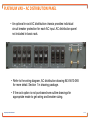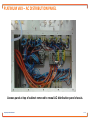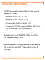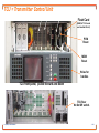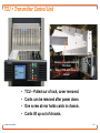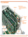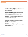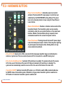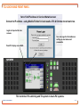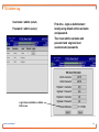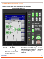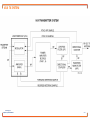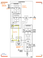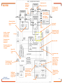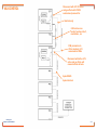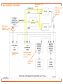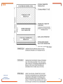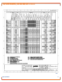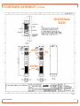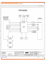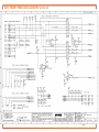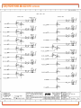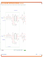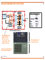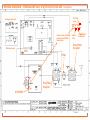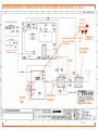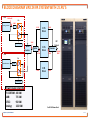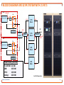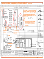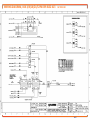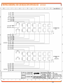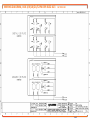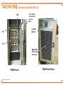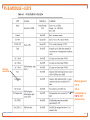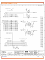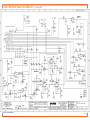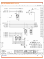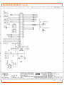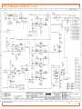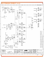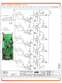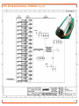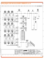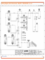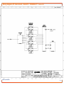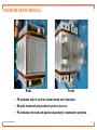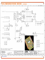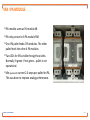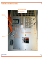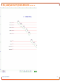
1
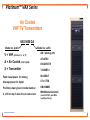
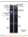
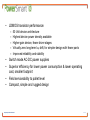
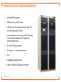
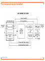
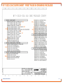
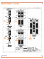
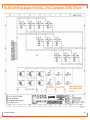
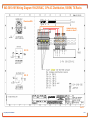
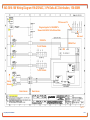
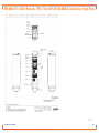
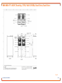
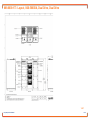
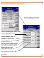
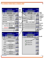
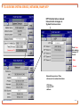
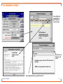
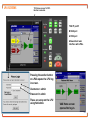
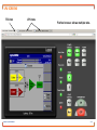
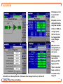
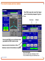
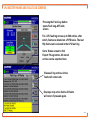
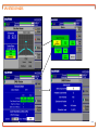
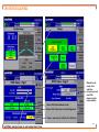
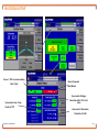
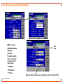
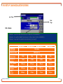
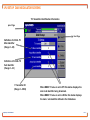
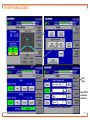
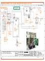
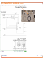
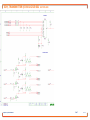
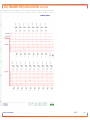
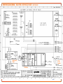
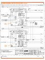
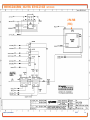
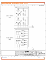
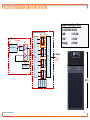
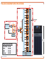
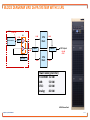
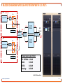
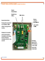
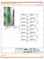
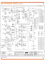
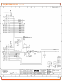
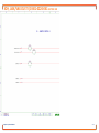
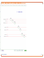
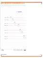
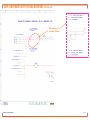
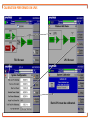
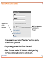
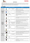
Lesson Plan Table of Contents February 27, 2012 1-1 VAX Air Cooled Overview 1-2 VAX Documentation 1-2A VAX Norkring Documentation 1-2B TCU Overview 1-3A TCU GUI Overview 1-4 LPU GUI Overview 2-0- Block Diagrams-Sparano 2-1 Outline-AC Distribution 2-2 System LPU 100-250 2-3 System 2 PA 2-4 System 4-32 PA 2-5 4_8 PA PAB 3-1 VAX PA Module 4-1 VAX Remote Connections 5-1 Calibration Overview 6-1 VAX_ALC 7-1 Customer Portal Welcome to Harris Broadcast Platinum VAX VHF Air Cooled Transmitters Presented by: Harris Training Department 6.4kW COFDM TV, 10kW DAB, 12kW ATSC, 16kW Analog Proprietary and Confidential 1-1.1 Platinum™ VAX Series Air Cooled VHF TV Transmitters VAX 5000 DA Model no. suffix Model no. prefix V = VHF (others U, L or F) A = Air Cooled (L for liquid) X = Transmitter AN = analog (ATV) AT=ATSC DV=DVB-T/H T2=DVBT2 Peak visual power for analog IS=ISDB-T Average power for digital CT= CTTB Pre-filter power given in model number. CM=CMMB A LPU on top if dual drive in same rack. MH=Mobile Handheld Proprietary and Confidential (used in ATSC, was MPH, need Synchrony) 1-1.2 AC Distribution Panel (option) LPU A Pre & Post Filter Coupler Samples LPU B (optional) TCU (Transmitter Control Unit) PAB 3 PAB 1 PAB 4 PAB 2 Up to 10kW DAB, 6.4kW COFDM TV, 12kW ATSC, 16kW Analog (dual drive) Proprietary and Confidential 1-1.3 PLATINUM™ VAX SERIES • VHF, Band III, air- cooled, multi-standard transmitter • Broadband design, frequency agile across VHF Band III (168-242MHz) • Hot pluggable PA modules • Hot pluggable power supplies • Incorporates Apex M2X multimedia exciter technology • RoHS & CE Compliant • Control from single LPU*, additional controller for dual drive options * Low Power Unit (includes exciter, system control & one PA Module) Proprietary and Confidential Front Air Plenum Option 1-1.4 • LDMOS transistor performance: – – – – – 50 Volt device architecture Highest device power density available Higher gain device, fewer driver stages Virtually zero long-term Idq drift, for simpler design with fewer parts Improved reliability and stability • Switch mode AC-DC power supplies • Superior efficiency for lower power consumption & lower operating cost, smaller footprint • Field serviceability to pallet level • Compact, simple and rugged design Proprietary and Confidential 1-1.5 PLATINUM VAX PRODUCT FAMILY (POWER LEVELS SHOWN ARE BEFORE FILTER) Up to 150W DAB, 100W COFDM TV, 180W ATSC, 250W Analog Up to 600W DAB, 400W COFDM TV, 750W ATSC, 1kW Analog Up to 2.5kW DAB, 1.6kW COFDM TV, 3kW ATSC, 4kW Analog Proprietary and Confidential Up to 5kW DAB, 3.2kW COFDM TV, 6kW ATSC, 8kW Analog (single drive shown, dual drive avail. in two racks) Up to 7.5kW DAB, 4.8kW COFDM TV, 9kW ATSC, 12kW Analog (single or dual drive available) Up to 10kW DAB, 6.4kW COFDM TV, 12kW ATSC, 16kW Analog (single or dual drive available) LPF is external on multiple cabinet transmitters. Racks bolt together for shipment. 1-1.6 PLATINUM™ VAX POWER SUPPLY Universal input 90 – 265 VAC 50/60Hz – Single Phase High-efficiency, auto ranging Power Supplies AC applied DC out Good power factor (>0.98, nominal) Low AC line harmonics Mounted on slides, hot pluggable via transmitter front One power supply per PA module for high reliability Power supply efficiency ~ 90% PSs ship installed. Straight slot screwdriver to remove. Proprietary and Confidential PA Modules VAX modules not interchangeable with DMB, or Z modules. 1-1.7 PLATINUM™ VAX RF PA MODULE – BAND III Two identical RF pallets per amplifier module 168-242 MHz frequency range Module Power rating: 200W COFDM 300W DAB 375W ATSC 500W analog Module Gain 21-23dB. Lightweight, hot-pluggable and Interchangeable Two LDMOS devices per module (one per pallet) Weight: 4.5kg (9.9 lb) Size: 229mm x 178mm x 102mm (9”D x 7”W x 4”H) Proprietary and Confidential FET 1-1.8 PLATINUM™ VAX – VHF PLATFORM 5 RU - 2 PA Chassis Pre-filter power levels up to: COFDM DAB ATSC Analog Cascaded PA’s Parallel PA’s 200 W 300 W 375 W 500W 400 W 600 W 750 W 1 kW 1 1 2 2 PA modules • Hot swappable Power Supply module • Hot swappable • 1:1 with PA module Control Interface to the transmitter system. Same as on 4/8 module PAB Proprietary and Confidential • Can’t change fans while on-air. • PA module backplanes contain LEDs (VSWR, Temp, Current) and protection circuits. • LEDs on backplane behind modules. 1-1.9 PLATINUM™ VAX – VHF PLATFORM PA BLOCK 16 RU amplifier chassis: PA , PS & LED locations on sticker PAB includes 4, 6 or 8 PAs. 8 PA unit has split IPA PAB power levels: 4 PAs 6 PAs 800 W 1.25 kW 1.25 kW 1.87 kW 1.5 kW 2.35 kW 2.0 kW 3.0 kW COFDM DAB ATSC Analog 8 PAs 1.6 kW 2.5 kW 3.0 kW 4.0 kW 8 1 1 2 IPA 3 4 5 6 7 8 Modular power supplies. IPA supplied by 50V buss. Control interface to the transmitter system RF power amplifiers (PA modules) Hinged front door with washable filter PA & PS # 1,3,5,7 & IPA removed for 4 PA version. Proprietary and Confidential PA & PS # 3, 6 & IPA removed for 6 PA version. 1-1.10 PLATINUM™ VAX – VHF PLATFORM PA BLOCK RS 485 and interlocks 1 8 RF output 7/16 DIN User Remote connector AC inputs, Powercon connectors 5, single speed, 50V fans on back door. Change entire door to change fans fast Hex wrench key (5/16” or 8mm) 5 fan LEDs - up to 3 fans can fail without overheating Flappers – prevent fan stalls at startup Proprietary and Confidential 1-1.11 PLATINUM™ VAX – POWER LEVELS Modules Modules Configuration Cabinets VAX-50DA, 50XX, 100AN, 60AT (1) 5RU LPU 0 or 1 1 1 VAX-150DA, 100XX, 250AN, 180AT (1) 5RU LPU 0 or 1 1 1 VAX-300DA, 200XX, 500AN, 375AT (1) 5RU LPU 0 or 1 1 1 VAX-600DA, 400XX, 1000AN, 750AT (1) 5RU LPU 0 or 1 2 2 PA IPA PS (1) 5RU LPU 1 1 0 or 1 (1) 5RU PAB 2 2 (1) 5RU LPU 1 1 0 or 1 VAX-600DA-A, 400XX-A, 1000AN-A, 750AT-A (1) 5RU PAB 2 2 (1) 5RU LPU 1 1 VAX-1250DA, 800XX, 2000AN, 1500AT 0 or 1 (1) 16RU PAB 4 4 (1) 5RU LPU 1 1 VAX-1875DA, 1250XX, 3000AN, 2250AT 0 or 1 (1) 16RU PAB 6 6 (1) 5RU LPU 1 1 VAX-2500DA, 1600XX, 4000AN, 3000AT 0 or 1 1 NOTE: (1) 16RU PABs 8 8 Module (1) 5RU LPU 1 1 “+ 2*” designation indicates the fans at the front of the LPU. Additional transmit- ter parameters, VAX-5000DA, 3200XX, 8000AN, 6000AT 1 or 2 2 (2) 16RU PABs 16 16 such as size, weight, and power consumption, may be found in the Outline Drawing, VAX (1) 5RU LPU 1 1 Transmitters. VAX-7500DA, 4800XX, 12000AN, 9000AT 2 3 (3) 16RU PABs 24 24 1 1 (1) 5RU LPU 4 VAX-10000DA, 6400XX, 16000AN, 12000AT 2 32 32 (4) 16RU PABs VAX-300DA-A, 200XX-A, 500AN-A, 375AT-A Proprietary and Confidential - A models discontinued Aug. 2012 1-1.12 VAX EFFICIENCY ESTIMATES Approximations: Single Cabinet Systems (two PABs) – 25% Larger Multi-Cabinet Systems – 30% Pallets – 40% PS – 90% LPU – 11.5% Proprietary and Confidential 1-1.13 PLATINUM VAX – OPERATING VOLTAGES Standalone = Rack w/o AC dist. panel or no rack. Just components up to 1 kW. – LPU (low power units): Single phase, 110 - 240VAC, IEC 15 & 20 47-63 Hz, one IEC C15 and one IEC C20 inlet. The two PA module PAB chassis has dual 100-240 VAC 50/60Hz single-phase feeds via IEC C20 inlets. The two inputs are completely independent and may be wired to separate AC phases for increased redundancy. The PAB four PA amplifier chassis has three 208-240 VAC 50/60Hz single-phase feeds via IEC C20 inlets. The three inputs are completely independent. The PAB eight PA amplifier chassis has three 208-240 RS485 & Interlocks LPU Rear Powercon RS485 & Interlocks VAC 50/60Hz single-phase feeds via Powercon inlets. The three inputs are completely independent. 8 Module PAB Rear Proprietary and Confidential 1-1.14 PLATINUM VAX – OPERATING VOLTAGES • Transmitters are configurable on-site for single or three phase AC connection. Loads are split to keep max components on line if phase is lost. • If three phase power is used then supply voltage (per phase) must be between 208 & 240VAC for LPUs and PABs. • Check voltage at plugs 1 at a time before initial turn on. • An optional in-rack AC distribution chassis (deluxe rack) provides individual circuit breaker protection for each AC input. AC distribution panel not included in basic rack. • Refer to the wiring diagram, AC distribution drawing 843-5610-065 for more detail. Proprietary and Confidential 1-1.15 PLATINUM VAX – AC DISTRIBUTION PANEL • An optional in-rack AC distribution chassis provides individual circuit breaker protection for each AC input. AC distribution panel not included in basic rack. • Refer to the wiring diagram, AC distribution drawing 843-5610-065 for more detail. Section 1 in drawing package. • If the rack option is not purchased see outline drawings for appropriate mode to get wiring and breaker sizing. Proprietary and Confidential 1-1.16 PLATINUM VAX – AC DISTRIBUTION PANEL • An optional in-rack AC distribution chassis that includes an emergency stop button, AC mains switch, and convenience outlet also available. Schuko Connector (without breaker) Wiring instructions for emergency stop button found on 839-8132-413 (Section 100, Sheet 1). Proprietary and Confidential 1-1.17 PLATINUM VAX – AC DISTRIBUTION PANEL Access panel at top of cabinet removed to reveal AC distribution panel chassis. Proprietary and Confidential 1-1.18 PLATINUM VAX – OPERATING VOLTAGES • The PAB chassis accepts these mains configurations when appropriate external wiring is provided: • Single-phase 208V-240V (L1+N, L1+N, L1+N) • Single-phase 208V-240V (L1+L2, L1+L2, L1+L2) • Three-phase “delta”, 208V-240V (L1+L2, L2+L3, L3+L1) • Three-phase “wye”, 360V-415V (measures 208-240VAC L1+N, L2+N, L3+N) (only time neutral is used….do not fuse or switch neutral) • Components always fed with 208-240VAC. <190VAC gives AC1, 2 or 3 fault. Restarts when voltages >190VAC. • The four PA module PAB is essentially the same as the eight PA module PAB, except for the number of PAs, PSs and a different combiner (8x output assy.). Proprietary and Confidential 1-1.19 PLATINUM VAX – OPERATING VOLTAGES • Since the three mains inputs are completely independent, it is not necessary to observe a certain phase rotation or even phase balance. • The PAB chassis can operate indefinitely (at a reduced power) with one or two of the mains inputs missing. The internal power supplies connected to each input will continue to operate provided that the incoming mains power at that input falls within the voltage range indicated above. Proprietary and Confidential 1-1.20 PLATINUM VAX OPTIONS/ACCESSORIES • Internal GPS receiver • GPS antenna and RF cable • UPS to keep LPU exciter section and TCU alive during power failure • Internal battery back up for LPU. Provides 15-20 minutes backup for frequency processing circuits. • Dual LPU’s (dual drives) • Air plenum – ducted air system • SFN • Emergency Stop Button • Isolator Switch (European versions) Proprietary and Confidential 1-1.21 PLATINUM VAX BLOCK DIAGRAM Proprietary and Confidential 1-1.22 VAX DOCUMENTATION PACKAGE 988-2717-001 VAX Documentation Package Contains: Technical Manual 888-2717-001 (English) Drawing Package 917-2323-234 Note: Manuals not yet available in other languages. Proprietary and Confidential 1-2.1 817-2323-234 COVER SHEET FIRST PAGE IN DRAWING PACKAGE 2-1 2-1 2-5 3-1 2-4 2-3 2-5 2-1 2-1 2-1 2-3 2-2 2-5 Proprietary and Confidential 1-2.2 WIRING DIAGRAM 10-150 W 843-5610-021 (1 of 2) Section 200 Examples of Drawing Details Number of Conductors (8/) Wire Number (3) To / From Page / Section (2 / D8) Drawing Vert. Axis Signal Name (INTRFC) Revision Level Drawing. Hor. Axis Revision Level Proprietary and Confidential Sheet No. ( 1of 2 ) Drawing No. 1-2.3 WIRING DIAGRAM 10-150 W 843-5610-021 (2 of 2) Section 200 Examples of Drawing Details To / From Page / Section (1 / A6) Signal Name (INTRFC) Proprietary and Confidential Sheet No. (2 of 2) Drawing No. 1-2.4 843-5610-194 Phase 1 Rack-UPS 2PA Modules 2PA Modules Proprietary and Confidential 4PA Modules 4PA Modules 8PA Modules 1IPAModule 1-2A.1 843-5610-165 Wiring Diagram 198-250VAC, 3-Ph AC Distribution, 5000W 208-240V 3PH Delta Fuse size given on 839-8464-263 L1, L2 & L3 Safety Ground Applies to 5kW Txer, 16 PA modules, 2 IPA modules. Rack Exterior Rack Interior 1 of 4 Proprietary and Confidential 1-2A.2 843-5610-165 Wiring Diagram 198-250VAC, 3-Ph AC Distribution 5000W, TX Racks AC outlet strip is in center rack. See 843-5610-194 right side. TCU has one PS. L1 230VAC Out L2 Not used 230VAC In Safety Ground UPS Rack Exterior Rack Interior 2 of 4 Proprietary and Confidential 1-2A.3 843-5610-165 Wiring Diagram 198-250VAC, 3-Ph AC Distribution, 5000W, TX Racks PowerCon-20A IEC-19 (16A) IEC-13 (10A) Panel used in left and right cabinets but not in center. 3 of 4 Proprietary and Confidential 1-2A.4 843-5610-165 Wiring Diagram 198-250VAC, 3-Ph AC Distribution, 5000W, TX Racks Powercon-20A Jumpers here as shown on sheet 1. IEC-19 IEC-13 4 of 4 Proprietary and Confidential 1-2A.5 843-5610-166 Wiring Diagram 198-250VAC, 3-Ph Delta AC Distribution, 150-600W TCU has one PS Diagram Applies To 300-600W Tx Shown In 843-5610-194 Left Hand Side L1 L2 Not used 230VAC In 230VAC Out Tx 2 AC Outlets UPS Tx 1AC Outlets Safety Ground Rack Exterior Rack Interior 1 of 1 Proprietary and Confidential 1-2A.6 843-5610-167 Wiring Diagram 198-250VAC, 3-Ph Delta AC Distribution, 1250-2500W To Sheet-2 L3 L2 230VAC In from Inverter L1 UPS Diagram Applies To 1250-2500W Tx Shown In 843-5610-194 Center Safety Ground Rack Exterior Rack Interior 1 of 4 Proprietary and Confidential 1-2A.7 843-5610-167 Wiring Diagram 198-250VAC, 3-Ph Delta AC Distribution, 1250-2500W 230VAC Single Phase From Inverter (Sheet 1) L3 L2 L1 Safety Ground Diagram Applies To 1250-2500W Tx Shown In 843-5610-194 Center Rack Exterior Rack Interior 2 of 4 Proprietary and Confidential 1-2A.8 843-5610-167 Wiring Diagram 198-250VAC, 3-Ph Delta AC Distribution, 1250-2500W Diagram Applies To 1250-2500W Tx Shown In 843-5610-194 Center PowerCon-20A IEC-19 (16A) IEC-13 (10A) 3 of 4 Proprietary and Confidential 1-2A.9 843-5610-167 Wiring Diagram 198-250VAC, 3-Ph Delta AC Distribution, 1250-2500W Powercon-20A Jumpers Here As Shown On Sheet 1 IEC-19 IEC-13 Diagram Applies To 1250-2500W Tx Shown In 843-5610-194 Center. 4 of 4 Proprietary and Confidential 1-2A.10 843-5610-170 SmartPack Assembly 981-0090-170 1 of 1 Proprietary and Confidential 1-2A.11 853-0000-169 ASSY, Rack-Up, 37RU, 70 cm DP, 2X FAX-600DA, Dual Drive, Dual Drive 1 of 1 Proprietary and Confidential 1-2A.12 853-0000-170 ASSY, Rack-Up, 37RU, 70cm DP, 2X FAX-600DA, Dual Drive, Single Drive 1 of 1 Proprietary and Confidential 1-2A.13 888-0000-171 ASSY, Rack-Up, 37RU, VAX-1250DA, Dual Drive, Dual Drive 1 of 1 Proprietary and Confidential 1-2A.14 888-0000-172 ASSY, VAX-1250DA, Single Drive, Single Drive 1 of 1 Proprietary and Confidential 1-2A.15 888-0000-173 Layout, VAX-5000DA, Dual Drive, Dual Drive 1 of 1 Proprietary and Confidential 1-2A.16 TCU = TRANSMITTER CONTROL UNIT TCU contains GUI (graphical user interface panel PC). LPU Battery for real time clock on PCM card. Must be installed on site. (CR1025, DC1025 Lithium 3V, 10mm) Transmitter stays on air if TCU fails or is TCU removed. TCU cards are not hot swappable. Remove power from TCU before removing cards. LPU TCU used with dual LPUs Proprietary and Confidential 1-2B.1 TCU = Transmitter Control Unit GUI screen calibration can be accessed during reboot. Tap screen when “Touch screen to calibrate.” text appears. 5 point cal begins. Reboot of TCU takes about 2 minutes. Transmitter will stay on air if reset button on PCM or MCM card is used. Proprietary and Confidential 1-2B.2 TCU = Transmitter Control Unit Flash Card (2GB,FAT 16 Format use Sandisk Ultra II) PCM Reset MCM Reset Holes for handles TCU front panel, pulled forward and down TCU Rear No On/Off switch. Proprietary and Confidential 1-2B.3 TCU = Transmitter Control Unit Remove screw each side to tip TCU down. Support TCU while removing screws ! • TCU – Pulled our of rack, cover removed. • Cards can be removed after power down. • One screw at rear holds cards in chassis. • Cards lift up out of chassis. Proprietary and Confidential 1-2B.4 TCU = Transmitter Control Unit TCU – Pulled out from rack and pivoted downward Proprietary and Confidential 1-2B.5 TCU COMPONENTS PCM Battery PS Board Behind front panel: • LCD board, driver LCD display • User interface board (behind LED switches) Main Control Module MCM Processor Control Module PCM (uprocessor daughter board) Customer I/O Board Transmitter Interface Proprietary and Confidential Backplane Board 1-2B.6 TCU - CARDS • Master Control Module (MCM) – Responsible for transmitter and TCU board control. • Processor Control Module (PCM) – Enhanced customer interface, web page server, SMP info to remote users. • Customer I/O - Provides for all customer parallel interfaces connections on I/O panel at top of • TX Interface – Interfaces to several subsystems for dual LPUs, RF switch, system interlock. • PS 1 & 2 - Redundant 24V power supplies. Produce supply voltage for boards in TCU. Proprietary and Confidential 1-2B.7 TCU – HARDWARE BUTTONS • Power Control Auto/Manual : Automatic power level control activated. The transmitter RF output power is held to the level established by the FWD PWR REF setting. Manual: The power level can be manually raised or lower using the Power Raise or Lower buttons. • Remote Enable/Disable: Enables or disables remote control of the transmitter. Enable: The transmitter system can be remotely controlled by either the user parallel interface or the remote web interface. Disable: The transmitter will only respond to local commands issued from the various front panel controls. • Power Raise/Lower: Pressing raise will increase RF power output. Lower decreases power output. Caution: There may be a slight lag in system power level response time. Holding buttons in may cause undesired overshoots. • Drive (LPU) A/B: Selects which LPU is connected to the high power amplifier stages and ultimately the antenna or system load. The non-selected (reserve) LPU is connected to a small RF dummy load. • Drive Control Auto/Manual Auto: Automatic LPU switchover is enabled. The system will select the reserve LPU in the event of the failure of the main LPU. Manual: Automatic LPU switchover is disabled. The system will not automatically select the reserve LPU in the event of the failure of the main LPU. • Transmitter ON/OFF: Switches transmitter RF output on or off. Built-in switch LEDs provide feedback as to ON/OFF status of transmitter system. ON button is lit green when transmitter system is switched on. OFF button is lit red when transmitter system is switched off. Proprietary and Confidential 1-2B.8 TCU LOG IN AND FRONT PANEL Set or find IP address in Service>Netwrk screen Connect to IP address - using Mozilla Firefox for best results. IE 8 & Chrome should work too. Login not required to view screens. See next page for information on setting up usernames and passwords. Panel PC display runs LINUX. TCU controls LPU switching and TX system in dual LPU systems. Proprietary and Confidential 1-3A1 TCU Admin Log Username = admin (default) Password = admin (default) First-time - login as Administrator locally using default admin username and password. Then reset admin username and password and engineer level username and passwords. Login timeout settable on Admin Edit screen. Proprietary and Confidential 1-3A2 TCU HOME SCREEN & FRONT PANEL BUTTONS TCU and LPU will have 1 Admin, 1 Eng, 1 Operator, & multiple Guest levels Logins. Auto is normal. Man disables ALC. Buttons work (except for Remote) on remote GUI with web browser if logged in and Remote enabled. Active LPU GUI Panel PC TCU event log. Go to active LPU for more detailed fault log info. Proprietary and Confidential Yellow LED indicates missing RTAC sample in this case. Need to check active LPU for warnings and errors. Not always listed in TCU event log. Auto can’t be selected with a bad LPU. 1-3A3 TCU HOME SCREEN, EVENT LOG, & SYSTEM SERVICE There can be up to 1,000 faults stored in the TCU Event Log, after which, faults are deleted on a FIFO (First In First Out) basis. The TCU event log can be printed or saved by double clicking on the diskette or printer icons. Time is in 24 hr. format (HH/MM). Active faults red. Active warnings yellow. Inactive items are gray background. White=selected Dark=not selected 1x set up at factory MM/DD/YY DD/MM/YYYY YYYY/MM/DD Selectable filtering Proprietary and Confidential 1-3A4 TCU SCREENS SYSTEM SERVICE, CONFIGURATION These Config settings go out to LPU’s. Low power output warning level – yellow bar. 80% typ. Low power output fault level – red bar. High power output fault – red bar Sets 100% power output level on bar Set desired TPO (W) here. Power setting in active LPU. May be lower than Fwd Power Ref. if bad module or in foldback. Set desired TPO % here (0-100%). Limited by Nominal Power Out Frequency in MHz. Sets both LPU’s. Proprietary and Confidential 1-3A5 TCU SCREENS SYSTEM SERVICE, CONFIGURATION Reflected power level that initiates foldback in Watts. Reflected power that initiates foldback (14%). 4% is around 1.5:1 VSWR How far will Tx foldback 50-100%. 100% foldback = zero watts output How long Tx stays in foldback 5 - 120 seconds. Tries to increase power in 20% increments. Proprietary and Confidential 1-3A6 TCU SCREENS SYSTEM SERVICE, NETWORK, SNMP Set by SNMP user. Watch for leading spaces. Only supports versions 1 & 2C at this time. Simple network management protocol. Use with MIBs to control system. Trap monitor used in networks, CS Navigator management system. Base MIB Proprietary and Confidential 1-3A7 TCU SCREENS SYSTEM SERVICE, NETWORK, SNMP, NTP NTP Disabled allows manual time and date changes on System Service screen. Press Save after making changes. Or Cancel. Save Cancel Network time protocol. Time references from network locations. LPU takes only one NTP address. Proprietary and Confidential 1-3A8 TCU SCREENS SYSTEM SERVICE, CONFIGURATION & VERSION These change with PCM update Refer to these screens when working with Harris field service. Proprietary and Confidential 1-3A9 TCU FIRMWARE UPDATE Press Activate to update PCM…or press Delete to remove the file. PCM software is upgradeable using the Firmware Management screen. View displays software release notes. Browse for .tcu filename and select. Bar will turn green and read 100% when file is uploaded. MCM currently updates via flash card. Press Upload button to upload file to TCU. Proprietary and Confidential 1-3A10 TCU SOFTWARE COMPONENTS 861-1142-012 UAX/VAX SW, Customer I_O (JTAG, XYLINX programmer needed) 861-1142-022 UAX/VAX SW, UCP, Main Control Module (.ace file on flash card, must rename old file extension .old) 861-1150-012 S/W,TCU,PCM II,PPC,UAX / VAX, Process Control Module (.tcu file used in Firmware Update) 861-1142-142 UAX/VAX SW, UCP, TCU Interface (JTAG, XYLINX programmer needed) 861-1142-052 SW, UCP, UAX/VAX Panel PC (LINUX and flash card in panel pc, use hook to remove and replace flash card. Flash card is specially formatted and acts as hard drive for panel PC.) Note: The PCM software is currently the only TCU software upgradeable via Firmware Update screen in web GUI. MCM may also be upgradeable via Firmware Update screen in the future. Proprietary and Confidential 1-3A11 LPU SCREENS TCU Home screen Tx OFF. Exciter A selected. TCU IP: port# B= 848 port A= 592 port Allows direct web interface with LPUs. Pressing the exciter button on LPUA opens the LPU log in screen. Username = admin No login = Guest Mode Password = admin These are setup on the LPU using NetAdmin. Proprietary and Confidential VAX Home screen opens after log-in. 1-4A.1 LPU SCREENS TCU tab LPU tabs Firefox browser allows multiple tabs. Proprietary and Confidential 1-4A.2 LPU SCREENS TCU Screen Proprietary and Confidential 1-4A.3 LPU SCREENS PA module current is sum of both pallets. IPA pallet currents display alternately every few seconds. All fans in PAB run at single speed. LPU rear fan can be changed while on-air (change assy.) PAB fans can be changed while onair ( change full door assy.) PA module temp max is 125oC. Warning at 115oC. Typical is 65oC. 100oC is max load temp. (combiner) With UPS set to Always Restrike. Otherwise either Always Restrike or 3-Strike Off. Proprietary and Confidential 3-Strike Off has 15 second window. No ambient temp trip point. 1-4A.4 LPU EXCITER HOME AND RTAC SCREENS Post RTAC output after mask filter. Signal doesn’t immediately disappear if signal is lost. Successes Attempts Pressing the RTAC box on the Exciter Home page opens the RTAC control screen. Linear corrects for distortions in filter. Nonlinear corrects for distortions in amplifier. RTAC State Disabled: inactive / man AGC mode / Calibration / Tx-Off / Tx-on, but failed to ramp up to actual Power level Proprietary and Confidential 1-4A.5 LPU EXCITER HOME AND FAULT LOG SCREENS Pressing the Fault Log button opens Fault Log-All Faults screen. The LPU fault log stores up to 500 entries, after which, faults are deleted on a FIFO basis. The last fifty faults can be viewed in the LPU fault log Go to Status screen to find Export FltLog button. All stored entries can be exported here. Erases all log entries. Active faults will come back. Displays only active faults. All faults will return if pressed again. Proprietary and Confidential 1-4A.6 LPU STATUS PAGES Behavior in case of Input Signal Level Compression -11 dB: ETI recognized correctly, no Byte Errors, no CRC errors -12 db: ETI still recognized correctly, but Byte Errors present, no CRC errors - 13 db: No ETI input signal detected Proprietary and Confidential CRC-Control ON: seamless switch if CRC errors exceed threshold OFF: errors reported, but no switch (unless errors would cause a mute). 1-4A.7 LPU STATUS PAGES Proprietary and Confidential 1-4A.8 LPU STATUS DUC/RTAC Manual is test mode. Auto switches between pre and post filter downconverter input samples. Green= OK, Red=feedback invalid Green= OK, Yellow=low level, Red=high level Yellow = low level (<6.5 dB) for IF or RF atten. Proprietary and Confidential Set RTAC sample levels to just below black lines. 1-4A.9 LPU STATUS OUTPUT Green = UDC is communicating Red = Fault Green= Unmuted Red= Muted Upconverter Voltages Upconverter Amp. Temp. Faults at 70oC Should be within 10% of ref. value. Upconverter Attenuation Should be >6.5 dB Proprietary and Confidential 1-4A.10 LPU STATUS TRANSMITTER I/O Green= Active Blue = Not Active Proprietary and Confidential 1-4A.11 LPU STATUS PFRU Holdover = time remaining (hours) till shutdown if GPS is lost. Readiness: Green if >90% Red if<90% White if 1 PPS ref. lost Proprietary and Confidential 1-4A.12 LPU STATUS PFRU Behaviour in case of GPS loss Limit value for shutdown: 20% of the protection interval of the DAB transmission mode PFRU drift rate spec.: < 18us in 24 hours. Mode I: Mode II: Mode III: Mode IV: Proprietary and Confidential GI = 246 us (20% = 49.2us) GI = 62 us ( 20% = 12.4us) GI = 31 us ( 20% = 6.2us) GI = 123 us ( 20% = 24.6us) >24hr timeout 16hr timeout limit 8hr timeout limit >24hr timeout 1-4A.13 LPU STATUS BATTERY BACKUP Proprietary and Confidential 1-4A.14 LPU STATUS REVISIONS Build Version should appear as shown (part # REV#). If the LPU does not have all the proper software revisions installed for a particular build then “Customer Special” will be displayed. The full build should be installed when updating software. The full build contains all matching software components. Proprietary and Confidential 1-4A.15 LPU STATUS PAGES Expansion board used for DVBT-2. Proprietary and Confidential 1-4A.16 LPU SETUP USER SETTINGS PAGES Logged in using: Logged in using: Username: admin Username: netadmin Password: admin Password: harris Proprietary and Confidential 1-4A.17 LPU SETUP USER SETTINGS PAGES Must log out to exit. Logged in using: netadmin harris Can’t change NetAdmin login or password via GUI. Use serial port on rear of LPU and Teraterm. Proprietary and Confidential 1-4A.18 LPU SETUP SYSTEM SETTINGS Main header for each LPU page (e.g. Station name) Unlock Feature Key or modulation standard (more info: next page) Feature key must be changed as options are added. Contact Harris Sales. Proprietary and Confidential Changing TX-Model will cause FWD-Power Reference = 0 ! 1-4A.19 OVERVIEW MODUL. STANDARDS APEX-M2X System and Modulation Standards ATSC standard American Television Standards Committee, North American 8VSB digital TV ATSC A110 Single frequency network standard for ATSC ATSC MH Mobile TV standard for ATSC (ATSC A/153) DVB-T Digital Video Broadcasting - Terrestrial, European digital TV standard, COFDM DVB-H Digital Video Broadcasting - Handheld, European digital TV standard, COFDM DAB Digital Audio Broadcasting, European digital radio standard, COFDM DMB Digital Multimedia Broadcasting, Korean digital TV standard transporting video information using the DAB standard. ISDB-T South American and Japanese digital TV standard (Integrated Services Digital Broadcasting CMMB China Mobile Multimedia Broadcasting CTTB China Terrestrial Television Broadcasting ATV Analog television PAL = Phase Alternate Line, analog TV standard (Europe and other Countries) system M FLO Proprietary and Confidential NTSC = National Television Standards Committee, USA analog TV standard, Qualcomm mobile TV ( FLO = Forward Link Only) 1-4A.20 LPU SETUP SYSTEM SETTINGS UTC: Universal Time Coordinated UTC Sources: * None * GPS * NTP (Network Time Protocol) Max. Offset: -13h….+13h Proprietary and Confidential 1-4A.21 LPU SETUP TRANSMITTER I/O, PRFU Transmitter I/O Signal that goes to Monitor port on back of LPU. This screen not present in all modulations. VAX: ETI Monitor Output selectable in Menu 2.3.3. Proprietary and Confidential 1-4A.22 LPU SETUP TRANSMITTER I/O, PRFU Transmitter I/O Set frequency here w/o TCU. Internal GPS Ext. 1pp Ext. 10 MHz Manual (Only GPS & 1PPS in SFN) Used in Manual mode only. (rough tuning range: 10MHz +/- 10Hz ~ 9.99999140561 MHz to ~ 10.0000107215 MHz ) Proprietary and Confidential 1-4A.23 LPU SETUP AND REMOTE COMMUNICATIONS Set for LPU A Need front MAC address for new feature key. General IP Settings for LPU A and LPU B Proprietary and Confidential 1-4A.24 LPU SETUP AND REMOTE COMMUNICATIONS Can’t be set same on both LPU’s. Will cause LPU’s to cycle ON/OF. Proprietary and Confidential 1-4A.25 LPU SETUP DAB MODULATOR SCREENS Input signal Information: ---- : Misssing: NI: NA: Input not activated / not considered Signal expected, but not present ETI signal with Layer NI (Network Independent) ETI signal with ETI NA (Network Adapted) Additional ETI input information visible in the DABModulator Status-Screen Comes on to this after power bump. Manual or automatic switching mode (Seamless switching) between ETI 1 and ETI 2 input Seamless switching: more info see next page Proprietary and Confidential Yes if second input available. 1-4A.26 SEAMLESS SWITCHING OF ETI-INPUTS ETI 1 G703 Interface G704 Framer RS Decoder CRC Control TS Processing ETI 2 Control ETI 2 G703 Interface G704 Framer • Two independent ETI Input Terminals • Seamless switching frame by frame • Indication of corrupted bytes per RS - block (ETI(NA)) Proprietary and Confidential RS Decoder CRC Control TS Processing • CRC check in EOF and EOH for both inputs • Automatic selection of the stream with the better quality 1-4A.27 Overview Delay Times in DAB M U X Network Adapter ETI (LI) LPU SETUP DAB MODULATOR SCREENS Adjust ETI Static Delay = Processing Delay + Static Delay Comp COFDM 200ms = 175.4569 ms + 24.5432 ms Processing Time Processing Time + + This means no values lower than the processing delay can be entered Calculated Delay Time (Dynamic Delay) Static Delay Processing Delay Times: Dyn. Delay OFF: 175.4569 ms Max. Network Delay Proprietary and Confidential Sum Static Delays = constant Dyn. Delay ON: 100.6074 ms 1-4A.28 LPU SETUP DAB MODULATOR SCREENS MNSC – Control (Multiplex Network Signaling Channel) Next Page Parameters which can be controlled remotely via ETI input signal: • DAB-Mode • Offset Delay • TII Value Selection which signal goes to monitoring output on back of LPU Proprietary and Confidential 1-4A.29 LPU SETUP DAB MODULATOR SCREENS prev. Page Next Page DAB – Modes: Mode 1: used for DAB Transmission in Band 3 (176-240MHz) Mode 2, 4: used for DAB Transmission in the L-Band (1452-1492MHz) Mode 3: reserved for satellite transmission (not used) DAB Mode 1 DAB Mode 2 Frequency bandwidth Proprietary and Confidential DAB Mode 4 1536 kHz Useful bit rate Number of subcarriers Subcarrier spacing Total symbol duration Useful symbol duration Guard interval DAB Mode 3 1500 kbit / s 1536 384 192 768 1 kHz 4 kHz 8 kHz 2kHz 1246 µs 312 µs 156 µs 623 µs 1000 µs 250 µs 125 µs 500 µs 246 µs 62 µs 31 µs 123 µs 1-4A.30 LPU SETUP DAB MODULATOR SCREENS TII: Tansmitter Identification Information prev. Page Next Page Definition of LOCAL TII Main Identifier (Range 0 – 69) Definition of LOCAL TII Sub Identifier (Range 0 – 23) = Transmitter ID (Range 0 – 9999) When MNSC TII value is set to ETI this status displays the main /sub identifier being broadcast. When MNSC TII value is set to LOCAL this status displays the main / sub identifier defined in the field above Proprietary and Confidential 1-4A.31 LPU SETUP DAB MODULATOR SCREENS prev. Page Next Page Definition of crambling Key Range: 0 - 255 Legacy SNF Compliance: Difference in insertion of padding bits for the Main Service Channel of a DAB signal HCAST1: insertion of padding bits takes place before Convolutional Coder. HCAST2: Padding bits are added after the Convolutional Coder and puncturing (= fully compliant to the ETSI-specifications) In new DAB SFN-Networks HCAST 2 will be the correct setting Proprietary and Confidential 1-4A.32 LPU SETUP DAB MODULATOR SCREENS prev. Page 3 operation modes: • OFF = Online Operation: a valid DAB-Signal is produced in mode 1,2,3 or 4 (= normal operation) Single Tone will allow to measure frequency stability at the Tx-Output • Online = Online Testmode: PRBS (Pseudo Random Binary Sequence) signal is superimposed on a selected subchannel. • 3G = Local test operation: fixed multiplex structure acc. to the 3rd generation including FIC ( Fast information Channel - acc. ETS 300 401 of May 97) is produced. Selected Subchannel is overlapped with PRBS, data of all other subchannels are set to „0“ Proprietary and Confidential 1-4A.33 LPU SETUP DAB DUC/RTAC Next Page Save RTAC correction sets here, Select stored RTAC value to use. Proprietary and Confidential 1-4A.34 LPU SETUP DAB DUC/RTAC Factory Settings: DVBT/ISDBT Non-Linear 7.8 Max Crest Factor 13.0 Before RTAC. ATSC Non-Linear 7.0 Max Crest Factor 11.0 Disable Peak Reduction for Analog operation. DAB: NLR = 6dB / MCF = 10dB Range: 4 – 9 Range: 6 - 13 Non-Linear-Range (NLR) is a filtered clipping ( influence to MER) Max Crest Factor (MCF) is a overall clipping Modulator Bandpass Filter NLR Clipper Adaptive Predistortion RTAC Power Amplifier On Channel RF Proprietary and Confidential Mixer 140 MHz IF DA MCF Clipper 1-4A.35 LPU SETUP DAB DUC/RTAC Helps filter roll off at lower channels (IF=140MHz) Corrects for down converter tilt +/- 10. Must toggle RTAC on and OFF after running for several correction cycles. Example: +9,5 NON-LINEAR Profiles: LINEAR Profiles: • BASIC. most standard mask filters. • SHORT • LONG • MAX • BASIC OFFSET • SHORT OFFSET • LONG OFFSET filter combining • MAX OFFSET Proprietary and Confidential • BASIC reflective filter • BASIC MEMORY reflective filter • PROFILE 3 • PROFILE 4 • HIGH reflective filter • HIGH MEMORY reflective filter • PROFILE 7 (Avoid in DAB) • PROFILE 8 • PROFILE 9 in CTTB & ISDBT 1-4A.36 VAX TX SYSTEM Drawing 4.pdf Proprietary and Confidential 2-0.1 VAX LPU BLOCK Drawing 3a.pdf Proprietary and Confidential 2-0.2 VAX LPU MODULATOR To TCU UDC Drawing 3b.pdf Proprietary and Confidential 2-0.3 VAX LPU AMPLIFIER Amp approx. 40% efficiency. 10-100 mW 10-180 W Keeps PS On. Fwd, Ref, Mute, Master/Slave Drawing 3c.pdf Proprietary and Confidential 2-0.4 Reflected power goes to loads in splitters. VAX PAB Pallet Idle I=1.5A Module Idle I=3.0A o 90 offsets give Z cancellation and handle reflected power. W W Y Y 16 way combiner. o 125 C. load temp. max. Highest value displayed. Alternates display between IPA current values Loop current keeps PS on. All in phase If pulling 1 module turns off another module suspect bad reject loads. Comparator in each module. PA samples <1A triggers PS off. 50V fans Transmission line arc shuts all modules off. Diode Or’ed 50V PS modules off but state is On = all modules unplugged. Back of PA B above fan door. Long board at top rear. General restart for arcing. On cmd every 8 sec. if PS off but state on. Control light lit after 3 attemps. 20 analog lines. Not used. Available for user remote. DB25. Drawing 5a.pdf Proprietary and Confidential On/Off state via RS485. On pulse 100 mS long.To LPU ½ sec. delay before restarts begin. Unlimited restarts. Based on trailing edge of AC mains fault. Triggered when PA block is on but 50V shared not present. Info only. 2-0.5 VAX CONTROL Disconnect with LPU #1 active and go off-air until LPU #2 selected and pressed On. Interlock only CAN carries core exciter functions like F, modulation , etc. PAB parameters to LPUs, interlock, LPU commands to PABs Disconnect with either LPU active and go off-air until connected back to back. 2 pins RS485 2 pins interlock Drawing 1.pdf Proprietary and Confidential 2-0.6 VAX CONTROL TCU DETAIL Master/Slave, TCU present CAN carries core exciter parameters (freq, mod., etc.) 50 pin ribbon cables for parallel remote Parallel remote interface Specific for VAX, connects MCM to rest of Tx. Drives web server Drawing 6a.pdf Proprietary and Confidential 2-0.7 VAX TX SYSTEM (ALC DETAIL) Pin diode for analog UDC out 70mW with 30mW headroom for ALC. (in exciter) DC error signal DAC # 200 power rising Software Functions DAC #500 @ full power Digital error signal (negative feedback) Comparator (software) SPI Bus (serial protocol interface) DC Proprietary and Confidential Drawing 7.pdf RF Gain max when Tx cool. Decreases during warm-up. 20% (-1.0dB drop normal.) 2-0.8 SFN Drawing 2a.pdf Drawing 2b.pdf Proprietary and Confidential 2-0.9 OUTLINE DRAWING, VAX 839-8464-263 SECTION 100 LPU 2PA PAB VAX 2/4/8 PA Standalone LPU 4/8 PA PAB 1 of 2 Proprietary and Confidential 2-1.1 OUTILINE DRAWING, UAX 843-8464-263 SECTION 100 2 of 2 Proprietary and Confidential 2-1.2 OUTLINE DRAWING, UAX 839-8464-279 SECTION 100 VAX 4/8 PA Racked SD & DD LPUs TCU 4/8 PA PAB 1 of 1 Proprietary and Confidential 2-1.3 OUTLINE DRAWING, VAX 839-8464-280 SECTION 100 VAX 16 PA Racked SD & DD LPUs TCU 8 PA PAB 1 of 1 Proprietary and Confidential 2-1.4 OUTLINE DRAWING, UAX 839-8464-281 SECTION 100 VAX 24 PA Racked SD & DD LPU TCU LPU 8 PA PAB 1 of 1 Proprietary and Confidential 2-1.5 OUTLINE DRAWING, UAX 839-8464-282 SECTION 100 VAX 32 PA Racked SD & DD LPU TCU LPU 8 PA PAB 1 of 1 Proprietary and Confidential 2-1.6 OUTLINE DRAWING, UAX 839-8464-283 SECTION 100 VAX 2 PA Racked SD and DD LPU 2 PA PAB TCU LPUs 2 PA PAB 1 of 1 Proprietary and Confidential 2-1.7 AC DISTRIBUTION PANEL CONNECTION (TOP OF CABINET) Access panel removed. TB2 TB1 WAGO connectons • Single-phase 208-240V (L1 +N, L1+N, L1+N) OK Screw connections • Single-phase 208-240V (L1+L2, L1+L2, L1+L2) • Three-phase “Delta“ (or Wye, no neutral) (, 208-240V (L1+L2, L2+L3, L3+L1) • Three-phase “Wye", 360V-415V (measures 208-240VAC L1+N, L2+N, L3+N) Note: Systems that utilize three-phase "wye" AC mains should not use a fuse in the neutral leg. Failure to properly connect the neutral wire can result in damage to the transmitter components and will void the warranty. Proprietary and Confidential 2-1.8 AC DISTRIBUTION PANEL AC Distribution panel AC Distribution panel with AC mains switch, emergency off button, and outlet Proprietary and Confidential 2-1.9 VAX AC DISTRIBUTION, PANEL 843-5610-065 Outside Panel AC Mains SECTION 100 Inside Panel Optional Emergency Off Button. TB-1 TB-2 Customer Cut Offs Customer UPS 3PH WYE (With Neutral), AC Distribution Panel 350-450 VAC SD or DD 1 or 2 PABs 1 of 5 Proprietary and Confidential 2-1.10 VAX AC DISTRIBUTION, PANEL 843-5610-065 Outside Panel SECTION 100 Inside Panel Optional Emergency Off Button AC Mains TB-1 TB-2 Customer Cut Offs TB-1 Customer UPS 3PH Delta (or Wye, no neutral) AC Distribution Panel 198-250 VAC SD or DD 1 or 2 PABs 2 of 5 Proprietary and Confidential 2-1.11 VAX AC DISTRIBUTION, PANEL 843-5610-065 SECTION 100 Breakers On Front Panel 10A 15A 15A 10A AC Distribution Panel 1 or 2 PABs SD or DD TB2 Breakers For PAB 1 (Inputs A, B, C) Plugs On Rear Panel 20A 20A 20A Breakers For PAB 2 (Inputs A, B, C) 16A 20A 20A 20A 20A 10A 3 of 5 Proprietary and Confidential 2-1.12 VAX AC DISTRIBUTION, PANEL 843-5610-065 SECTION 100 TB-2 TB-1 20A 16A 10A 3PH WYE, AC Distribution Panel 350-450 VAC SD or DD 1 or 2 PABs 4 of 5 Proprietary and Confidential 2-1.13 VAX AC DISTRIBUTION, PANEL 843-5610-065 SECTION 100 TB-2 TB-1 20A 16A 10A 3PH Delta (or Wye, no neutral) AC Distribution Panel 198-250 VAC SD or DD 1 or 2 PABs 5 of 5 Proprietary and Confidential 2-1.14 VAX LPU VAX 5 RU Low Power Unit (LPU) • Control & Monitoring 5RU • Front Panel GUI 22.15cm • Remote Web GUI • M2X exciter technology – – – RTAC GPS option Exciter UPS Cooling Fans 12V not hot swappable. Ethernet – DHCP Server Buttons don’t work with TCU present 1 PPS out • Power levels: – – – – 10 mHz out 100W COFDM TV 150W DAB 180W ATSC 250W Analog UDC sample 50 Volt Power Supply 1RU = 1.75in = 4.45cm Proprietary and Confidential 2-2.1 BLOCK DIAGRAM VAX LPU 75-100mW digital Cascaded PA Exciter\Controller Atten . RF Output Power Supply 5 RU Proprietary and Confidential Power levels (pre-filter) TV COFDM: 50 / 100 W DAB: 50 / 150 W ATSC: 60 / 180 W Analog: 100 / 250 W Lower power versions available. Hardware same. Software limits power. LPU used in single pallet configuration for 2 PAB cascade case. 2-2.2 100-250W Transmitter - LPU 12 V FAN PS Module 12V FAN Amplifier Module UDC Sample Front View (front panel removed) Proprietary and Confidential 2-2.3 LPU PS & PA LEDs PS and PA 2 not used in current LPU configurations Upper left corner of LPU Proprietary and Confidential 2-2.4 VAX LPU Rear TS monitor out CAN ASI (ATSC) RS232 SMPTE (ATSC) Ethernet Modulator AC RTAC Samples -5 to 0 dBm nominal. GPS In RF Out 75- 100 mW (digital) 200 mW (analog) Analog, DAB, ASI reclocker modules. Amp AC RF in to amp section RF out to PABs or filter/ant Used for remote control in standalone system. Goes to TCU in dual system. Remove cable and LPU takes over. Proprietary and Confidential Safety Intlk pins 6 & 7. RF Mute Intlk pins 4 & 5. On command to reset Safety Intlk. Install jumper plug on last PAB connector in daisy chain. 2-2.5 CONTROLLER/MODULATOR SIDE OF LPU 10W-100W TX Micro Module serves as controller for VAX system In stand alone systems the controller will gather information for customer display Supports many modulation standards – software controls modulation type Micro Module Date/Time Battery UDC Power Supply Down Remove covers to replace board. Don’t touch pots. Up Signal Processor Board LO Filter Signal Processor DVB-T2 option (goes above FPGA) RF up and down converter, PLL & DAC converter Battery Backup (not installed) GPS Rx (activated by feature key (optional). Fan Proprietary and Confidential Fan LPU Front (top cover removed) 2-2.6 OPTIONAL BATTERY BACKUP The battery backup keeps the GPS receiver, 10 MHz OCXO and associated PFRU circuitry alive for approximately 15 minutes* during a power failure. This is to ensure that when power is restored, the operator does not have to wait for a GPS re-acquisition or the oscillator to warm back up and re-stabilize. Saves time on restart. Currently under development is a replacement that will keep the exciter section operating for 1 minute and the PFRU and GPS alive and disciplined for 25-30 minutes. Operation of this circuitry and battery backup option are recommended for SFN installations. *When batteries are new and fresh. These batteries should be considered a routine maintenance item and replaced at appropriate intervals. Replacement every 2-3 years is recommended (500 recharge cycles). Proprietary and Confidential 2-2.7 WIRING DIAGRAM , VAX 10-150W AMPLIFIER 843-5610-021 SECTION 200 Keeps GPS & PFRU running for 15 mins. Comm & LCD control Used for ATSC or DAB only LVPS Distribution board Supplies voltage to all boards in UDC. Signal Processing board Analog Option PFRU Obsolete All settings stored here. Front Panel RS485 RF sample. Turn off RTAC to measure good signal here. PLL lock indicator on front comes from here Micro=heart of system F varies with modulation. App. 100 MHz IF or DAC LO. 140 MHz Up/Down Converter From Control & Monitoring Board TX I/O Interface LO jumper RTAC Samples RF out Rx Option Outuput 140MHz above or below channel. GPS from antenna GPS in @ rear of chassis Samples @ front Use Upload settings file to restore settings in signal processing board. Proprietary and Confidential 1 of 2 2-2.8 WIRING DIAGRAM , VAX 10-150W AMPLIFIER 843-5610-021 To front panel board. RS485, FWD & Ref Pwr. SECTION 200 3 RF In From Exc. J5 /J6 pinout Coupler 4 1 50V DC Fan PA Backplane Board 50V 2 PA plugs in here. RF Out FWD J9 /J12 pinout Sys. Fwd & Ref Samples PS Backplane Board REF Control & Monitoring (amp control) Board A7 2 AC Filter 3 1 4 Proprietary and Confidential 2 of 2 2-2.9 SCH, TRANSMITTER I/O 801-0215-061 Proprietary and Confidential SECTION 200 1 of 7 2-2.10 SCH, TRANSMITTER I/O 801-0215-061 Proprietary and Confidential SECTION 200 2 of 7 2-2.11 SCH, TRANSMITTER I/O 801-0215-061 Proprietary and Confidential SECTION 200 3 of 7 2-2.12 SCH, TRANSMITTER I/O 801-0215-061 Proprietary and Confidential SECTION 200 4 of 7 2-2.13 SCH, TRANSMITTER I/O 801-0215-061 Proprietary and Confidential SECTION 200 5 of 7 2-2.14 SCH, TRANSMITTER I/O 801-0215-061 Proprietary and Confidential SECTION 200 6 of 7 2-2.15 SCH, TRANSMITTER I/O 801-0215-061 Proprietary and Confidential SECTION 200 7 of 7 2-2.16 SCH, LVPS DISTRIBUTION 801-0215-081 Proprietary and Confidential SECTION 200 1 of 1 2-2.17 SCH, FRONT PANEL 801-0223-091 Proprietary and Confidential SECTION 200 1 of 9 2-2.18 SCH, FRONT PANEL 801-0223-091 Proprietary and Confidential SECTION 200 2 of 9 2-2.19 SCH, FRONT PANEL 801-0223-091 Proprietary and Confidential SECTION 200 3 of 9 2-2.20 SCH, FRONT PANEL 801-0223-091 Proprietary and Confidential SECTION 200 4 of 9 2-2.21 SCH, FRONT PANEL 801-0223-091 Proprietary and Confidential SECTION 200 5 of 9 2-2.22 SCH, FRONT PANEL 801-0223-091 Proprietary and Confidential SECTION 200 6 of 9 2-2.23 SCH, FRONT PANEL 801-0223-091 Proprietary and Confidential SECTION 200 7 of 9 2-2.24 SCH, FRONT PANEL 801-0223-091 Proprietary and Confidential SECTION 200 8 of 9 2-2.25 SCH, FRONT PANEL 801-0223-091 Proprietary and Confidential SECTION 200 9 of 9 2-2.26 SCH, VAX AMP CONTROL 801-0230-001 SECTION 200 Amp Control board Proprietary and Confidential 1 of 4 2-2.27 SCH, VAX AMP CONTROL 801-0230-001 Proprietary and Confidential SECTION 200 2 of 4 2-2.28 SCH, VAX AMP CONTROL 801-0230-001 Proprietary and Confidential SECTION 200 3 of 4 2-2.29 SCH, VAX AMP CONTROL 801-0230-001 Proprietary and Confidential SECTION 200 4 of 4 2-2.30 SCH, VAX 2 PS INTERFACE 801-0230-011 Proprietary and Confidential SECTION 200 1 of 1 2-2.31 BLOCK DIAGRAM VAX 2 PA SYSTEM LPU 2 PA BLOCK 50-80 mW PA -20 dB Exciter \Controller Power levels (pre-filter) Power Supply PA Cascaded PA’s Atten. 50 mW Power Supply 190W ─ Σ PA 190W Power Supply RF Output 375W ATSC TV COFDM: DAB: ATSC: Analog: 200 W 300 W 375 W 500 W All 3 PA modules identical. One PA Modules (2 pallets with one FET each). Low output power, little chance of failure. LPU output varies to 10 RU change Tx output PS or amp pallet failure in LPU causes no output. Proprietary and Confidential 2-3.1 BLOCK DIAGRAM VAX 2 PA SYSTEM LPU 2 PA BLOCK 50-80 mW PA 20 dB Exciter \Controller Power Supply PA Power levels (pre-filter) 190W Parallel PA’s Atten. 8-11W ─ PA Power Supply Power Supply Σ RF Output 750W ATSC TV COFDM: DAB: ATSC: Analog: 400 W 600 W 750 W 1 kW All 3 PA modules identical. One PA Modules (2 pallets with one FET each). Low output power, little chance of failure. LPU output varies to 10 RU change Tx output PS or amp pallet failure in LPU causes no output. Proprietary and Confidential 2-3.2 WIRING DIAGRAM , STANDALONE VAX LPU 839-8132-449 SECTION 100 RF Mute Intlk 1 5 6 9 Analog input card Requires two interlock jumpers and RS485 termination. Safety Intlk 120Ω RS485 terminator Post-Filter Coupler Filter LPU DAB input card Pre-Filter Coupler Proprietary and Confidential 1 of 3 2-3.3 WIRING DIAGRAM , STANDALONE VAX LPU/2PA 839-8132-449 SECTION 100 RF Mute Intlk Analog input card 1 5 6 Requires two interlock jumpers and RS485 termination. 9 Safety Intlk 120Ω RS485 terminator Post-Filter Coupler DAB input card LPU Filter Pre-Filter Coupler 2 PA PAB Proprietary and Confidential 2 of 3 2-3.4 WIRING DIAGRAM , STANDALONE VAX LPU/4PA/8PA 839-8132-449 SECTION 100 RF Mute Intlk Analog input card 1 5 6 Requires two interlock jumpers and RS485 termination. 9 Safety Intlk 120Ω RS485 terminator Post-Filter Coupler DAB input card LPU Filter 4/8 PA PAB Proprietary and Confidential Pre-Filter Coupler Suggested pads. 3 of 3 2-3.5 WIRING DIAGRAM , VAX 5RU 839-8132-448 SECTION 100 Emergency Stop RTAC Splitter TCU Rear Proprietary and Confidential 1 of 5 2-3.6 WIRING DIAGRAM , VAX 5RU 839-8132-448 SECTION 100 LPU A LPU B Proprietary and Confidential 2 of 5 2-3.7 WIRING DIAGRAM , VAX 5RU 839-8132-448 SECTION 100 2 PA PAB (5RU) Proprietary and Confidential 3 of 5 2-3.8 WIRING DIAGRAM , VAX 5RU 839-8132-448 SECTION 100 AC Distribution Panel (rear view) Proprietary and Confidential 4 of 5 2-3.9 WIRING DIAGRAM , VAX 5RU 839-8132-448 Proprietary and Confidential SECTION 100 5 of 5 2-3.10 WIRING DIAGRAM AC/DC INTERCONNECT, VAX 2 PA (2 –WAY) 839-8464-306 Proprietary and Confidential SECTION 400 1 of 1 2-3.11 WIRING DIAGRAM RF INTERCONNECT, V670-250 839-8464-074 Proprietary and Confidential SECTION 400 1 of 1 2-3.12 SCH, BIII 2X SPLITTER 801-0203-431 Proprietary and Confidential SECTION 400 1 of 1 2-3.13 SCH, BIII 2X COMBINER 801-0203-471 Proprietary and Confidential SECTION 400 1 of 1 2-3.14 SCH, BIII 2X PS INTERFACE 801-0203-491 Proprietary and Confidential SECTION 400 1 of 2 2-3.15 SCH, BIII 2X PS INTERFACE 801-0203-491 Proprietary and Confidential SECTION 400 2 of 2 2-3.16 WIRING DIAGRAM, AC/DC INTERCONNECT VAX 2 PA (4-WAY) 839-8464-307 SECTION 400 Proprietary and Confidential 1 of 1 2-3.17 WIRING DIAGRAM, RF INTERCONNECT VAX-2PA (4-WAY) 839-8464-071 SECTION 400 Proprietary and Confidential 1 of 1 2-3.18 SCH, BIII 4X SPLITTER 801-0203-451 Proprietary and Confidential SECTION 400 1 of 1 2-3.19 SCH, BIII 4X COMBINER 801-0203-621 Proprietary and Confidential SECTION 400 1 of 1 2-3.20 BLOCK DIAGRAM VAX 4 PA SYSTEM Power levels (pre-filter) TV COFDM: 800 W DAB: 1.25 kW ATSC: 1.5 kW Analog: 2.0 kW 8 PA BLOCK (with 4 PA’s) 190W PA LPU 50-80 mW PA -12dB Exciter \Controller PA Atten. 25W ─ Σ PA RF Output 1.5 kW ATSC Power Supply Proprietary and Confidential PS 4 PS 3 PS 2 PS 1 PA 21 RU 2-4.1 BLOCK DIAGRAM VAX 8 PA SYSTEM 190W PA 8 PA BLOCK PA ─ LPU PA RF Output 3.0 kW ATSC 50 W 50-80 mW PA -20 dB Exciter \Controller PA Atten. SPLIT PA 10 W Σ 10 dB PA Atten . Power Supply PA 50 W ─ Proprietary and Confidential PS 8 PS 7 PS 6 PS 5 PS 4 PS 3 PS 2 PA PS 1 Power levels (pre-filter) TV COFDM: 1.6 kW ATSC: 3.0 kW DAB: 2.5 kW Analog: 4.0 kW 21 RU PA 2-4.2 BLOCK DIAGRAM VAX 16 PA SYSTEM WITH 1 LPU LPU 50-80 mW PA 10 W -17 dB Exciter \Controller Atten. 20 W 8 PA Block Splitter 3 kW Combiner RF Output 6.0 kW ATSC Power Supply 10 W 8 PA Block 3 kW Power levels (pre-filter) TV COFDM: 3.2 kW DAB: 5.0 kW ATSC: 6.0 kW Analog: 8.0 kW 44 RU Deluxe Rack Proprietary and Confidential 2-4.3 BLOCK DIAGRAM VAX 16 PA SYSTEM WITH 2 LPU’S LPU 50-80 mW PA -15 dB Exciter \Controller Atten. 10 W 20 W Power Supply Exciter Switcher 3 kW RF Output Splitter Combiner 6.0 kW ATSC LPU PA 10 W Exciter \Controller 8 PA Block 8 PA Block 3 kW Atten. Power Supply Power levels (pre-filter) TV COFDM: 3.2 kW DAB: 5.0 kW ATSC: 6.0 kW Analog: 8.0 kW 2 x 44 RU Deluxe Rack Proprietary and Confidential 2-4.4 BLOCK DIAGRAM VAX 24 PA SYSTEM WITH 2 LPU’S LPU 50-80 mW PA -10dB Exciter \Controller Atten. 10 W 3 kW RF 30 W Power Supply Exciter Switcher LPU 8 PA Block 8 PA Block Splitter Output Combiner 3 kW 10 W 9.0 kW ATSC PA Exciter \Controller Atten. 10 W 8 PA Block 3 kW Power Supply Power levels (pre-filter) TV COFDM: 4.8 kW DAB: 7.5 kW ATSC: 9.0 kW Analog: 12.0 kW Proprietary and Confidential 2 x 44 RU Deluxe Rack 2-4.5 BLOCK DIAGRAM VAX 32 PA SYSTEM WITH 2 LPU’S LPU 50-80 mW PA -6dB Exciter \Controller Atten. 10 W 8 PA Block 3 kW RF 40 W Power Supply Exciter Switcher Splitter 8 PA Block Output Combiner 3 kW LPU 10 W 12.0 kW ATSC PA Exciter \Controller Atten. 10 W 8 PA Block 3 kW Power Supply Power levels (pre-filter) TV COFDM: 6.4 kW DAB: 10.0 kW ATSC: 12.0 kW Analog: 16.0 kW Proprietary and Confidential 10 W 8 PA Block 3 kW 2 x 44 RU Deluxe Rack 2-4.6 WIRING DIAGRAM, VAX 4/8/16/24/32PA 839-8132-413 SECTION 100 Interlocks. TB1 AC mains & TB2 UPS front and rear EStop lines. Jumper 2-3 and connect to 1 & 4 if two buttons are used. Connect to 1&2 if front button only is used. Use 3&4 if rear button only is used. See note 2 for JP1 & JP2 jumper info. These are used to control customer shunt trip breakers. Turns off AC mains and UPS if E-Stop button(s) are pressed. Underside of panel. JP1 & 2 here but not shown, jumper 1-2 if button used. Front E-Stop buttons. Rear TCU Rear Proprietary and Confidential 2-4.7 1 of 6 WIRING DIAGRAM, VAX 4/8/16/24/32PA 839-8132-413 SECTION 100 LPUA AMP Control Boards LPUB Proprietary and Confidential 2-4.8 2 of 6 WIRING DIAGRAM, VAX 4/8/16/24/32PA 839-8132-413 SECTION 100 Proprietary and Confidential 2-4.9 3of 6 WIRING DIAGRAM, VAX 4/8/16/24/32PA 839-8132-413 SECTION 100 Proprietary and Confidential 2-4.10 4 of 6 WIRING DIAGRAM, VAX 4/8/16/24/32PA 839-8132-413 SECTION 100 Proprietary and Confidential 2-4.11 5 of 6 WIRING DIAGRAM, VAX 4/8/16/24/32PA 839-8132-413 SECTION 100 Proprietary and Confidential 2-4.12 6 of 6 4/8 PA PAB (Power Amplifier Block) IPA 5/16” (8mm) Hex wrench for rear door. Control Board PS PA Washable Filter (ships with extra) PAB Front Proprietary and Confidential PAB Front Door 2-5.1 4/8 PA PAB (Power Amplifier Block) AC Mains RF Out RS 485 Flappers prevents fan stalls at startup. Obsolete soon. Rear door not interlocked. 5 fan LEDs feed summary fan fault on front. 5/16 (8 mm) hex wrench opens door. Remove back door to change all fans quickly. PAB Rear Proprietary and Confidential 2-5.2 PS & MODULE – LED’S 1 2 3 4 5 6 7 8 PS AC >90V PS (PA) ON 1 2 IPA AC 1 FAULT AC 2 FAULT AC 3 FAULT LOAD TEMP PS FAULT FANS * 3 4 7 Combiner load temp > 100oC Summary fault for 5 rear fans 5 PA CURRENT >20A PA TEMPERATURE >125oC PA VSWR >20W reflected Green if 50V applied 6 < 190VAC 8 IPA 1 ON IPA 2 ON (IPA only) PA Behind heat sink fins. * Individual fan alarm indicators on rear door 4PA PAB: PS 1,3,5, & 7 removed IP & PA 1,3,5, 7 removed Proprietary and Confidential 943-5567-558 REV B 2-5.3 PS & MODULE – LED’S Will shut down PAB. Warning given at 115o C. 125o C. corresponds to 150o C. FET junction temp. Proprietary and Confidential 2-5.4 FRONT PANEL CONTROL BOARD SCHEMATIC 801-0203-361 Remote Enable/Disable Disable forces PAB on. Resets Internal Faults Pressing this reset will turn on all modules in PAB without turning off active modules. ON button for transmitter will reset all modules in transmitter by first turning them off. This takes transmitter off-air for a few seconds. Proprietary and Confidential PAB Cal Pots Remove Jumper to Keep PAB OFF (was a switch in DMB) PS Voltage Adjust (set to 50V at factory). Lower voltage means lower output power. 2-5.5 SCH, BIII 8X Splitter Proprietary and Confidential 801-0203-301 Section 300 2-5.6 SCH, 16X Load Proprietary and Confidential 801-0203-321 Section 300 2-5.7 SCH, BIII PS Interface 801-0203-331 Proprietary and Confidential Section 300 2-5.8 SCH, BIII PA Backplane Proprietary and Confidential 801-0203-341 Section 300 2-5.9 SCH, BIII I/O 801-0203-351 Proprietary and Confidential Section 300 1 of 3 2-5.10 SCH, BIII I/O 801-0203-351 Proprietary and Confidential Section 300 2 of 3 2-5.11 SCH, BIII I/O 801-0203-351 Proprietary and Confidential Section 300 3 of 3 2-5.12 SCH, BIII Front Panel 801-0203-361 Proprietary and Confidential Section 300 2-5.13 SCH, BIII RS-485 801-0203-371 Proprietary and Confidential Section 300 1 of 2 2-5.14 SCH, BIII RS-485 801-0203-371 Proprietary and Confidential Section 300 2 of 2 2-5.15 SCH, IPA Backplane 801-0203-401 Proprietary and Confidential Section 300 1 of 2 2-5.16 SCH, IPA Backplane 801-0203-401 Proprietary and Confidential Section 300 2 of 2 2-5.17 SCH, Fan Monitor 801-0203-441 Proprietary and Confidential Section 300 2-5.18 SCH, BIII 16X Output Assembly 839-8464-066 Proprietary and Confidential Section 300 2-5.19 Wiring Diagram, AC-DC Interconnect, VAX-8PA 839-8464-305 Proprietary and Confidential Section 300 2-5.20 Wiring Diagram, RF Interconnect, VAX-8PA 839-8464-068 Proprietary and Confidential Section 300 2-5.21 SCH, BIII 8X Output Assembly 839-8464-075 Proprietary and Confidential Section 300 2-5.22 Wiring Diagram, AC-DC Interconnect , VAX-4PA Proprietary and Confidential 839-8464-304 Section 300 2-5.23 Wiring Diagram, RF Interconnect , VAX-4PA Proprietary and Confidential 839-8464-077 Section 300 2-5.24 PLATINUM VAX PA MODULE Rear Front • PA modules ship in rack but locked down out of position. • Must be loosened and pushed in prior to turn-on. • PA modules removed and packed separately in standalone systems. Proprietary and Confidential 3-1.1 VAX PA MODULE AND PALLET Module gain 21-23 dB VAX PA Pallet (cover removed) Two RF pallets per module One FET per pallet Idle (quiescent) current 1.5 amps per pallet Idle current 3.0 amps per module Pallet RF ouput: COFDM 100W avg. DAB 150W avg. ATSC 180W avg. Analog 250W FET Broadband VHF – Band III Weight 4.5 kg (9.9 lbs) 16-18 amps per module typical Max module current 21-22 amps Proprietary and Confidential 3-1.2 SCH, E5600 BAND III PA 801- 0230-021 Proprietary and Confidential SECTION 300 3-1.3 VAX IPA MODULE IPA module same as PA module dB IPA only present in 8 PA module PAB One IPA pallet feeds 4 PA modules. The other pallet feeds the other 4 PA modules. Two LEDs for IPAs visible through heat sinks. Normally lit green. If not green… pallet is not operational. Idle (quiescent) current 2.0 amps per pallet for IPA. This was done to improve analog performance. Proprietary and Confidential 3-1.4 UAX/VAX CUSTOMER I/O BOARD J11 LPU I/O J3 J4 J5 J6 J8 J7 J9 J1 RS485 J16 E-Stop J13 J14 J2 Interlocks On top of deluxe cabinet. JP1 & JP2 E-stop jumpers for front and rear stop buttons. Proprietary and Confidential 4-1.1 UAX/VAX CUSTOMER I/O PANEL TB1 to AC Mains breaker J4 J5 TB2 to UPS breaker Ethernet Fwd Reflected AC Input Emergency Stop GPS Post Filter RTAC Sample Proprietary and Confidential 4-1.2 SCH, UAX/VAX CUST I/O 801-0224-041 SECTION 100 Proprietary and Confidential 4-1.3 SCH, UAX/VAX CUST I/O 801-0224-041 SECTION 100 Proprietary and Confidential 4-1.4 SCH, UAX/VAX CUST I/O 801-0224-041 SECTION 100 Proprietary and Confidential 4-1.5 SCH, UAX/VAX CUST I/O 801-0224-041 SECTION 100 Proprietary and Confidential 4-1.6 SCH, UAX/VAX CUST I/O 801-0224-041 SECTION 100 Proprietary and Confidential 4-1.7 SCH, UAX/VAX CUST I/O 801-0224-041 SECTION 100 Proprietary and Confidential 4-1.8 SCH, UAX/VAX CUST I/O 801-0224-041 SECTION 100 Proprietary and Confidential 4-1.9 SCH, UAX/VAX CUST I/O 801-0224-041 SECTION 100 Proprietary and Confidential 4-1.10 SCH, UAX/VAX CUST I/O 801-0224-041 SECTION 100 Blue jumpers on customer I/O board/ Proprietary and Confidential 4-1.11 SCH, UAX/VAX CUST I/O 801-0224-041 SECTION 100 Proprietary and Confidential 4-1.12 SCH, UAX/VAX CUST I/O 801-0224-041 SECTION 100 Proprietary and Confidential 4-1.13 LPU TX INTERFACE CONNECTOR LPU TX Interface Connector - 25 Pin Male 1 2 3 4 5 Signal /Power Raise /Power Lower /TX On /TX Off Remote Control Command 6 /RF Mute Command 7 8 /Sum Fault /RF Mute Status 9 /UPS Shutdown 10 11 12 13 /EQ Reset /EQ Hold Not Used Not Used 14 /Exciter Active 15 16 17 18 19 20 21 22 23 24 25 /RF Present On/Off Status /Remote Fault Reset Auto/Manual Command /TCU Present Exciter/LPU Sum Flt Remote Enable\Disable GND GND GND GND Direction Input Input Input Input Input Input Description Power Raise Command Power Lower Command Transmitter On Command Transmitter Off Command Remote Control Command** RF mute command Output Output Input Summary Fault Status RF Mute Status Disables battery backup functionality Input Input Input Input Input Resets adaptive correction tables to default Holds current adaptive correction tables Output Output Input Input Input Output Output Indicates that the exciter is active (Master/Slave Mode for UAX)** Indicates that exciter RF output is valid Transmitter On/Off Status Restrike Command Auto/Manual Mode Command** TCU Present Command Exciter/LPU Summary Fault Status Remote Control Status Ground Ground Ground Ground Control I/O Assignment I/O Bus 0 I/O Bus 1 I/O Bus 2 I/O Bus 3 I/O Bus 4 Input directly to Signal Processing board I/O Bus 5 I/O Bus 6 Input directly to Signal Processing board I/O Bus 16 I/O Bus 7 Analog Input 0 Analog Input 1 I/O Bus 8 I/O Bus 9 I/O Bus 10 I/O Bus 11 I/O Bus 12 I/O Bus 13 I/O Bus 14 I/O Bus 15 This connector is on the rear of the LPU. It can be used for remote control and monitoring on standalone transmitters (non racked systems without TCU’s). Proprietary and Confidential 4-1.14 LPU USER REMOTE CONNECTOR Signal 1 2 3 4 5 6 7 8 9 10 11 12 13 14 15 16 17 18 19 20 21 22 23 24 25 Forward Power Reflected Power Spare Analog In 1 Spare Analog In 2 +12Vdc GND GND GND GND GND Alarm 0 Common Alarm 0 Normally Closed Alarm 0 Normally Open Alarm 1 Common Alarm 1 Normally Closed Alarm 1 Normally Open Alarm 2 Common Alarm 2 Normally Closed Alarm 2 Normally Open Alarm 3 Common Alarm 3 Normally Closed Alarm 3 Normally Open Alarm 4 Common Alarm 4 Normally Closed Alarm 4 Normally Open Direction Output Output Input Input Output User Remote - 25 Pin Female Description 0 – 4.096VDC output representing Forward power level 0 – 4.096VDC output representing reflected power level Control I/O Assignment Analog Output 0 Analog Output 1 Analog Input 2 Analog Input 3 +12Vdc, 200mA max Ground Ground Ground Ground Ground Alarm 0 Relay Common Alarm 0 Relay Normally Closed (Faulted) Position Alarm 0 Relay Normally Open (Non-Faulted) Position Alarm 1 Relay Common Alarm 1 Relay Normally Closed (Faulted) Position Alarm 1 Relay Normally Open (Non-Faulted) Position Alarm 2 Relay Common Alarm 2 Relay Normally Closed (Faulted) Position Alarm 2 Relay Normally Open (Non-Faulted) Position Alarm 3 Relay Common Alarm 3 Relay Normally Closed (Faulted) Position Alarm 3 Relay Normally Open (Non-Faulted) Position Alarm 4 Relay Common Alarm 4 Relay Normally Closed (Faulted) Position Alarm 4 Relay Normally Open (Non-Faulted) Position This connector is on the rear of the LPU. It can be used for remote control and monitoring on standalone transmitters (non racked systems without TCU’s). Proprietary and Confidential 4-1.15 LPU TX INTERFACE & USER REMOTE CONNECTORS Additional notes: The Remote Control, /Exciter Active, and Auto/Manual commands (from Tx Interface) don’t work in standalone operation. The VAX transmitter will default to standalone mode when no connections are made to the TX Interface. If the /TCU present signal is asserted at anytime, the transmitter will be forced into dual mode for operations with a TCU. The transmitter will remain in dual mode until power cycled with the /TCU Present signal de-asserted. When in dual mode, the Tx Interface will be operational regardless of Remote Control Enabled/Disabled. TCU always in control. When in standalone mode, the TX Interface will be disabled when remote control is disabled. Proprietary and Confidential 4-1.16 CALIBRATION PERFORMED ON LPUS TCU Screen LPU Screen Each LPU must be calibrated. Proprietary and Confidential 5-1.1 CALIBRATION Only Pre-filter levels are calibrated. Factory forward and reflected cals are typically not required in the field. These are two point cals @ 10% & 100% levels. Reflected cals use 20 dB pad for low level. If done in the field LPU & PAB # forward and reflected require use of quantified couplers, connectors and cables of adequate power rating (>3000W for PAB). LPU & PAB cals not required in field. Displays only. Couplers tilt up with frequency. They are compensated. Proprietary and Confidential Multiple factory calibrations are used in N+1 applications. These are two point cals. Field cal is adequate for calibration. It is a 1 point calibration. Field cals are not stored. 8 cals can be stored. If more than 8 cals are performed the old cals are deleted as new cals are performed. 5-1.2 VAX ALC Control ANTENNA UDC MOD ATTEN FILTER PA MODULE DAC Raise Lower Error Voltage PAB ANALOG LINES V Digital Pot. µC FWD POWER REF (FPR) OR RAISE/LOWER Buttons FRONT ADC PANEL FWD DETECTOR AMP CTRL * REF Pad LPU • * 0 dBm at this point during power cal when at model number power. Use pads as needed. • mC (micro) compares FPR to current power level then raises or lowers UDC attenuator • Power increases during ramp start are done in 50% increments (1 per sec.) until current power is within a few watts of Forward Power Reference value then stops. • RF ATTEN DAC value found on calibration screen. Values > 500 (HEX) indicate a problem. • Power increase should be evident at DAC level >200 (HEX). • DAC level is controlled directly in MANUAL mode of operation. Proprietary and Confidential 6-1.1 Hexadecimal used to represent binary coded vaules. 163 162 0-15 16 1/16 1/162 028D.00 Hexadecimal = (0x163)+(2x162)+(8x16)+ (13) = (0) +(512) +(128) + (13) = 653 Decimal Decimal: 0 1 2 3 4 5 6 7 8 9 10 11 12 13 14 15 Hexadecimal: 0 1 2 3 4 5 6 7 8 9 A B C D E F Proprietary and Confidential 6-1.2 BCD SUPPORT (service web portal) • Got to http://support.broadcast.harris.com/ Proprietary and Confidential 7-1.1 BCD SUPPORT = LOGIN SCREEN Apply for User ID and Password MUST use OK button to submit User ID & Password • If you are a new user select “New User” and then specify a user ID and a password. • Log in using your new User ID and Password. • Note: You must use the OK button to submit your Log In/Password. Using the enter key will not work. Proprietary and Confidential 7-1.2 WEB SERVICE PORTAL – ACCESS SUMMARY •Go to this link and create an account (or login if you already have an account) http://support.broadcast.harris.com •Logon to the site and click on “Review Documentation” •Select “Television Transmission” •Select “UHF Digital” •Select “Maxiva-UAX” •Click “Maxiva UAX Series Tech-Manual” •File Download page will display, select “Open” or “Save” Proprietary and Confidential 7-1.3