1
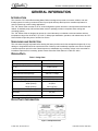
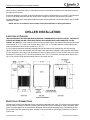
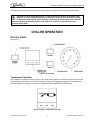
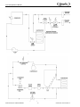
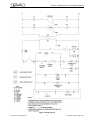
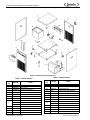
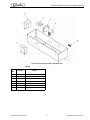
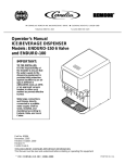
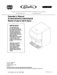
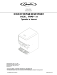
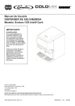
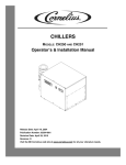
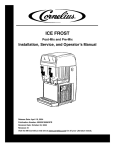
CHILLER
MODELS: CH1001-A
Operator’s & Installation Manual
Release Date: August 9, 2002
Publication Number: 620914301
Revision Date: May 6, 2010
Revision: E
Visit the IMI Cornelius web site at www.cornelius.com for all your Literature needs.
CH SERIES CHILLER
OPERATOR’S & INSTALLATION MANUAL
The products, technical information and instructions contained in this manual are subject
to change without notice. These instructions are not intended to cover all details or variations of the equipment, nor to provide for every possible contingency in the installation,
operation or maintenance of this equipment. This manual assumes that the person(s)
working on the equipment have been trained and are skilled in working with electrical,
plumbing, pneumatic and mechanical equipment. It is assumed that appropriate safety
precautions are taken and that all local safety and construction requirements are being
met, in addition to the information contained in this manual.
To inquire about current revisions of this and other documentation or for assistance with
any Cornelius product contact:
www.cornelius.com
1-800-551-4423
This document contains proprietary information and it may not be
reproduced in any way without permission from Cornelius.
Printed in U.S.A.
Copyright © 2002-2010, All Rights Reserved, IMI Cornelius Inc.
General Information. . . . . . . . . . . . . . . . . . . . . . . . . . . . . . . . . . . . . . . . . . . . . . . . . . . . . . . . . . . . . . . 1
Introduction . . . . . . . . . . . . . . . . . . . . . . . . . . . . . . . . . . . . . . . . . . . . . . . . . . . . . . . . . . . . . . . . . . . 1
Unpacking and Inspection . . . . . . . . . . . . . . . . . . . . . . . . . . . . . . . . . . . . . . . . . . . . . . . . . . . . . . . . 1
Design Data . . . . . . . . . . . . . . . . . . . . . . . . . . . . . . . . . . . . . . . . . . . . . . . . . . . . . . . . . . . . . . . . . . . 1
Data Plate Information . . . . . . . . . . . . . . . . . . . . . . . . . . . . . . . . . . . . . . . . . . . . . . . . . . . . . . . . . . . 1
Chiller Installation . . . . . . . . . . . . . . . . . . . . . . . . . . . . . . . . . . . . . . . . . . . . . . . . . . . . . . . . . . . . . . . . 2
Location of Chiller . . . . . . . . . . . . . . . . . . . . . . . . . . . . . . . . . . . . . . . . . . . . . . . . . . . . . . . . . . . . . . 2
Electrical Connections . . . . . . . . . . . . . . . . . . . . . . . . . . . . . . . . . . . . . . . . . . . . . . . . . . . . . . . . . . . 2
Chiller Operation . . . . . . . . . . . . . . . . . . . . . . . . . . . . . . . . . . . . . . . . . . . . . . . . . . . . . . . . . . . . . . . . . 3
Control Panel . . . . . . . . . . . . . . . . . . . . . . . . . . . . . . . . . . . . . . . . . . . . . . . . . . . . . . . . . . . . . . . . . . 3
Temperature Controller . . . . . . . . . . . . . . . . . . . . . . . . . . . . . . . . . . . . . . . . . . . . . . . . . . . . . . . 3
Control Power Switch/Light . . . . . . . . . . . . . . . . . . . . . . . . . . . . . . . . . . . . . . . . . . . . . . . . . . . . 4
Bypass Light (Blue) . . . . . . . . . . . . . . . . . . . . . . . . . . . . . . . . . . . . . . . . . . . . . . . . . . . . . . . . . . 4
Safety Light (Red) . . . . . . . . . . . . . . . . . . . . . . . . . . . . . . . . . . . . . . . . . . . . . . . . . . . . . . . . . . . 4
High-Pressure Safety . . . . . . . . . . . . . . . . . . . . . . . . . . . . . . . . . . . . . . . . . . . . . . . . . . . . . . . . . 4
Low-Temperature Safety . . . . . . . . . . . . . . . . . . . . . . . . . . . . . . . . . . . . . . . . . . . . . . . . . . . . . . 4
Start Up . . . . . . . . . . . . . . . . . . . . . . . . . . . . . . . . . . . . . . . . . . . . . . . . . . . . . . . . . . . . . . . . . . . . . . 4
Process Water Flow, Units with Pumpt and Tank (Standard) . . . . . . . . . . . . . . . . . . . . . . . . . . 4
Temperature Controller Operation . . . . . . . . . . . . . . . . . . . . . . . . . . . . . . . . . . . . . . . . . . . . . . . . . . . 5
Chiller MAintenance . . . . . . . . . . . . . . . . . . . . . . . . . . . . . . . . . . . . . . . . . . . . . . . . . . . . . . . . . . . . . . 5
Condenser . . . . . . . . . . . . . . . . . . . . . . . . . . . . . . . . . . . . . . . . . . . . . . . . . . . . . . . . . . . . . . . . . 5
Pump Motor . . . . . . . . . . . . . . . . . . . . . . . . . . . . . . . . . . . . . . . . . . . . . . . . . . . . . . . . . . . . . . . . 5
Circulation System . . . . . . . . . . . . . . . . . . . . . . . . . . . . . . . . . . . . . . . . . . . . . . . . . . . . . . . . . . . 5
Filters/Strainers . . . . . . . . . . . . . . . . . . . . . . . . . . . . . . . . . . . . . . . . . . . . . . . . . . . . . . . . . . . . . 5
Fluid Recommendations . . . . . . . . . . . . . . . . . . . . . . . . . . . . . . . . . . . . . . . . . . . . . . . . . . . . . . . . . . . 6
Troubleshooting. . . . . . . . . . . . . . . . . . . . . . . . . . . . . . . . . . . . . . . . . . . . . . . . . . . . . . . . . . . . . . . . . . 6
Warranty . . . . . . . . . . . . . . . . . . . . . . . . . . . . . . . . . . . . . . . . . . . . . . . . . . . . . . . . . . . . . . . . . . . . . . . 12
CH1001-A Chiller Operator’s & Installation Manual
GENERAL INFORMATION
INTRODUCTION
The Cornelius ”CH” Series Recirculating Water Chiller is designed to provide an accurate, reliable, and userfriendly system for cooling a continuous flow of pure liquid and keep that liquid at a constant temperature in
various closed loop or tank cooling applications.
The ”CH” Series Chiller consists of an air–cooled refrigeration system housed in a sturdy sheet metal frame and
cabinet. A standard pump and insulated water reservoir package provides a complete water cooling and
circulating system.
The ”CH” Series Chiller is designed to operate in a clean laboratory or industrial environment where ambient
temperatures range from 40 to100° F (5 to 38° C). With proper installation, operation, and maintenance, the ”CH”
Series Chiller will provide years of trouble free service.
UNPACKING AND INSPECTION
This unit was thoroughly inspected before leaving the factory and the carrier has accepted and signed for it. Any
damage or irregularities should be noted at the time of delivery and immediately reported to the carrier. Request
a written inspection report from the Claims Inspector to substantiate any necessary claims. In the event that an
immediate replacement is necessary, please contact Cornelius Chiller Sales at 1–800–551–4423.
DESIGN DATA
Table 1. Design Data
CH1001-A
Cooling Capacity:
BTU/hr (W) at 80° F (27° C) and 70° F
(21° C)
Compressor Horse Power
Electrical Data:
Voltage/Phase/Hertz/Amperage
Refrigerant Type:
Reservoir Capacity (Gal)
Dimensions:
Depth (inches)
Width (inches)
Height (inches)
Process Connections
Optimum Process Liquid Flow GPM
(Liters/Min)
Condenser Air Flow (CFM)
12,000 (3,515)
1 (.746 kW)
230/1/60, 11 Amps
R134a
6.0 (22.7 liters)
26-1/2 (67cm)
22 (56cm
38-1/4 (97cm)
3/4-inch FPT (S/S)
2.4 (9.0)
712
DATA PLATE INFORMATION
Figure 1. Sample Data Plate
© 2002-2010, IMI Cornelius Inc.
-1-
Publication Number: 620914301
CH1001-A Chiller Operator’s & Installation Manual
When servicing a Cornelius Chiller, it is important to note the information contained on the data plate located in
the upper rear of the Unit.
If technical assistance is needed, the phone technician will need the Serial Number of your chiller. That information
is found on the Data Plate along with the model number, voltage requirement and refrigerant information.
The serial Number is also needed when replacement parts are being ordered or for warranty claims. See CHILLER
WARRANTY PAGE.
NOTE: Be sure to include the serial number on any documentation or billing information.
CHILLER INSTALLATION
LOCATION OF CHILLER
THE CHILLER MUST BE LOCATED NEAR A PROPERLY GROUNDED ELECTRICAL OUTLET. THE CIRCUIT
SHOULD BE FUSED AND NO OTHER ELECTRICAL APPLIANCE SHOULD BE CONNECTED TO THE
CIRCUIT. ALL ELECThe chiller must be located in a well ventilated, indoor area where ambient temperatures will
remain above 40° F (5° C) and never increase above 100° F (38° C). To obtain optimum cooling capacity, the
ambient temperature should be at or below 80° F (27° C).
It is very important that the air intake and discharge sides of the chiller are not obstructed by other free standing
objects. A minimum of two feet of space on all four sides of the chiller will be sufficient to prevent air flow obstructions.
It is also important to direct any hot air discharge from other equipment away from the air intake side of the chiller.
Condenser air entering the “CH” unit should be below 100° F (38° C).Condenser air temperatures above 100° F
(38° C) can cause the high pressure safety control to shut down the unit.
Figure 2. Installation
ELECTRICAL CONNECTIONS
All wiring must conform to the National Electric Code and any applicable local codes. The chiller must be permanently
wired by means of electrical conduit to a properly fused disconnect of proper amperage or wired to a properly rated
power cord and plugged into an outlet with the appropriate disconnect and amperage rating. The electrical junction
box, located on the back panel of the chiller, includes a four terminal strip for power supply connection, as shown in
Figure 2 and
Publication Number: 620914301
-2-
© 2002-2010, IMI Cornelius Inc.
CH1001-A Chiller Operator’s & Installation Manual
The data plate, located next to the junction box, includes the actual voltage, phase, and amerage of the chiller.
CAUTION: On three-phase applications, it is important that the rotation of the pump, when
supplied , is correct. Operating the pump in reverse for more than a few seconds will result
in permanent pump damage. When the pump is operating, the shaft rotation must match the
direction indicated on the pump housing. If the rotation is incorrect, reverse two of the three
incoming power leads.
CHILLER OPERATION
CONTROL PANEL
See Figure 3.
Figure 3. Control Panel
Temperature Controller
The Temperature Controller, shown in Figure 4, uses a PID control algorithm to precisely monitor and control the
process set point temperature. The Unit has a large LED readout that displays temperature. For adjusting set
point and programming options, see section on TEMPERATURE CONTROLLER OPERATION.
Figure 4. CH1001-A Temperature Controller
© 2002-2010, IMI Cornelius Inc.
-3-
Publication Number: 620914301
CH1001-A Chiller Operator’s & Installation Manual
Control Power Switch/Light
A lighted ON/OFF pushbutton switch, shown in Figure 3, is used to switch power to the 24VAC control circuit. The
switch illuminates to indicate that the chiller power is present.
Bypass Light (Blue)
A blue light, shown in Figure 3, is used to indicate when the system is operating at a reduced capacity. The light
cycles on and off in response to the temperature controller when the system temporarily requires less cooling.
Safety Light (Red)
A red light, shown in Figure 3, is used to indicate that a fault has occurred in the chiller operation. The following
conditions illuminate the safety light.
A. High refrigerant pressure.
B. Low process water temperature.
C. Low process water flow (optional, see Optional Equipment section)
High-Pressure Safety
The high-pressure safety, shown in Figure 3, shuts down the compressor and pump when the refrigerant head
pressure reaches 240-PSIG for R-134A refrigerant units. The high pressure switch must be reset manually. The
switch is located in the electrical box which must be accessed by removing the chiller lid. The high-pressure
switch can be re-set by depressing the reset button through the opening in the electrical box cover. If the control
opens again, check the setting with a set of refrigeration gauges. If the setting is correct, contact the Cornelius
Technical Service Department.
Low-Temperature Safety
The low-temperature safety shuts down the compressor and the pump when the process water temperature
drops below 35° F (1.7° C). The switch automatically resets when the water temperature is restored to 38° F (3.3°
C). The low temperature control is located in the electrical box.
START UP
WARNING: Never operate the chiller with it’s panels removed.
Always use the power switch to turn off the chiller when it is not being used (see Fluid
Recommendations page).
Always ensure that all air inlets and outlets are free from obstruction.
Be sure that the reservoir is filled with fluid prior to powering up the unit.
Process Water Flow, Units with Pumpt and Tank (Standard)
Follow standard plumbing practices and local codes in making water connections. The chiller inlet and outlet
connections are 3/4”. Flexible hose and fittings are recommended for plumbing the system. A No. 20 mesh
strainer should be installed on the chiller inlet to prevent foreign particles from entering the system and should be
cleaned monthly. Lines should be routed with as few bends as possible. Prevent lines from running near
radiators, hot water pipes, etc. Any lengths of tubing that are exposed to high ambient temperatures should be
insulated to prevent condensation and/or significant liquid heat loss.
After ensuring that the system is free from the obstruction, that all valves are open, and the reservoir when
available is full, push the Control Power switch to the “ON” position. The pump should now be operating.
All chillers with pumps and tank are supplied with a pressure regulating valve on the pump discharge. This valve
is preset at the factory to ensure that system pressure does not exceed the capabilities of the pump motor and/or
piping. If this valve requires adjustment, please contact the Cornelius Service Group for the proper setting
procedure and pressures.
Publication Number: 620914301
-4-
© 2002-2010, IMI Cornelius Inc.
CH1001-A Chiller Operator’s & Installation Manual
Process water flow can be adjusted via a throttling valve and flow meter installed in the chiller outlet line.
Once the flow has been established, the thermostat can be programmed to the desired set-point.
TEMPERATURE CONTROLLER OPERATION
During normal operation, the process temperature is displayed on the Controller, as shown in Figure 4. Follow the
procedure below to adjust the Controller set point:
1.
Push and hold the “ *” button located at the bottom left corner of the controller. The set point is
displayed.
2.
While holding the “ *” button, press
(“ UP” ) or
point until the desired value is displayed.
3.
Release the “ *” button. The display again shows the system liquid temperature. The set point can
be viewed at any time by pressing the “ *” button.
(“ DOWN”) button to raise or lower the set
The controller set point range has been preset at the factory. The range is 40° F (5° C) to 100° F (38° C). If
operation outside this range is required, contact the Cornelius Technical Services Department.
CHILLER MAINTENANCE
WARNING: Disconnect electrical power to the chiller to prevent personal injury before
attempting any internal maintenance. Only qualified personnel should service the internal
components or electrical wiring.
Condenser
On air-cooled chillers, the condenser fins should be cleaned by blowing compressed air through the condenser
from the fan side. Dirt and debris accumulate on the condenser fins over time and this build up can severely
reduce the performance of the chiller. Cleaning of the condenser coil fins should be done approximately every
three months, depending upon cleanliness of the operating environment.
Pump Motor
The pump motor should be lubricated with thirty drops of SAE 10 oil once a year.
Circulation System
The circulation system should be drained and flushed periodically to avoid build up and a possible flow restriction
caused by contaminants.
Filters/Strainers
The “Y” strainer, located inside the unit at the inlet of the pump, should be cleaned periodically depending on the
operating environment. If a reduction in flow or cavitation of the pump occurs, remove the strainer, flush it out with
water and replace it.
© 2002-2010, IMI Cornelius Inc.
-5-
Publication Number: 620914301
CH1001-A Chiller Operator’s & Installation Manual
FLUID RECOMMENDATIONS
Cornelius chillers are designed to operate with water to provide maximum performance for temperatures of 40° F
(4.4° C) to 100° F (37.8° C).
Distilled Water
De-Ionized Water
(1-5 Meg ohms)
Acceptable
De-Ionized Water
(5+ Meg ohms)
Acceptable with Stainless Steel & PVC only (No Copper
or Brass)
Propylene Glycol
(Lab & Industrial Grade)
Acceptable - 30% Glycol/70% Water
(For Applications with Temperatures below 40° F)
Acceptable - 30% Glycol/70% Water
(For Applications with Temperatures below 40° F)
NOT Acceptable
Acceptable
Lab & Industrial Grade Ethylene Glycol
Mineral/Hydraulic Oils
(Commercial/Automotive Antifreeze)
(Silicate Rust Inhibitors in Automotive/Commercial antifreeze damages pump seals and housing which lead to
failure.)
Acidic/Basic Solutions
(Above 8 or below 6 PH)
Mineral/Hydraulic Oils
(Viscosity > 50 Centistrokes)
Not Acceptable
Not Acceptable
For questions regarding special or other fluids contact IMI Cornelius at 1-800-551-4423.
To purchase Lab or Industrial Glycol contact:
IMI Cornelius, 1-800-551-4423 - Part No. 111521000, 5 Gal.
TROUBLESHOOTING
WARNING: Disconnect electrical power to the chiller to prevent personal injury before
attempting any internal maintenance. Only qualified personnel should service the internal
components or electrical wiring.
If repairs to the chiller must be made, disconnect electrical power to the unit, then shut off
the water source.
Trouble
Problem Cause
A. No Power to unit
Remedy
A. Check main disconnect fuses,
wiring and power lead to unit.
B. Defective Control Power Switch B. Replace Switch
Chiller does not operate, Power
Light “OFF”.
C. Defective Control Transformer
C. Replace Transformer
D. Wrong voltage supplied to unit.
D. Supplied voltage must be within
±10% of nameplate rating.
E. Blown fuse.
E.
F.
Publication Number: 620914301
-6-
Replace fuse (1 Amp).
© 2002-2010, IMI Cornelius Inc.
CH1001-A Chiller Operator’s & Installation Manual
Trouble
Pump does not operate, but Power
Light is “ON”.
Problem Cause
Remedy
A. Line to or from chiller is
restricted.
A. Inspect lines and remove any
obstructions.
B. Internal or external filter is
blocked with debris.
B. Remove and clean strainer,
then replace.
C. Pump contactor is defective.
C. Replace contactor.
D. Damaged pump motor or impel- D. Replace pump motor or impeller.
ler.
Unit runs continuously, but is not
cooling process water enough.
Chiller does not operate, but power
light is “ON” and red safety light is
“ON”.
A. Condenser is restricted.
A. Clean condenser.
B. Unit low on refrigerant.
B. Call service
C. Inefficient compressor.
C. Call service.
D. Unit is undersized for application.
D. Call Cornelius chiller sales rep.
E. Bypass gas valve stuck open.
E. Replace solenoid valve.
A. Unit is operating under high
pressure conditions.
A. Check for dirty condenser fins
or obstruction of chiller air
intake. Press high pressure
manual reset switch. If this
problem persist, contact Cornelius Service Department.
B. Unit is operating under low tem- B. Low or now process water flow.
Ensure that there is adequate flow
perature conditions.
through the system plumbing.
OR
Process water is too cold, below
35° F. Increase thermostat setting or bypass valve stuck open.
Replace solenoid valve. Check
for proper voltage.
OR
Defective thermostat, replace.
C. Unit has experienced low flow
condition.
C. Check for obstruction in process
water line plumbing.
NOTE: When servicing a Cornelius chiller, it is important to note all information provided on the
DATA PLATE located on the upper rear of the unit. If technical assistance is needed, the Cornelius
Service Technician will need this information along with any description of the problem(s) you are
encountering. The serial no. and other information will also be required when ordering replacement
parts and any other Warranty Claims.
© 2002-2010, IMI Cornelius Inc.
-7-
Publication Number: 620914301
Ice Frost Operator’s Manual
Figure 5. Process Water Flow Schematic
Figure 6. Refrigeration Schematic
Publication Number: M620919596OPR
-8-
© 2004-2007, IMI Cornelius Inc.
CH1001-A Chiller Operator’s & Installation Manual
Figure 7. Wiring Diagram
© 2002-2010, IMI Cornelius Inc.
-9-
Publication Number: 620914301
CH1001-A Chiller Operator’s & Installation Manual
Figure 8. Cabinet Section Exploded View
Table 1. Cabinet Section
Table 1. Cabinet Section
Item
No.
Part No.
1
2
3
4
620028005
620028001
620043210
620604501
Base, Pump/Tank
Panel, Front
Electrical Junction Box
Condensing Unit
5
6
7
620028003
620028004
620604302
Panel, Side
Lid, Chiller
Accumulator
32357
187483000
32382
620306708
41331
61003
60686
Pump
Clamp
Motor
Electrical Box Assy
Y-Strainer
TXV
Filter Dryer
8
10
11
12
13
Item
No.
Name
Publication Number: 620914301
14
15
16
17
18
19
20
21
22
23
24
25
26
- 10 -
Part No.
60687
620602503
620603201
22870
620313205
620602701
620701209
620028002
620602703
620602704
40646
620315101
620315102
620028007
Name
Sight Glass
Evaporator Assy
Foamed Reservoir
Fill Port (3/4-in. SS Coupling)
Switch, Power
Controller, Temperature
Gauge, Pressure
Panel, Rear
Solenoid Valve, Hot Gas
Solenoid Coil, Hot Gas
Bypass Valve, Water
Indicator, Red
Indicator, Blue
Base, Refrigeration
© 2002-2010, IMI Cornelius Inc.
CH1001-A Chiller Operator’s & Installation Manual
Figure 9. Electrical Box Assemby, Exploded View
Table 2
Item
No.
Part No.
Name
1
620028012
Enclosure, Electric Box
2
32829R
Transformer
3
31001
Safety, Low Temp
4
60501
Safety, High Pressure
5
33082
Pump/Relay
8
620305902
Compressor/Contactor
10
31407
Fuse Block
© 2002-2010, IMI Cornelius Inc.
- 11 -
Publication Number: 620914301
CH1001-A Chiller Operator’s & Installation Manual
WARRANTY
IMI Cornelius Inc. warrants that all equipment and parts are free from defects in material and workmanship under
normal use and service. For a copy of the warranty applicable to your Cornelius or Wilshire product, in your
country, please write, fax or telephone the IMI Cornelius office nearest you. Please provide the equipment model
number, serial number and the date of purchase.
Publication Number: 620914301
- 12 -
© 2002-2010, IMI Cornelius Inc.
IMI Cornelius Inc.
www.cornelius.com